Table of Contents
Advertisement
Quick Links
Advertisement
Table of Contents

Related Manuals for AXIOMTEK eBOX570 Series


Summary of Contents for AXIOMTEK eBOX570 Series
- Page 1 Series Embedded System User’s Manual...
-
Page 2: Disclaimers
Axiomtek does not make any commitment to update any information in this manual. Axiomtek reserves the right to change or revise this document and/or product at any time without notice. No part of this document may be reproduced, stored in a retrieval system, or transmitted in any forms or by any means, electronic, mechanical, photocopying, recording, among others, without prior written permissions of Axiomtek Co., Ltd. -
Page 3: Safety Precautions
Safety Precautions Before getting started, please read the following important safety precautions. The eBOX570 does not come with an operating system which must be loaded first before installation of any software into the computer. Be sure to ground yourself to prevent static charge when installing any internal components. -
Page 4: Classifications
Classifications Degree of production against electric shock: not classified Degree of protection against ingress of water: IP40 Equipment not suitable for use in the presence of a flammable anesthetic mixture with air, oxygen or nitrous oxide. Mode of operation: Continuous... -
Page 5: General Cleaning Tips
General Cleaning Tips Please keep the following precautions in mind while understanding the details fully before and during any cleaning of the computer and any components within. A piece of dry cloth is ideal to clean the device. Be cautious of any tiny removable components when using a vacuum cleaner to absorb dirt on the floor. -
Page 6: Scrap Computer Recycling
Scrap Computer Recycling Please inform the nearest Axiomtek distributor as soon as possible for suitable solutions in case computers require maintenance or repair; or for recycling in case computers are out of order. Trademarks Acknowledgments Axiomtek is a trademark of Axiomtek Co., Ltd. -
Page 7: Table Of Contents
Table of Contents Disclaimers ......................ii Safety Precautions ....................iii Classifications ....................... iv General Cleaning Tips ................... v Scrap Computer Recycling ................... vi SECTION 1 INTRODUCTION................. 1 General Descriptions ................. 1 System Specifications ............... 3 1.2.1 CPU ........................3 1.2.2 I/O System ...................... - Page 8 Advanced Menu ................37 Chipset Menu ................... 48 Boot Menu ..................52 Save & Exit Menu ................53 viii...
-
Page 9: Section 1 Introduction
Series user’s Manual SECTION 1 INTRODUCTION This section contains general information and detailed specifications of the eBOX570. Section 1 consist of the following sub-sections: ◼ General Descriptions ◼ System Specifications ◼ Dimensions ◼ I/O Outlets ◼ Packing List ◼... - Page 10 Series user’s Manual Features ⚫ 13th gen Intel® Core™ processor (Raptor Lake P) ⚫ Fanless design with operating temperature from -40°C to 70°C ⚫ 1 DDR4 SO-DIMM for up to 32GB of memory ⚫ Supports the USB power on/off control function ⚫...
-
Page 11: System Specifications
Series user’s Manual 1.2 System Specifications 1.2.1 CPU ⚫ CPU (13th gen) ® ◼ Intel Core™ i7-1365UE(1.70 GHz, 15W) ® ◼ Intel Core™ i5-1335UE (1.3 GHz, 15W) ◼ ® ® Intel Celeron U300E (1.1 GHz, 15W) ⚫ Chipset ◼... -
Page 12: System Specifications
Series user’s Manual ⚫ Switch ◼ 1 x ATX PWR switch ◼ 1 x Remote PWR switch ◼ 1 x Reset switch ⚫ Antenna & SIM ◼ 2 x SMA type openings for antenna ◼ 1 x internal SIM slot ⚫... -
Page 13: Driver Cd Contents
2.5 kg (5.5 lb) with package ⚫ Dimension ◼ 120 mm (4.72") x 178 mm (7.01") x 65 mm (2.56") 1.2.4 Driver CD Contents Please download the following eBOX570 drivers from the Axiomtek official website. ⚫ Ethernet ⚫ Chipset ⚫... -
Page 14: Dimensions
Series user’s Manual 1.3 Dimensions The following diagrams show dimensions and outlines of the eBOX570. 1.3.1 System Dimensions Introduction... -
Page 15: Wall-Mount Bracket Dimensions
Series user’s Manual 1.3.2 Wall-mount Bracket Dimensions Users can get 4pcs truss head M3*6L screws for fixing the wall mount kit from the accessories box. Note: When users install wall mount kit, please turn the LAN ports side outlet towards the floor. - Page 16 Series user’s Manual Wall-mount Bracket Assembly Drawing Users can get 4pcs truss head M3*6L screws for fixing the wall mount kit from the accessories box. Note : If users install the screws in drywall, use the hollow wall anchors to ensure that unit does not pull away from the wall due to prolonged strain between the cable and power connector.
-
Page 17: Din-Rail Bracket Dimensions
Series user’s Manual 1.3.3 Din-Rail Bracket Dimensions Users can get 8pcs truss head M3*6L screws for fixing the wall mount kit from the accessory box. Introduction... - Page 18 Series user’s Manual Din-Rail Bracket Assembly Drawing Users can get 8pcs truss head M3*6L screws for fixing the Din Rail kit from the accessory box. Introduction...
-
Page 19: Vesa Mount Bracket Dimensions
Series user’s Manual 1.3.4 VESA Mount Bracket Dimensions Users can get 4pcs truss head M3*6L screws for fixing the VESA mount kit from the accessory box. Introduction... - Page 20 Series user’s Manual VESA Mount Bracket Assembly Drawing Users can get 4pcs truss head M3*6L screws for fixing the Din Rail kit from the accessory box. Introduction...
-
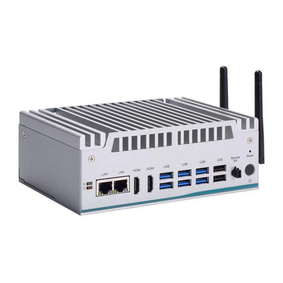
Page 21: I/O Outlets
Series user’s Manual 1.4 I/O Outlets The following figures show I/O outlets on the eBOX570. Front View Rear View Side View Introduction... -
Page 22: Packing List
1335UE, 2 HDMI, 2 LANs, 8 USB, 2 COM, and 12 VDC ® ® Fanless embedded system with Intel Celeron U300E, eBOX570-13P-Cel 2 HDMI, 2 LANs, 8 USB, 2 COM, and 12 VDC Please contact Axiomtek’s distributors immediately in case any abovementioned items are missing. Introduction... -
Page 23: Section 2 Hardware Installation
Series user’s Manual SECTION 2 HARDWARE INSTALLATION The eBOX570 is convenient for various hardware configurations, such as DRAM, NVMe, PCI Express Mini card modules. Section 2 contains guidelines for hardware installation. 2.1 Installation of DRAM Module Step 1 Turn off the system and unplug the power cord. -
Page 24: Installation Of Mini Pcie Module (Cn11)
Series user’s Manual 2.2 Installation of Mini PCIe Module (CN11) The eBOX570 provides one full-size mini-PCIe socket with SIM card support. Customers can use this socket for install wireless modules . Install WiFi Mini PCIe Module, please follow the instructions as blow: Step 1 Turn off the system and unplug the power cord. - Page 25 Series user’s Manual Install LTE Mini PCIe Module, please follow the instructions as blow: Step 1 Turn off the system and unplug the power cord. Step 2 Loosen five screws to remove bottom cover and locate PCIe mini card slot within the red line as marked.
- Page 26 Series user’s Manual Step 4 Insert the LTE mPCIe module on a 45-degree angle into the mPCIe slot and secure the module with M3x2 screw. Step 5 Remove the antenna cover from system, fix the SMA connector of the IPEX-to-SMA cable to one of the two antenna apertures on the side panel.
-
Page 27: Installation Of M.2 Key E Mini Pcie Module (Cn3)
Series user’s Manual 2.3 Installation of M.2 Key E Mini PCIe Module (CN3) The eBOX570 equipped with an M.2 Key E 2230 socket for users to install an Wi-Fi 6E wireless module. Step 1 Turn off the system and unplug the power cord. - Page 28 Series user’s Manual Step 5 Remove the antenna cover from system, fix the SMA connector of the IPEX-to-SMA cable to one of the two antenna apertures on the side of panel. Step 6 Put the bottom cover and fasten all screws back onto the system.
-
Page 29: Installation Of Nvme Ssd Module (Cn10)
Series user’s Manual 2.4 Installation of NVMe SSD Module (CN10) The eBOX570 equipped with an M.2 Key M 2280 socket (PCIex4 signal) for users to install an NVMe SSD module. Please refer to the following instructions and illustrations for the installation of the NVMe SSD module. - Page 30 Series user’s Manual This page is intentionally left blank. Hardware Installation...
-
Page 31: Section 3 Jumper & Connector Settings
Series user’s Manual SECTION 3 JUMPER & CONNECTOR SETTINGS Proper jumper settings configure the eBOX570 to meet various application needs. Hereby all jumpers settings along with their default settings are listed for devices onboard. 3.1 Locations of Jumpers & Connectors PSB524 Top View Jumper &... - Page 32 Series user’s Manual PSB524 Bottom View 【Note】: It is strongly recommended that any unmentioned jumper settings should not be modified without instructions by Axiomtek FAEs. Any modifications without instructions might cause system failure. Jumper & Connector Settings...
-
Page 33: Clear Cmos Setting
Series user’s Manual 3.2 Clear CMOS Setting please see the following setting for clear CMOS. 3.2.1 Clear CMOS (SW1) Use the switch SW1 to for clear CMOS. Jumper & Connector Settings... -
Page 34: Connectors
Series user’s Manual 3.3 Connectors Please refer to below connector table to get their pin assignments. External Connectors Sections DC-in Phoenix Power Connector (CN1) 3.3.1 HDMI Connector (CN12, CN13) 3.3.2 Serial Port Connector (CN4, CN5) 3.3.3 USB 3.2 Connector (CN15, CN16, CN17) 3.3.4... -
Page 35: Dc-In Phoenix Power Connector (Cn1)
Series user’s Manual 3.3.1 DC-in Phoenix Power Connector (CN1) The system supports 9~36V Phoenix DC-in connector for system power input. Pins Signals 3.3.2 HDMI Connector (CN12, CN13) The HDMI (High-Definition Multimedia Interface) is a compact digital interface which is capable of transmitting high-definition video and high-resolution audio over a single cable. -
Page 36: Serial Port Connector (Cn4,Cn5)
Series user’s Manual 3.3.3 Serial Port Connector (CN4,CN5) The system has two serial ports. COM1~COM2 are RS-232/422/485 ports. Please refer to Chapter 4 for the detail of BIOS setting. *Baud rate support up to 115200* Pins RS-232 RS-422 RS-485... -
Page 37: Usb 3.2 Connector (Cn15, Cn16, Cn17) / Usb 2.0 Connector (Cn18)
Series user’s Manual 3.3.4 USB 3.2 Connector (CN15, CN16, CN17) / USB 2.0 Connector (CN18) The system has four USB 3.2 gen2 (10GB/s), two USB 3.2 gen1 (5GB/s), two USB 2.0 ports which are ideal for connecting USB devices, such as scanner, camera, and USB devices, etc. -
Page 38: Ethernet Connector (Lan1~Lan2)
Series user’s Manual 3.3.5 Ethernet Connector (LAN1~LAN2) The board has two RJ-45 Gbe ports connectors, one LAN port is designed by Intel i219-LM and three LAN ports are Intel i210-IT. Pins LAN Signal Pins LAN Signal MDI0+ MDI2+ MDI0-... -
Page 39: Remote Power Switch
Series user’s Manual 3.3.8 Remote Power Switch One 2-pin connector output for remote power on/off switch. Functions Descriptions Short(1-2) Turn on/off system Open Keep system status 3.3.9 SIM Card Slots (CN9) The eBOX570 includes one SIM slot: CN9 on top side that support mini PCIe slot (for CN11), It is mainly used in wireless network application on CN11. -
Page 40: 2230 Key E Slot (Cn3)
Series user’s Manual No use No use W_DISABLE# PERST# PE_RXN3/ +3.3VSB SATA_RXP PE_RXP3/ SATA_RXN +1.5V SMB_CLK PE_TXN3/ SMB_DATA SATA_TXN PE_TXP3/ SATA_TXP USB_D8- USB_D8+ +3.3VSB +3.3VSB No use No use No use No use No use +1.5V No use No use +3.3VSB... - Page 41 Series user’s Manual CNVI_RGI_DT CNVI_RGI_RSP PCIE_TX_+ CNVI_BRI_DT PCIE_TX_- CL_RST CL_DATA PCIE_RX_+ CL_CLK PCIE_RX_- CNVI_GNSS_PA_BLANKING CNVI_MFUART_TXD CLK_PCIE_+ CNVI_MFUART_RXD CLK_PCIE_- SUSCLK (+3.3V Level) PERST# (+3.3V Level) CLKREQ0# BT_RF_KILL PEWAKE0# WIFI_RF_KILL CNVI_WT_DATA1_D- CNVI_WT_DATA1_D+ CNVI_WT_DATA0_D- CNVI_WT_DATA0_D+ CNVI_WT_CLK_D- +3.3V_SBY CNVI_WT_CLK_D+ +3.3V_SBY Jumper & Connector Settings...
-
Page 42: 2280 Key M Slot (Cn10)
Series user’s Manual 3.3.12 M.2 2280 Key M slot (CN10) The M.2 2280 Key M for NVMe/SATA Module by BIOS select (default SATA). Pins Signals Pins Signals +3.3V +3.3V PCIEx4_B_RX_DN3 PCIEx4_B_RX_DP3 KEY_M_LED_N PCIEx4_B_TX_DN3 +3.3V +3.3V PCIEx4_B_TX_DP3 +3.3V PCIEx4_B_RX_DN2 +3.3V... -
Page 43: Section 4 Bios Setup Utility
Series user’s Manual SECTION 4 BIOS SETUP UTILITY This section provides users with detailed descriptions in terms of how to set up basic system configurations through the BIOS setup utility. 4.1 Starting To enter the setup screens, follow the steps below: Turn on the computer and press the <Del>... -
Page 44: Main Menu
Series user’s Manual 4.3 Main Menu The Main Menu screen is the first screen users see when entering the setup utility. Users can always return to the Main setup screen by selecting the Main tab. System Time/Date can be set up as described below. -
Page 45: Advanced Menu
Series user’s Manual 4.4 Advanced Menu The Advanced menu also allows users to set configuration of the CPU and other system devices. Users can select any items in the left frame of the screen to go to sub menus: ►... - Page 46 Series user’s Manual ACPI Settings Use this screen to select options for the ACPI configuration and change the value of the selected option. A description of the selected item appears on the right side of the screen. ACPI Sleep State When the sleep button is pressed, the system will be in the ACPI sleep state.
- Page 47 Series user’s Manual Trust Computing If users install a security device, such as TPM, users will see the following information for the TPM device and status. BIOS Setup Utility...
- Page 48 Series user’s Manual CPU Configuration This screen shows the CPU version and its detailed information. Turbo Mode This item is for enabling or disabling turbo mode. When enabled, it allows processor cores to run faster than marked frequency under certain conditions. The default is Enabled Mode.
- Page 49 Series user’s Manual Storage Configuration Users can read the current installed hardware configurations from those SATA ports in the SATA Configuration menu. During system boot up, BIOS will detect the present SATA devices automatically. BIOS Setup Utility...
- Page 50 Series user’s Manual NVMe Configuration This screen shows NVMe device information. BIOS Setup Utility...
- Page 51 Series user’s Manual AMT Configurations Users can use this screen to configure AMT parameters. ® Intel Enable or disable Intel Active Management Technology BIOS Extension. ® The default is Disabled. BIOS Setup Utility...
- Page 52 Series user’s Manual F81804 Super IO Configurations Use this screen to select options for the F81966 Super IO Configurations and change the value of the selected option. A description of the selected item appears on the right side of the screen.
- Page 53 Series user’s Manual Serial Port 1 Serial Port 2 BIOS Setup Utility...
- Page 54 Series user’s Manual Hardware Monitor This screen monitors hardware health status. This screen displays the temperature of system and CPU as well as system voltages (VCC_RTC, +3V STBY, +5V STBY, +3V and +5V). BIOS Setup Utility...
- Page 55 Series user’s Manual USB Configurations This screen shows USB configuration. BIOS Setup Utility...
-
Page 56: Chipset Menu
Series user’s Manual 4.5 Chipset Menu The Chipset menu allows users to change the advanced chipset settings. Users can select any of the items in the left frame of the screen to go to the sub menus: ► PCH-IO Configurations For items marked with “”, please press <Enter>... - Page 57 Series user’s Manual PCH-IO Configurations This screen allows users to set PCH parameters. Wake on LAN Enable Enable or disable integrated LAN to wake the system. BIOS Setup Utility...
- Page 58 Series user’s Manual Security Menu Administrator Password This item indicates whether an administrator password has been set (installed or uninstalled). User Password This item indicates whether a user password has been set (installed or uninstalled). BIOS Setup Utility...
- Page 59 Series user’s Manual Secure Boot Mode Use this item to set UEFI Secure Boot Mode to Standard mode or Custommode. This change is effective after save. After reset, this mode will return to Standardmode. Restore Factory Keys Use this item to force System to User Mode, to install factory default SecureBoot key databases.
-
Page 60: Boot Menu
Series user’s Manual 4.6 Boot Menu The Boot menu allows users to change boot options of the system. Setup Prompt Timeout Use this item to set up number of seconds to wait for setup activation key where 65535(0xFFFF) means indefinite waiting. -
Page 61: Save & Exit Menu
Series user’s Manual 4.7 Save & Exit Menu The Save & Exit menu allows users to load system configurations with optimal or fail-safe default values. Save Changes and Exit When users have completed the system configuration changes, select this option to leave Setup and return to Main Menu. - Page 62 Series user’s Manual Save Changes Having completed the system configuration changes, select this option to save changes. Select Save Changes from the Save & Exit menu and press <Enter>. Select Yes to save changes. Discard Changes Select this option to quit Setup without making any permanent changes to the system configurations.
Need help?
Do you have a question about the eBOX570 Series and is the answer not in the manual?
Questions and answers