
Related Manuals for AXIOMTEK SHB130 Series


Summary of Contents for AXIOMTEK SHB130 Series
- Page 1 SHB130 Series ® Intel Socket 1150 Core i7 / Core i5 / Core i3 Processor ® PICMG v1.3 Full-size CPU Card User’s Manual...
-
Page 2: Disclaimers
Axiomtek does not make any commitment to update the information in this manual. Axiomtek reserves the right to change or revise this document and/or product at any time without notice. No part of this document may be reproduced, stored in a retrieval system, or transmitted, in any form or by any means, electronic, mechanical, photocopying, recording, or otherwise, without the prior written permission of Axiomtek Co., Ltd. -
Page 3: Esd Precautions
Wear a wrist-grounding strap, available from most electronic component stores, when handling boards and components. Trademarks Acknowledgments Axiomtek is a trademark of Axiomtek Co., Ltd. ® Windows is a trademark of Microsoft Corporation. AMI is a trademark of American Megatrend Inc. -
Page 4: Table Of Contents
Table of Contents Disclaimers ..................... ii ESD Precautions ................... iii Chapter 1 Introduction ..........1 Features ....................1 Specifications ..................2 Utilities Supported ................3 Chapter 2 Board and Pin Assignments ....5 Board Dimensions and Fixing Holes ..........5 Board Layout .................. - Page 5 Installing the Memory ............... 24 Chapter 4 Hardware Description ......25 Microprocessors ................25 BIOS ....................25 System Memory ................. 25 I/O Port Address Map ................ 26 Interrupt Controller (IRQ) Map ............28 Memory Map ..................31 Chapter 5 AMI BIOS Setup Utility ......33 Starting ....................
- Page 6 iAMT Web Console ..................72 Appendix F PICMG v1.3 Interface Definition ..75 ®...
-
Page 7: Chapter 1 Introduction
SHB130 LGA1150 Full-size CPU Card Chapter 1 Introduction ® The SHB130 PICMG v1.3 full-size Single Board Computer supports LGA1150 socket for ® Intel Core i7 desktop processor, i5 desktop processor, i3 desktop processor with 22nm ® technology and transfer rate 1333/1600MHz. The board integrates Intel Q87 chipset that delivers outstanding system performance through high-bandwidth interfaces, multiple I/O functions for interactive applications and various embedded computing solutions. -
Page 8: Specifications
SHB130 LGA1150 Full-size CPU Card Specifications ® Intel Core i7 desktop processor. ® Intel Core i5 desktop processor. ® Intel Core i3 desktop processor. CPU TDP up to 65W System Chipset ® Intel Q87. -
Page 9: Utilities Supported
SHB130 LGA1150 Full-size CPU Card Resolution: Analog output - the analog port utilizes an integrated 400MHz 24-bit RAMDAC that can directly drive a standard progressive scan analog monitor up to a resolution of 2048x1536 pixels with 32-bit color at 75Hz. ... - Page 10 SHB130 LGA1150 Full-size CPU Card This page is intentionally left blank. Introduction...
-
Page 11: Board And Pin Assignments
SHB130 LGA1150 Full-size CPU Card Chapter 2 Board and Pin Assignments Board Dimensions and Fixing Holes Board and Pin Assignments... -
Page 12: Board Layout
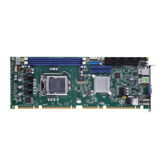
SHB130 LGA1150 Full-size CPU Card Board Layout Board and Pin Assignments... -
Page 13: Jumper Settings
And remove jumper clip from 2 jumper pins to open. The following illustration shows how to set up jumper. Before applying power to SHB130 Series, please make sure all of the jumpers are in factory default position. Below you can find a summary table and onboard default settings. -
Page 14: Audio Amplifier Selection (Jp1)
SHB130 LGA1150 Full-size CPU Card 2.3.1 Audio Amplifier Selection (JP1) This jumper is for enabling or disabling audio amplifier. Function Setting Disable (Default) 1-3, 2-4 close Enable 3-5, 4-6 close 2.3.2 Restore BIOS Optimal Defaults (JP2) Put jumper clip to pin 2-3 for a few seconds then move it back to pin 1-2. Doing this procedure can restore BIOS optimal defaults. -
Page 15: Connectors
SHB130 LGA1150 Full-size CPU Card Connectors Signals go to other parts of the system through connectors. Loose or improper connection might cause problems, please make sure all connectors are properly and firmly connected. Here is a summary table which shows all connectors on the hardware. Connector Description External Temperature Sensor Connector (Optional) -
Page 16: External Temperature Sensor Connector (Cn1) (Optional)
SHB130 LGA1150 Full-size CPU Card 2.4.1 External Temperature Sensor Connector (CN1) (Optional) This is a 2-pin connector for external temperature sensor (NTC thermistor) interface. The thermistor value should be 10K and its B value is 3435K. Signal Sensor Input 2.4.2 SMBus Connector (CN2) The SMBus interface is available through this connector. -
Page 17: Internal Usb 3.0 Connector (Cn4)
SHB130 LGA1150 Full-size CPU Card 2.4.4 Internal USB 3.0 Connector (CN4) The CN4 is an internal connector for USB 3.0 interface. Signal Signal VBUS0 SSRX0- VBUS1 SSRX0+ SSRX1- SSRX1+ SSTX0- SSTX0+ SSTX1- SSTX1+ USB0- USB0+ USB1- USB1+ 2.4.5 LAN External LED Connectors (CN5 and CN6) The LAN2 and LAN1 external LED interfaces are available through CN5 and CN6, respectively. -
Page 18: Internal Usb 2.0 Connectors (Cn8, Cn11 And Cn12)
SHB130 LGA1150 Full-size CPU Card 2.4.7 Internal USB 2.0 Connectors (CN8, CN11 and CN12) These are internal connectors for USB 2.0 interfaces. CN8(USB port 6 and 7), Signal Signal CN11(USB port 8 and 9), USB_PWR USB_PWR CN12(USB port 2 and 3) USB - USB - USB +... -
Page 19: Displayport Connector (Cn10) (Optional)
SHB130 LGA1150 Full-size CPU Card 2.4.9 DisplayPort Connector (CN10) (Optional) DisplayPort (digital display interface standard) is available through connector CN10. Note that connector CN10 is co-layout with VGA port (CN9). Signal LANE0 LANE0# LANE1 LANE1# LANE2 LANE2# LANE3 LANE3# HDMI_DET AUX CH AUX CH# Hot Plug Detect... -
Page 20: Front Panel Connector (Cn13)
SHB130 LGA1150 Full-size CPU Card 2.4.10 Front Panel Connector (CN13) Signal PWRLED+ EXT SPK- Buzzer PWRLED- N.C. N.C. EXT SPK+ PWRSW- PWRSW+ HW RST- HW RST+ HDDLED- HDDLED+ Power LED Pin 1 connects anode(+) of LED and pin 5 connects cathode(-) of LED. The power LED lights up when the system is powered on. -
Page 21: External Usb 3.0 Connectors (Cn14 And Cn17)
SHB130 LGA1150 Full-size CPU Card 2.4.11 External USB 3.0 Connectors (CN14 and CN17) These are standard USB 3.0 connectors on rear I/O for installing USB 3.0 compliant interface peripherals. Signal CN14 (USB 3.0 port 4), CN17 (USB 3.0 port 3) StdA_SSRX- StdA_SSRX+ GND_DRAIN... -
Page 22: Fan Connectors (Fan1, Fan2 And Fan3)
SHB130 LGA1150 Full-size CPU Card 2.4.13 FAN Connectors (FAN1, FAN2 and FAN3) Fans are always needed for cooling down CPU and system temperature. The board has three fan connectors. You can find fan speed option(s) at BIOS Setup Utility if either fan is installed. -
Page 23: Parallel Port (Print1)
SHB130 LGA1150 Full-size CPU Card 2.4.15 Parallel Port (PRINT1) This board has a multi-mode parallel port supporting: Standard Mode: IBM PC/XT, PC/AT and PS/2 are compatible with bi-directional parallel port. Enhanced Mode: Enhance parallel port (EPP) is compatible with EPP 1.7 and EPP 1.9 (IEEE 1284 compliant). -
Page 24: Com Connectors (Com1~Com5)
SHB130 LGA1150 Full-size CPU Card 2.4.17 COM Connectors (COM1~COM5) The COM1 port supports RS-232/RS-422/RS-485 mode operation, see table below for its pin assignments. You can change the transmission mode via BIOS setting. RS-232 RS-422 RS-485 Data Carrier DATA- Detect (DCD) Data Set Ready No connector No connector... -
Page 25: Audio Connector (Audio1)
SHB130 LGA1150 Full-size CPU Card 2.4.18 Audio Connector (AUDIO1) The AUDIO1 is an internal audio connector. Signal Signal MIC IN LINE_IN_L LINE_IN_R LINE_OUT_L LINE_OUT_R 2.4.19 Power Connector (ATX2) Steady and sufficient power can be supplied to all components on the board by connecting power connector. - Page 26 SHB130 LGA1150 Full-size CPU Card This page is intentionally left blank. Board and Pin Assignments...
-
Page 27: Chapter 3 Hardware Installation
SHB130 LGA1150 Full-size CPU Card Chapter 3 Hardware Installation Installing the Processor The LGA1150 processor socket comes with a cover to protect the processor. Please install the processor into the CPU socket step by step as below: Note: Make sure that you install the correct CPU designed for LGA1150 socket only. DO NOT install a CPU designed for LGA1155 or LGA1156 sockets on LGA1150 socket. - Page 28 SHB130 LGA1150 Full-size CPU Card Step3 Processor installation: Lift processor package from shipping media by grasping the substrate edges. Scan the processor package gold pads for any presence of foreign material. If necessary, the gold pads can be wiped clean with a soft lint-free cloth and isopropyl alcohol. ...
- Page 29 SHB130 LGA1150 Full-size CPU Card Step4 Close the socket (see image below): Gently lower the load plate. Make sure load plate's front edge slides under the shoulder screw cap as the lever is lowered. Latch the lever under the top plate's corner tab, being cautious not to damage the motherboard with the tip of the lever.
-
Page 30: Installing The Memory
SHB130 LGA1150 Full-size CPU Card Make sure the CPU fan is plugged to the CPU fan connector. Installing the Memory The board supports two 240-pin DDR3/L DIMM memory sockets with maximum memory capacity up to 16GB. Please follow steps below to install the memory modules: ... -
Page 31: Chapter 4 Hardware Description
CPU from damages. BIOS The SHB130 Series uses AMI Plug and Play BIOS with a single 64Mbit SPI Flash. System Memory The SHB130 Series supports two 240-pin DDR3 DIMM sockets for a maximum memory of 16GB DDR3 SDRAMs. -
Page 32: I/O Port Address Map
SHB130 LGA1150 Full-size CPU Card I/O Port Address Map ® The Intel Core i7 / Core i5 / Core i3 processors communicate via I/O ports. Total 1KB port addresses are available for assigning to other devices via I/O expansion cards. Hardware Description... - Page 33 SHB130 LGA1150 Full-size CPU Card Hardware Description...
-
Page 34: Interrupt Controller (Irq) Map
SHB130 LGA1150 Full-size CPU Card Interrupt Controller (IRQ) Map The interrupt controller (IRQ) mapping list is shown as follows: Hardware Description... - Page 35 SHB130 LGA1150 Full-size CPU Card Hardware Description...
- Page 36 SHB130 LGA1150 Full-size CPU Card Hardware Description...
-
Page 37: Memory Map
SHB130 LGA1150 Full-size CPU Card Memory Map The memory mapping list is shown as follows: Hardware Description... - Page 38 SHB130 LGA1150 Full-size CPU Card This page is intentionally left blank. Hardware Description...
-
Page 39: Ami Bios Setup Utility
SHB130 LGA1150 Full-size CPU Card Chapter 5 AMI BIOS Setup Utility The AMI UEFI BIOS provides users with a built-in setup program to modify basic system configuration. All configured parameters are stored in a flash chip to save the setup information whenever the power is turned off. -
Page 40: Main Menu
SHB130 LGA1150 Full-size CPU Card Hot Keys Description Left/Right The Left and Right <Arrow> keys allow you to select a setup screen. The Up and Down <Arrow> keys allow you to select a setup screen or Up/Down sub-screen. The Plus and Minus <Arrow>... -
Page 41: Advanced Menu
SHB130 LGA1150 Full-size CPU Card BIOS Information Display the auto-detected BIOS information. System Date/Time Use this option to change the system time and date. Highlight System Time or System Date using the <Arrow> keys. Enter new values through the keyboard. Press the <Tab> key or the <Arrow>... - Page 42 SHB130 LGA1150 Full-size CPU Card ACPI Settings You can use this screen to select options for the ACPI configuration, and change the value of the selected option. A description of the selected item appears on the right side of the screen.
- Page 43 SHB130 LGA1150 Full-size CPU Card Trusted Computing This screen provides function for specifying the Trusted Computing. Security Device Support Use this item to enable or disable BIOS support for security device. Current Status Information Display current Trusted Platform Module (TPM) status information. AMI BIOS Setup Utility...
- Page 44 SHB130 LGA1150 Full-size CPU Card CPU Configuration This screen shows the CPU information, and you can change the value of the selected option. Hyper-threading Use this item to enable or disable Hyper-Threading Technology, which makes a single physical processor perform multi-tasking function as two logical ones. Intel Virtualization Technology This item allows a hardware platform to run multiple operating systems separately and simultaneously, enabling one system to virtually function as several systems.
- Page 45 SHB130 LGA1150 Full-size CPU Card SATA Configuration In this Configuration menu, you can see the currently installed hardware in the SATA ports. During system boot up, the BIOS automatically detects the presence of SATA devices. SATA Controller(s) Enable or disable SATA device. SATA Mode Selection Determine how SATA controller(s) operate.
- Page 46 SHB130 LGA1150 Full-size CPU Card PCH-FW Configuration This screen displays Management Engine (ME) Firmware information. AMT Configuration Use this screen to configure AMT parameters. Intel AMT ® Enable or disable Intel Active Management Technology BIOS Extension. Disable ME Enable or disable ME functionality.
- Page 47 SHB130 LGA1150 Full-size CPU Card USB Configuration This screen displays the USB Configuration information. USB Devices Display all detected USB devices. AMI BIOS Setup Utility...
- Page 48 SHB130 LGA1150 Full-size CPU Card NCT6106D Super IO Configuration You can use this screen to select options for the Super IO Configuration, and change the value of the selected option. A description of the selected item appears on the right side of the screen.
- Page 49 SHB130 LGA1150 Full-size CPU Card Serial Port 1 Configuration Serial Port Enable or disable serial port 1. The optimal setting for base I/O address is 3F8h and for interrupt request address is IRQ4. Mode Setting Use this option to set RS-232/RS-422/RS-485 mode for serial port 1. AMI BIOS Setup Utility...
- Page 50 SHB130 LGA1150 Full-size CPU Card NCT6106D HW Monitor Use this screen for Smart Fan configuration and hardware health status monitoring. This screen displays the temperature of system and CPU, cooling fan speed in RPM and system voltages (VCORE, +1.5V, +12V and +5V). Smart Fan Function Enable or disable Smart Fan function.
- Page 51 SHB130 LGA1150 Full-size CPU Card Intel RC Drivers Version Detail This screen displays Intel RC drivers version information. AMI BIOS Setup Utility...
-
Page 52: Chipset Menu
SHB130 LGA1150 Full-size CPU Card Chipset Menu The Chipset menu allows users to change the advanced chipset settings. You can select any of the items in the left frame of the screen to go to the sub menus: ► PCH-IO Configuration ►... - Page 53 SHB130 LGA1150 Full-size CPU Card PCH-IO Configuration This screen allows you to set PCH parameters. PCH Azalia Configuration Use this item for PCH Azalia configuration settings. AMI BIOS Setup Utility...
- Page 54 SHB130 LGA1150 Full-size CPU Card System Agent (SA) Configuration This screen shows System Agent information and provides function for specifying related parameters. For items marked with “”, please press <Enter> for more options. Graphics Configuration Use this item for graphics configuration settings. Memory Configuration Use this item for memory configuration settings.
-
Page 55: Boot Menu
SHB130 LGA1150 Full-size CPU Card Boot Menu The Boot menu allows users to change boot options of the system. Bootup NumLock State Use this item to select the power-on state for the keyboard NumLock. Quiet Boot Select to display either POST output messages or a splash screen during boot-up. ... -
Page 56: Security Menu
SHB130 LGA1150 Full-size CPU Card Security Menu The Security menu allows users to change the security settings for the system. Administrator Password This item indicates whether an administrator password has been set (installed or uninstalled). User Password This item indicates whether an user password has been set (installed or uninstalled). AMI BIOS Setup Utility... -
Page 57: Save & Exit Menu
SHB130 LGA1150 Full-size CPU Card Save & Exit Menu The Save & Exit menu allows users to load your system configuration with optimal or fail-safe default values. Save Changes and Exit When you have completed the system configuration changes, select this option to leave Setup and return to Main Menu. - Page 58 SHB130 LGA1150 Full-size CPU Card Discard Changes Select this option to quit Setup without making any permanent changes to the system configuration. Select Discard Changes from the Save & Exit menu and press <Enter>. Select Yes to discard changes. ...
-
Page 59: Appendix A Watchdog Timer
SHB130 LGA1150 Full-size CPU Card Appendix A Watchdog Timer About Watchdog Timer After the system stops working for a while, it can be auto-reset by the watchdog timer. The integrated watchdog timer can be set up in the system reset mode by program. How to Use Watchdog Timer Start ... - Page 60 SHB130 LGA1150 Full-size CPU Card Note: If N=00h, the time base is set to second. M = time value 00h: Time-out Disable 01h: Time-out occurs after 1 second 02h: Time-out occurs after 2 seconds 03h: Time-out occurs after 3 seconds FFh: Time-out occurs after 255 seconds If N=08h, the time base is set to minute.
-
Page 61: Appendix B Digital I/O
SHB130 LGA1150 Full-size CPU Card Appendix B Digital I/O About Digital I/O The onboard GPIO (digital I/O) has 8 bits. Each bit can be set to function as input or output by software programming. In default, DIO1~8 are pulled high with +5V level (according to main power). - Page 62 SHB130 LGA1150 Full-size CPU Card This page is intentionally left blank. Digital I/O...
-
Page 63: Appendix Cpci Irq Routing
SHB130 LGA1150 Full-size CPU Card Appendix C PCI IRQ Routing ® PICMG PCI IRQ Routing Device Slot PCI Slot 0 BCDA PCI Slot 1 CDAB PCI Slot 2 DABC PCI Slot 3 ABCD PCI IRQ Routing... - Page 64 SHB130 LGA1150 Full-size CPU Card This page is intentionally left blank. PCI IRQ Routing...
-
Page 65: Appendix D Configuring Sata For Raid
SHB130 LGA1150 Full-size CPU Card Appendix D Configuring SATA for RAID ® Configuring SATA Hard Drive(s) for RAID (Controller: Intel Q87) Before you begin the SATA configuration, please prepare: Two SATA hard drives (to ensure optimal performance, it is recommended that you use two hard drives with identical model and capacity). - Page 66 SHB130 LGA1150 Full-size CPU Card Turn on your system, and then press the <Del> button to enter BIOS Setup during running 2.1. POST (Power-On Self Test). If you want to create RAID, just go to the Advanced Settings menu/SATA Configuration, select the “SATA Mode Selection”, and press <Enter> for more options.
- Page 67 SHB130 LGA1150 Full-size CPU Card Set DVD-ROM for First Boot Option under the Boot Settings menu to boot DVD-ROM after 2.2. system restarts. Save and exit the BIOS Setup. 2.3. Configuring SATA for RAID...
- Page 68 SHB130 LGA1150 Full-size CPU Card 3. Configuring RAID by the RAID BIOS. Enter the RAID BIOS setup utility to configure a RAID array. Skip this step and proceed if you do not want to create a RAID. After the POST memory testing and before the operating system booting, a message 3.1.
- Page 69 SHB130 LGA1150 Full-size CPU Card After entering the Create Volume Menu screen, you can type the disk array name with 3.3. 1~16 letters (letters cannot be special characters) in the item “Name”. When finished, press <Enter> to select a RAID level. There are three RAID levels: RAID0, 3.4.
- Page 70 SHB130 LGA1150 Full-size CPU Card Set the stripe block size. The KB is the standard unit of stripe block size. The stripe block 3.5. size can be 4KB to 128KB. After the setting, press <Enter> for the array capacity. After setting all the items on the menu, select Create Volume and press <Enter> to start 3.6.
- Page 71 SHB130 LGA1150 Full-size CPU Card When prompting the confirmation, press <Y> to create this volume, or <N> to cancel the 3.7. creation. After the creation is completed, you can see detailed information about the RAID Array in the Disk/Volume Information section, including RAID mode, disk block size, disk name, and disk capacity, etc.
- Page 72 SHB130 LGA1150 Full-size CPU Card Delete RAID volume If you want to delete a RAID volume, select the Delete RAID Volume option in Main Menu. Press <Enter> and follow on-screen instructions. Please press <Esc> to exit the RAID BIOS utility. Now, you can proceed to install a SATA driver controller and the operating system.
-
Page 73: Appendix E Iamt Settings
SHB130 LGA1150 Full-size CPU Card Appendix E iAMT Settings ® ® The Intel Active Management Technology (Intel iAMT) has decreased a major barrier to IT efficiency that uses built-in platform capabilities and popular third-party management and security applications to allow IT a better discovering, healing, and protection their networked computing assets. - Page 74 SHB130 LGA1150 Full-size CPU Card You will be asked to change the password before setting ME. You must confirm your new password while revising. The new password must contain: (example: !!11qqQQ) (default value). Eight characters One upper case ...
-
Page 75: Iamt Settings
SHB130 LGA1150 Full-size CPU Card iAMT Settings ® Select Intel iAMT configuration and press <Enter>. Select Network Setup to configure iAMT. iAMT Settings... - Page 76 SHB130 LGA1150 Full-size CPU Card Select TCP/IP to get into Network interface and set it to Enabled. Get into DHCP Mode and set it to Disabled. iAMT Settings...
- Page 77 SHB130 LGA1150 Full-size CPU Card If DHCP Mode is disabled, set the following settings: IP address Subnet mask ® Go back to Intel iAMT Configuration, then select Activate Network Access and press <Enter>. Exit from MEBx after completing the iAMT settings. iAMT Settings...
- Page 78 SHB130 LGA1150 Full-size CPU Card iAMT Web Console From a web browser, please type http://(IP ADDRESS):16992, which connects to iAMT Web. Example: http://10.1.40.214:16992 To log on, you will be required to type in username and password for access to the Web. USER: admin (default value) PASS: (MEBx password) iAMT Settings...
- Page 79 SHB130 LGA1150 Full-size CPU Card Enter the iAMT Web. Click Remote Control, and select commands on the right side. iAMT Settings...
- Page 80 SHB130 LGA1150 Full-size CPU Card When you have finished using the iAMT Web console, close the Web browser. iAMT Settings...
- Page 81 SHB130 LGA1150 Full-size CPU Card Appendix F ® PICMG v1.3 Interface Definition x16 PCIe Connector A x16 PCIe Connector C Side B Side A Side B Side A USB0P USB0N USB1P USB1N WAKE# USB2P PWRBT# PME# USB2N PWRGD PSON# USB3P SHB_RST# PERST# USB3N...
- Page 82 SHB130 LGA1150 Full-size CPU Card Mechanical Key b_PERp3 b_PERn3 REFCLK0+ REFCLK0- REFCLK1+ RSVD REFCLK1- REFCLK2+ REFCLK2- REFCLK3+ RSVD REFCLK3- REFCLK4+ REFCLK4- RSVD +3.3V +3.3V +3.3V +3.3V +3.3V +3.3V a_PETp0 +3.3V +3.3V a_PETn0 +3.3V +3.3V a_PERp0 +3.3V +3.3V a_PERn0 +3.3V +3.3V a_PETp1 +3.3V +3.3V...
- Page 83 SHB130 LGA1150 Full-size CPU Card Mechanical Key a_PETn3 a_PERp3 a_PERn3 a_PETp4 a_PETn4 a_PERp4 a_PERn4 a_PETp5 a_PETn5 a_PERp5 a_PERn5 a_PETp6 a_PETn6 a_PERp6 a_PERn6 a_PETp7 +12V +12V a_PETn7 +12V +12V a_PERp7 +12V +12V a_PERn7 +12V +12V +12V +12V +3.3V +3.3V +12V +12V +3.3V +3.3V +12V...
- Page 84 SHB130 LGA1150 Full-size CPU Card x8 PCIe Connector B x8 PCIe Connector D Side B Side A Side B Side A +5Vaux +5Vaux INTB# INTA# INTD# INTC# a_PETp8 a_PETn8 REQ3# GNT3# a_PERp8 REQ2# GNT2# a_PERn8 PCI_RST# GNT1# a_PETp9 REQ1# GNT0# a_PETn9 REQ0# SERR#...
- Page 85 SHB130 LGA1150 Full-size CPU Card Mechanical Key a_PETp14 C/BE2# a_PETn14 PCI_PRST# FRAME# a_PERp14 IRDY# TRDY# a_PERn14 DEVSEL# a_PETp15 LOCK# STOP# a_PETn15 PERR# a_PERp15 C/BE1# a_PERn15 AD14 AD12 AD15 AD10 AD13 AD09 AD11 C/BE0# AD08 +12V +12V AD06 +12V +12V AD07 AD05 +12V +12V...
Need help?
Do you have a question about the SHB130 Series and is the answer not in the manual?
Questions and answers