Table of Contents
Advertisement
Quick Links
Advertisement
Table of Contents

Related Manuals for Hanil HyperVAC HVC-2124


Summary of Contents for Hanil HyperVAC HVC-2124
- Page 1 User Manual HyperVAC HVC-2124 / HVC-2200 Product Model Name : Date of Purchase :...
- Page 2 HyperVAC HVC-2124/HVC-2200 © 2018 Hanil Scientific Inc. Manufacturer: Hanil Scientific Inc. B2 & 5F, 16 Arayukro Gochon-eup, Gimpo-si, Gyeonggi-do, 10136, Republic of Korea If you have any questions, contact our Technical Support Center. +82-2-3452-8966 / techsupport@ihanil.com www.ihanil.com The appearance or specifications of the device is subject to partial change for improvement.
- Page 3 INDEX Safety Precautions ---------------------------------- 4 1.1 Using this manual - 4 1.2 Safety Labels on the Device - 4 1.3 Safety Precautions - 5 Product Description -------------------------------- 7 Product Description - 7 Delivery Package - 8 Technical Specifications - 9 Installation -------------------------------------------- 10 Unpacking - 10 Connection with Supplying Device - 10...
-
Page 4: Safety Precautions
1. Safety Precautions 1.1 Using this manual This manual is for the users who operate the device for the first time. This manual provides information on the detailed instructions, precaution, troubleshooting and maintenance care. Keep this manual nearby for future reference. 1.2 Safety Labels on the Device The labels on the device represent safety instructions and directions. - Page 5 4. Before connecting the power, check the rated voltage. 5. Should not use unapproved rotors and accessories. ▶ Only use rotors from Hanil Scientific Inc. with appropriate centrifugal tubes to embrace sample containers tightly enough inside rotors. 6. Before operating the device, check if the rotor is securely fastened.
- Page 6 1. Safety Precautions 1.3 Safety Precautions 12. ALWAYS use proven disinfection procedures after centrifuging biohazardous materials. 13. Should not centrifuge flammable, toxic, radioactive or explosive materials. 14. When it is necessary to use toxic or radioactive materials or pathogenic micro-organisms which belong to the Risk Group II of WHO: “Laboratory Bio-Safety Manual,”...
-
Page 7: Product Description
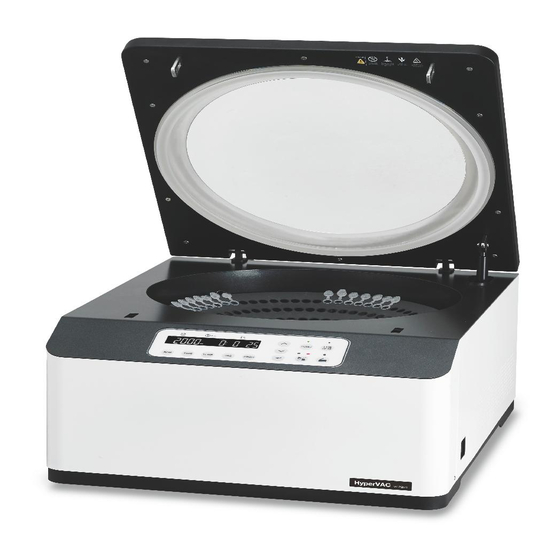
2. Product Description 2.1 Product Description [HVC-2124] [HVC-2200] 7 / 29 Technical Support : +82-2-3452-8966 / techsupport@ihanil.com... -
Page 8: Delivery Package
2. Product Description 2.2 Delivery Package · Check all parts for damage that may have occurred during transportation. · Check the delivery for completeness. - Hyper VAC 2124/2200 - AC Power cable - Emergency release tool 8 / 29 www.ihanil.com... -
Page 9: Technical Specifiations
2. Product Description 2.3 Technical Specifiations HVC-2124 HVC-2200 Max. RPM 200 ~ 2,000 RPM 200 ~ 2,000 RPM 120 x 1.5 / 2.0 ml microtubes Max. Capacity 200 x 1.5 / 2.0 ml microtubes 48 x 1.5 / 2.0 ml + 76 x 0.5 ml 12 x 50 mL microtubes Auto Start / Stop... -
Page 10: Installation
3. Installation 3.1 Unpacking 1. Open the box and lift out the device carefully. 2. The system should be horizontally lifted up on the flat table. 3. Insert the Emergency Lid Release Tool into ‘Opening for Emergency Lid Release’ on the left side of the main body. -
Page 11: Switching On The Device
3. Installation 3.3 Switching On the Device 1. After connecting the AC Power cord to the mains power on the right back of the device, turn on the Earth Leakage Circuit Breaker. ▶ Check the power on. 2. Turn on the main power on the right side of the device. 3.4 Opening the Lid 1. -
Page 12: Emergency Lid Release
3. Installation 3.5 Emergency Lid Release - Manual lid opening should be performed only when spinning is completely stopped. Otherwise, harmful damage can be accompanied. - After opening the lid manually, it is recommended to wait until the main power turns back on. For emergency lid release, you can use the Emergency Lid Release Tool only when the device is completely stopped. -
Page 13: Installing/Removing The Rotor
3. Installation 3.6 Installing/Removing the Rotor 1. Before installing a rotor, clean the motor shaft and chamber with soft dry towel. 2. Load a rotor into the motor shaft. Lock it with the Locking Nut. - To install the rotor: Rotate the locking nut clockwise until tightly assembled. - To remove the rotor: Rotate the locking nut counterclockwise. -
Page 14: Positioning Of Sample Tubes
3. Installation 3.7 Positioning of Sample Tubes - If it is hard to make balance with the samples, please employ control tubes. Otherwise, it may bring about noise or vibration, which may lead to damaging the device. Correct Arrangement Wrong Usage of Tubes Different Caps Different Volume Different Density... -
Page 15: Operation
4. Operation 4.1 Key Functions of Control Panel [Main Display] ⑨ ⑩ Down ① ② ③ ④ ⑤ ⑥ ⑦ ⑧ ① Use to set the of RPM (200 ~ 2,000 rpm) ② Use to set time, available range up to 23 hr 59 min or continuous Use to set temperature (RT ~60 ℃) . - Page 16 4. Operation 4.1 Key Functions of Control Panel [Sub Display] Sub Display appears upon the button after setting the operating conditions. - Sub Display function is for manual ON/OFF of vacuum pump. But it can be used only when the machine is not operating. - Normally, adjustment of the Sub Display is not used for operation but for Emergency Lid Release in any emergency conditions.
-
Page 17: Setting The Rpm
4. Operation 4.2 Setting the RPM 1. Press the button once. - RPM mode - RPM LED flickers on the display window. 2. Press the button to change input value and then press the button to complete the setting. ▶ Speed setting unit (display unit): 10 rpm (1 rpm) ▶... -
Page 18: Saving A Program
4. Operation 4.5 Saving a Program 1. Set parameters. (Refer to 4-2 ~ 4-4.) 2. Press the button longer than 3 seconds. - Check the message of “PROGRAM SAVE: ##” on the display window. 3. Press the buttons to change input Program number. - Save up to 100 programs. -
Page 19: Operation Sequence
4. Operation 4.8 Operation Sequence [Detailed Sequences for Operation] 1. Fill the chamber of Drip Catcher kit with ice. 2. Turn on the centrifuge and the vacuum pump. 3. Set the parameters according to your preferences. (RPM / TIME / TEMP) 4. - Page 20 4. Operation 4.8 Operation Sequence [Operating Status for Each Part (VacPump / Release / Heater)] VacPump Release Heater Power ON (Start status: default setting) VacPump Release Heater Setting Temperature and Running Device (~20 min.) VacPump Release Heater Until reaching the set RPM (Refer to VacPump Release Heater...
-
Page 21: Maintenance
5. Maintenance 5.1 Outer Part of Device 1. Clean the outside of the device with dry soft cloth. If necessary, dip the cloth in neutral detergent and clean contaminated area. Keep the device completely dry after cleaning. 2. Do not use any volatile chemicals such as alcohol and benzene, etc. 3. - Page 22 5. Maintenance 5.4 Rotor 1. If any parts become contaminated with samples, clean the rotor with soft wet cloth and keep them dry. 2. Be careful not to make scratches inside or on the surface of rotors. Any small scratches can cause corrosion of the rotor and big damage to the device.
-
Page 23: Troubleshooting
6. Troubleshooting 6.1 Possible Problems If any problems occur in the device, please check the following list before contact your local Hanil Scientific Inc. partner or Hanil Scientific Inc. Symptom Recommended Action Connect the AC Power cord and make sure that the line is completely Power failure connected between the device and power outlet. -
Page 24: Error Codes
6. Troubleshooting 6.2 Error Codes Error Possible Causes Solution - Turn off and on the main power to check the device. Error 1 RPM Sensor - If the error code keeps coming up, please contact us. - If lid opens while the device running or the device has any trouble in lid sensor, this message may come up. - Page 25 ▶ Any wire disconnection or tuning of the device must be performed only by a service engineer who is authorized by Hanil Scientific Inc. ▶ Before contact Hanil Service, please check the serial number of the device indicated on the product label.
- Page 26 7. Rotors & Accessories [ Rotors for HVC-2124 (1) ] Hole Tube/ Max. Tube Cooling Trap Sleeve Diameter Plate Type Capacity (mm) HRV-m0.5/2.0-124 48 x 1.5/2.0 1.5 or 2.0 mL 11.1 mL + /0.5 mL 76 x 0.5 mL HRV-m2.0-120 120 x 1.5/2.0 1.5/2.0 mL 11.1...
-
Page 27: Ordering Information
7. Ordering Information [ Rotors for HVC-2124 (2) ] Tube/ Max. Tube Cooling Trap Plate Type Capacity HRV-10-18 10 mL 18 x 10 mL vial tube HRV-10-32 10 mL 32 x 10 mL HRV-15c-12 15 mL conical 12 x 15 mL conical HRV-20-12 20 mL 12 x 20 mL vial tube... - Page 28 7. Ordering Information [ Rotors for HVC-2200 (1) ] Hole Tube/ Max. Tube Cooling Trap Sleeve Diameter Plate Type Capacity (mm) HRV-m2.0-200 48 x 1.5/2.0 1.5 or 2.0 mL 11.1 mL + /0.5 mL 76 x 0.5 mL HRV-15-48 Incl. 48 ea x HLV-15 15 mL HLV-15 48 x 15 mL...
- Page 29 7. Ordering Information [ Rotors for HVC-2200 (2) ] Tube/ Cooling Trap Sleeve Plate Type HRV-5-192 5 mL 192 x 5 mL HRV-8-60 8 mL 60 x 8 mL vial tube HRV-15c-24 15 mL Conical 24 x 15 mL conical HRV-30-24 2 4 x 3 0 m L v i a l 30 mL...
- Page 30 MEMO...
- Page 32 RECYCLABLE...
Need help?
Do you have a question about the HyperVAC HVC-2124 and is the answer not in the manual?
Questions and answers