
Related Manuals for ADLINK Technology AmITX-CF-G


Summary of Contents for ADLINK Technology AmITX-CF-G
- Page 1 AmITX-CF-G User’s Manual Mini-ITX Embedded Motherboard with and 9 Gen. Intel® Core™ i7/i5/i3 Processors and Intel® Q370/H310 Chipset Manual Rev.: Revision Date: September 23, 2022 Part Number: 50M-00093-1000...
- Page 2 Preface Copyright Copyright 2022 ADLINK Technology, Inc. This document contains proprietary information protected by copyright. All rights are reserved. No part of this manual may be reproduced by any mechanical, electronic, or other means in any form without prior written permission of the manufacturer.
-
Page 3: Table Of Contents
AmITX-CF-G Table of Contents Preface ..........................ii Table of Contents ......................iii List of Figures ........................v List of Tables ........................vi Introduction ........................ 1 1.1. Packing List ........................1 1.2. Optional Accessories ...................... 1 Specifications ......................3 2.1. Core System ........................3 2.2. -
Page 4: Preface
7.5. PCI Interrupt Routing Map .................... 43 7.6. SMBus Slave Address ....................43 BIOS Setup ....................... 45 8.1. BIOS Setup Menu ......................45 8.2. Menu Structure......................46 8.3. Main Menu ........................47 8.4. Advanced ........................47 8.5. Chipset .......................... 56 8.6. -
Page 5: List Of Figures
AmITX-CF-G List of Figures Figure 1: AmITX-CF-G Functional Block Diagram .................11 Figure 2: AmITX-CF-G Rear I/O ......................13 Figure 3: AmITX-CF-G Component-Side Connectors ................13 Figure 4: AmITX-CF-G Mechanical Dimensions ..................14 Figure 5: Jumper and Switch Locations ....................29 Preface... - Page 6 List of Tables Table 1: AmITX-CF-G Model Numbers ....................1 Table 2: AmITX-CF-G Onboard Connector Information .................32 Table 3: SEMA Onboard Voltage Monitor ....................35 Table 4: SEMA BMC Status ........................36 Table 5: SEMA Exception Codes ......................36 Table 6: SEMA BMC Flags........................37 Table 7: System Memory Map .......................39...
-
Page 7: Introduction
The AmITX-CF-G features three DisplayPorts, dual Gigabit Ethernet ports, USB 3.0 ports, USB 2.0 ports, SATA 6 Gb/s ports, and High Definition Audio with 7.1 channels. Expansion is provided by one PCIe x16, one PCIe x1, one M.2 and one mini-PCIe slot. - Page 8 This page intentionally left blank. Introduction...
-
Page 9: Specifications
AmITX-CF-G 2. Specifications 2.1. Core System Embedded 9 Gen. Intel® Core™ i7/i5/i3 and Pentium®/Celeron® Processor, LGA1151 socket Intel® Core™ i7-9700TE Processor, 8C, 1.8/3.8GHz, 12M, 35W Intel® Core™ i7-9700E Processor, 8C, 2.6/4.4GHz, 12M, 65W Intel® Core™ i5-9500TE Processor, 6C, 2.2/3.6GHz, 9M, 35W Intel®... -
Page 10: Internal Headers And Connectors
2.4. Internal Headers and Connectors PCI Express Slots PCIe x16 (Gen3) PCIe x1 (Gen2) 1x full-size Mini-PCIe slot (Q370: PCIe x1, mSATA and USB 2.0 / H310: PCIe x1) 1x M.2 (M key, 2242, NVMe support; H310: PCIe x1 Gen2 signal) 2x USB 3.0 onboard header (Q370) 1x USB 2.0 onboard header (H310) 1x USB 3.0 vertical connector (H310 only supports USB2.0) -
Page 11: Video
AmITX-CF-G 2.7. Video GPU Feature Support Intel® 9th generation LP graphics core architecture with up to 18 execution units supporting DirectX 11/12, OGL4.3/4.4, and up to three independent, simultaneous displays 3x DisplayPort v1.2 with resolution up to 4096 x 2304 @ 60Hz... - Page 12 2.11.1. Power Consumption ATX mode (with standard power supply 24-pin) Processor i3-8100T 3.1 35W i5-8500T 2.10 35W i7-9700TE 1.8 35W i5-9500E 3.0 65W i7-8700 3.2 65W Chipset Q370 Q370 Q370 Q370 Q370 Memory 16G 2400MHz 16G 2400MHz 16G 2400MHz 16G 2400MHz 16G 2400MHz Graphics Q370...
- Page 13 AmITX-CF-G ATX mode (with standard power supply 24-pin) Windows Max mode/Enable EIST/Enable Turbo boost 3.3A(A)orange 0.12 0.09 0.11 5V(A)red 0.17 0.16 0.18 0.16 0.17 +12V(A)yellow 13.65 16.31 16.86 22.33 24.13 5VSB(A)purple 0.01 0.01 0.02 0.01 0.01 Power 165.03 196.9 203.716 269.107...
- Page 14 ATX mode (with standard power supply 24-pin) System S5 mode with ECO enabled 3.3A(A)orange 0.01 0.01 0.01 0.01 0.02 5V(A)red 0.01 0.01 0.01 0.01 0.02 +12V(A)yellow 0.01 0.01 0.01 0.01 5VSB(A)purple 0.02 0.02 0.03 0.04 0.01 Power 0.303 0.303 0.353 0.403 0.216 Consumption(W)
- Page 15 AmITX-CF-G ATX mode (with 12V adapter) Windows Typical mode/Disable EIST/Disable Turbo boost 3.3A(A) 5V(A) 12V(A) 12.71 13.03 13.48 15.6 15.99 5VSB(A) Power 152.52 156.36 161.76 187.2 191.88 Consumption(W) Windows Max mode/Enable EIST/Enable Turbo boost 3.3A(A) 5V(A) 12V(A) 14.21 16.12 18.31 21.6...
-
Page 16: Temperatures
ATX mode (with 12V adapter) System S5 mode with ECO disable 3.3A(A) 5V(A) 12V(A) 0.15 0.16 0.12 0.15 0.13 5VSB(A) Power 1.92 1.44 1.56 Consumption(W) System S5 mode with ECO Enable 3.3A(A) 5V(A) 12V(A) 0.07 0.07 0.06 0.07 0.09 5VSB(A) Power 0.84 0.84... -
Page 17: Functional Block Diagram
Connector COM3 RS232 Super I/O Fintek Header ALC81866 COM4 RS232 Header 2x RS232/CCTalk COM5&6 Header TPM 2.0 (SLB9665) Figure 1: AmITX-CF-G Functional Block Diagram Note: Full-size Mini-PCIe slot (Q370: PCIe x1, mSATA and USB 2.0 / H310: PCIe x1) Specifications... - Page 18 This page intentionally left blank. Specifications...
-
Page 19: Mechanical Layout
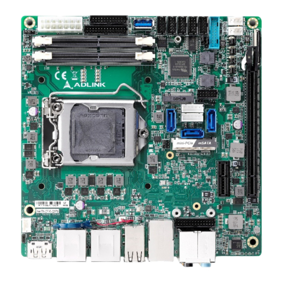
3. Mechanical Layout 3.1. Connector Locations 3.1.1. Rear I/O Connectors USB 3.0 USB 3.0 USB 2.0 LAN 1 Audio LAN 2 Figure 2: AmITX-CF-G Rear I/O 3.1.2. Component-Side Connectors Audio Header CPU Fan Mini PCIe / mSATA PCIe x16 SATA1/2/3 PCIe x1 SATA Power Con. -
Page 20: Mechanical Dimensions
3.2. Mechanical Dimensions Top View Side View Dimensions: mm Figure 4: AmITX-CF-G Mechanical Dimensions Mechanical Layout... -
Page 21: Thermal Solutions
In no event may the chassis ventilation holes be obstructed. Always ensure that sufficient clearance (at least 50 mm to each direction except fo the base) exists around the cooling vents for unrestricted airflow. Failure to comply with this instruction could result in damage to the ADi-SAXX or AmITX-CF-G. Mechanical Layout... - Page 22 This page intentionally left blank. Mechanical Layout...
-
Page 23: Connectors And Jumpers
AmITX-CF-G 4. Connectors and Jumpers See Section 3.1 Connector Locations 4.1. Rear IO Connectors 4.1.1. DisplayPort Connectors Three DisplayPort v1.2 specification connectors up to 3840x2160 @ 60 Hz Pin # Signal Pin # Signal CN_DP0_P Ground CN_DP0_N CN_DP1_P Ground CN_DP1_N... - Page 24 LED1 (Link/Activity) LED2 (Speed) Status Description Status Description No Link 10 Mb connection Green Link Orange 100 Mb connection Orange Data Activity Blinking 1 Gb connection 4.1.3. USB Connectors 4x USB 3.0, 4x USB 2.0 5V supply for external devices ...
-
Page 25: Internal Connectors
AmITX-CF-G 4.2. Internal Connectors 4.2.1. ATX Power Connector (ATX_PWR, proprietary) AmITX-CF-G supports a proprietary internal ATX Power Connector (ATX_PWR). An adapter cable is provided for conection to a standard ATX power supply. Pin # Signal Pin # Signal SB5V P_OK... - Page 26 4.2.2. SATA Connectors (SATA1/2/3) Three SATA 6 Gbps ports are available on the AmITX-CF-G. • Option function: Jumper select NA/3.3V/5V for SATA1 and SATA2 to deliver power by SATA pin 7; default is Pin # Signal N/A(default), (option)SATA1/2 SATA DOM 4.2.3.
- Page 27 AmITX-CF-G 4.2.4. USB Headers 5V/SB5V: 5V supplies for external devices. SB5V is supplied during power-down to allow wakeup on USB device activity during S3~S4 state. H310: 1xUSB2.0: Pin # Signal Pin # Signal USB2_10_14_PWR 2 USB2_10_14_PWR USB2_P14 USB2_N14 USB Cable (optional): USB 2.0 Header to 2x Female Type-A Cable (length 200mm), P/N: 30-20874-1000...
- Page 28 USB Cable (optional): USB 3.0 Header to 2x Female Type-A Cable (length 200mm), P/N: 30-20963-0000 4.2.5. Audio Header 2x13-pin 2.0 pitch standard wafer connector Note: Signals shared with Audio Header on Rear I/O Signal Pin # Pin # Signal LFE-OUT CEN-OUT AAGND AAGND...
- Page 29 AmITX-CF-G 4.2.7. Serial COM Port Connectors Six internal Serial Ports (SER1-6) Serial Port Functions SER1 Supports RS-232 / RS-422 / RS-485, 5V/12V power support by jumper select (JPS3P, default NC). SWS1M: Switch for mode selection of SER1 (default RS-232). SER2...
- Page 30 RS-232 (SER5_6 only) Pin # Signal Pin # Signal RxD5 RTS5 TxD5 CTS5 RxD6 RTS6 TxD6 CTS6 ccTalk (SER5_6 only) Pin # Signal Pin # Signal ccTalk_RX5 2 — ccTalk_TX5 — ccTalk_RX6 8 — ccTalk_TX6 — SER1 Mode Switch (SWS1M) SWS1M (SER1 Mode Select) RS-232 RS-422...
- Page 31 AmITX-CF-G 4.2.8. Front Panel Header 2x12-pin 2.0 pitch standard wafer connector The front panel connector provides Audio Mic-In / Line Out, ATX power switch, Reset, HDD LED, and SUS LED (System Power LED). Pin # Signal Ioh/ Iol Type Note Pin # Signal...
- Page 32 4.2.9. Feature Header 2x14-pin 2.0 pitch standard wafer connector The feature connector provides Case Open, I2C, SMBus, and GPIO (10pin). Signal Description TEMPS Analogue temp sensor, connect to analog input of BMC EXT_BAT Connect to RTC power CASE_OPEN# Any time case open occurs, system will notice/show case open alert in POST during the next boot.
- Page 33 AmITX-CF-G Signal Description Serial Clock SB3V3 3.3V Standby Voltage power line. Normally output power, but when Motherboard is turned off then the on-board SPI Flash can be 3.3V power sourced via this pin. CS0# CS0# Chip Select 0, active low.
- Page 34 4.2.11. DB40 Debug Connector FPC Connector Type: FCI 59GF Flex 10042867 Interface Signal Remark Interface Signal Remark VCC_SPI_IN SPI Power Input from TXD6 flash tool to module. HW Program Program need add MOS FET to interface interface switch SPI power for SPI (continued) RXD6 SPI_BIOS_CS0#...
-
Page 35: Jumper And Switch Settings
AmITX-CF-G 4.3. Jumper and Switch Settings CMOS JPS3P1 MPCIE_S JPS4P1 JPS6M2 JPS6M1 JPS5M2 ATX/AT Mode JPS5M1 Jumper (JPATX) SER1 PWR SEL BIOS WP SWS1M (JPS1P) Figure 5: Jumper and Switch Locations 4.3.1. ATX/AT Mode Jumper Selection (JPATX) ATX/AT Mode ATX (default) 4.3.2. - Page 36 4.3.3. COM Port (SER1) Mode Selection Switch (SWS1M) SWS1M (SER1 Mode Select) RS-232 RS-422 RS-485 (default) 4.3.4. COM Port (SER1) Power Selection Jumper (JPS1P) JPS1P SER1 Power NC (default) 4.3.5. SER5-6 Mode Select (JPS5M1/ JPS5M2 ; JPS6M1/ JPS6M2) SER5-6 Mode Select RS-232 (default) ccTalk 4.3.6.
- Page 37 AmITX-CF-G 4.3.7. BIOS Write Protect Selection (BIOS_WP) BIOS_WP BIOS Write Protect Selection Control(Default) Enable Note: There will be the following limitations with write protect enabled: A. S3 and S4 will not be supported under OS. B. IAMT cannot be supported C.
-
Page 38: Onboard Connector Information
4.4. Onboard Connector Information Table 2: AmITX-CF-G Onboard Connector Information Onboard Connector Mating Connector Connector Manufacturer Part No. Manufacturer Part No. ADLINK Cable YY-1970H-2*5P 30-20876- COM Port SER1-6 21-65310-2050 YOUNG YAK (PH2.0) 0000(optional) E.C.I 5016H- 30-20872- ATX power ATX_PW Molex 20-65703-2070 E.C.I... -
Page 39: Driver Installation
AmITX-CF-G 5. Driver Installation Drivers can be downloaded through the following link: https://www.adlinktech.com/en/Industrial_Motherboards_SBCs_Mini-ITX_Embedded_Boards Driver Installation... - Page 40 This page intentionally left blank. Driver Installation...
-
Page 41: Smart Embedded Management Agent (Sema)
AmITX-CF-G 6. Smart Embedded Management Agent (SEMA) The onboard microcontroller (BMC) implements power sequencing and Smart Embedded Management Agent (SEMA) functionality. The microcontroller communicates via the System Management Bus with the CPU/chipset. The following functions are implemented. • Total operating hours counter. Counts the number of hours the module has been run in minutes. -
Page 42: Table 4: Sema Bmc Status
3 samples not influenced by the read access. Main Current = (MSB_n<<8 + LSB_n) x 8.06mA 6.1.3. BMC Status This register shows the status of BMC controlled signals on the AmITX-CF-G. Table 4: SEMA BMC Status Status Bit Signal... -
Page 43: Table 6: Sema Bmc Flags
AmITX-CF-G 6.1.5. BMC Flags The BMC Flags register returns the last detected Exception Code since power-up and shows the BIOS in use and the power mode. Table 6: SEMA BMC Flags Description [ 0 ~ 4 ] Exception Code [ 6 ]... - Page 44 This page intentionally left blank. Smart Embedded Management Agent (SEMA)
-
Page 45: System Resources
AmITX-CF-G 7. System Resources 7.1. System Memory Map Table 7: System Memory Map Address Range (decimal) Address Range (hex) Size Description (4GB-2MB) FFE00000 – FFFFFFFF 2 MB High BIOS Area (4GB-18MB) – (4GB-17MB-1) FEE00000 – FEEFFFFF 1 MB MSI Interrupts (4GB-20MB) –... -
Page 46: Interrupt Request (Irq) Lines
Hex Range Device 380h – 3AFh Available 4D0h Master PIC Edge/Level Trigger register 4D1h Slave PIC Edge/Level Trigger register 0A00h – 0A2Fh Reserved for SIO functions base address (ex: PME/GPIO etc.) 0CF8h – 0CFBh PCI configuration address register (32bit I/O only) 0CF9h Reset Controller register (8 bit I/O) 0CFCh –... -
Page 47: Table 10: Irq Lines Apic Mode
AmITX-CF-G IRQ# Typical Interrupt Resource Connected to Pin Available Math Processor Generic Intel SD Host Controller Note Note (1): These IRQs can be used for PCI devices when onboard device is disabled. 7.3.2. IRQ Lines APIC Mode Table 10: IRQ Lines APIC Mode... -
Page 48: Pci Configuration Space Map
7.4. PCI Configuration Space Map Table 11: PCI Configuration Space Map Device Function Routing Description Number Number Number Intel Host Bridge Intel PEG port Internal Intel I.G.D. Internal System device Internal xHCI Controller Internal Data Acquisition Internal Intel Management Engine Interface #1 Internal Intel AHCI controller Internal... -
Page 49: Pci Interrupt Routing Map
AmITX-CF-G 7.5. PCI Interrupt Routing Map Table 12: PCI Interrupt Routing Map P.E.G Intel PEG Intel System xHCI Data port I.G.D. device Controller Acquisition Line Root Port Int0 INTA:16 INTA:16 INTA:16 INTA:16 INTA:16 INTA:16 Int1 INTB:17 INTB:17 INTB:17 INTB:17 INTB:17... - Page 50 This page intentionally left blank. System Resources...
-
Page 51: Bios Setup
8. BIOS Setup The AmITX-CF-G is provided with a pre-installed AMI EFI BIOS firmware configurable via a setup utility that is invoked during the BIOS boot phase. The BIOS configuration is stored in the NVRAM part of the SPI Flash chip. All settings will remain valid after the system is powered down. -
Page 52: Menu Structure
8.2. Menu Structure This section presents the six primary menus of the BIOS Setup Utility. Use the following table as a quick reference for the contents of the BIOS Setup Utility. The subsections in this section describe the submenus and setting options for each menu item. -
Page 53: Main Menu
AmITX-CF-G 8.3. Main Menu The Main Menu provides read-only information about your system and also allows you to set the System Date and Time. Refer to the tables below for details of the submenus and settings. 8.3.1. Main Feature Options... - Page 54 Feature Options Description Package C State Limit C0/C1 Maximum Package C State Limit Setting. Cpu Default: Leaves to Factory default value.Auto: Initializes to deepest available Package C State Limit. CPU Default Auto 8.4.2. Advanced > Power Management Feature Options Description Power Management ►...
- Page 55 AmITX-CF-G 8.4.4. Advanced > Thermal Management Feature Options Description Thermal Management ► Submenu Thermal Management Info only CPU Temperature Board Temperatures Info only CPU Fan Speed Info only Display CPU fan speed System Fan1 Speed Info only Display system fan 1 speed...
- Page 56 Info only IO Address & IRQ Info COM6 Device Settings Info only IO Address & IRQ Info Note: COM1-6 in BIOS correspond to the serial ports SER1-6 on the AmITX-CF-G board. 8.4.7. Advanced > Serial Console Redirection Feature Options Description Serial Console Redirection ►...
- Page 57 AmITX-CF-G Feature Options Description Serial Console Redirection ► Submenu Serial Console Redirection COM5 Info only Console Redirection Disabled Console Redirection Enable or Disable. Enabled Console Redirection Settings ► Submenu The settings specify how the host computer and the remote computer (which the user is using) will (see Section 8.4.7.1)
- Page 58 Feature Options Description VT-UTF8 Combo Key Support Disabled Enable VT-UTF8 Combination Key Support for ANSI/VT100 terminals Enabled Recorder Mode Disabled With this mode enabled only text will be sent. This is to capture Terminal data. Enabled Disabled Resolution 100x31 Enables or disables extended terminal resolution Enabled VT100 Putty KeyPad...
- Page 59 AmITX-CF-G Feature Options Description Storage Hierarchy Enabled Enable or Disable Storage Hierarchy Disabled Endorsement Hierarchy Enabled Enable or Disable Endorsement Hierarchy Disabled TPM2.0 UEFI Spec Version TCG_1_2 Select the TCG2 Spec Version Support, TCG_2 TCG_1_2: the Compatible mode for Win8/Win10,...
- Page 60 8.4.13. Advanced > USB Configuration Feature Options Description USB Configuration ► Submenu USB Configuration USB Configuration Info only USB Module version Info only USB Controllers: Info only USB Devices: Info only XHCI Hand-off Disabled This is a workaround for OSes without XHCI hand- off support.
- Page 61 AmITX-CF-G 8.4.16. Advanced > Realtek PCIe GBE Family Controller (MAC address1) Feature Options Description Realtek PCIe GBE Family Realtek PCIe GBE Family Controller (MAC Submenu Controller (MAC address1) ► address1) Driver Information Info only Device Information Info only Patent Information Info only 8.4.17.
-
Page 62: Chipset
8.5. Chipset 8.5.1. Chipset > System Agent (SA) Configuration Feature Options Description System Agent (SA) Configuration ► Submenu System Agent (SA) Configuration System Agent (SA) Configuration Info only SA PCIe Code Version Info only VT-d Info only Memory Configuration ► Submenu Memory Configuration parameters Memory Configuration... - Page 63 AmITX-CF-G Feature Options Description PEG Port Configuration Info only VT-d Disabled Enable or Disable VT-d capability Enabled Disabled Above 4GB MMIO BIOS Enable or disable above 4GB MemoryMappedIO BIOS assignment assignment This is enabled automatically when Enabled Aperture Size is set to 2048MB.
- Page 64 Feature Options Description SATA Controller Speed Default Indicates the maximum speed the SATA controller can support. Gen1 Gen2 Gen3 Serial ATA Port 0 Info only Port 0 Disabled Enable or Disable SATA Port Enabled Disabled Hot Plug Designates this port as Hot Pluggable. Enabled Serial ATA Port 1 Info only...
-
Page 65: Security
AmITX-CF-G Feature Options Description Audio Output Selection AD7.1 for Audio Jack AD7.1 or AD5.1 for Audio Jack AD5.1 for Audio Jack 8.6. Security Feature Options Description Password Description Info only Administrator Password Enter password User Password Enter password Secure Boot menu ►... - Page 66 Feature Options Description Boot Option #2 Hard Disk Sets the system boot order CD/DVD USB Hard Disk USB CD/DVD USB Key USB Floppy USB Lan Network Disabled Boot Option #3 Hard Disk Sets the system boot order CD/DVD USB Hard Disk USB CD/DVD USB Key USB Floppy...
-
Page 67: Save & Exit
AmITX-CF-G Feature Options Description Boot Option #7 Hard Disk Sets the system boot order CD/DVD USB Hard Disk USB CD/DVD USB Key USB Floppy USB Lan Network Disabled Boot Option #8 Hard Disk Sets the system boot order CD/DVD USB Hard Disk... -
Page 68: Safety Instructions
Safety Instructions Read and follow all instructions marked on the product and in the documentation before you operate your system. Retain all safety and operating instructions for future use. • Please read these safety instructions carefully. • Please keep this User‘s Manual for later reference. •... -
Page 69: Getting Service
San Jose, CA 95119-1208, USA Tel: +1-408-360-0200 Toll Free: +1-800-966-5200 (USA only) Fax: +1-408-600-1189 Email: info@adlinktech.com ADLINK Technology (China) Co., Ltd. Address: 300 Fang Chun Rd., Zhangjiang Hi-Tech Park, Pudong New Area Shanghai, 201203 China Tel: +86-21-5132-8988 Fax: +86-21-5132-3588 Email: market@adlinktech.com...
Need help?
Do you have a question about the AmITX-CF-G and is the answer not in the manual?
Questions and answers