
Related Manuals for ADLINK Technology AmITX-HL-G


Summary of Contents for ADLINK Technology AmITX-HL-G
- Page 1 AmITX-HL-G User’s Manual Mini-ITX Motherboard with 4th Gen Intel Core™ i7/i5/i3 Processor ® and Intel Q87/H81 Chipset ® Manual Revision: 1.00 Revision Date: November 24, 2015 Part Number: 50-1X012-1000...
-
Page 2: Revision History
Revision History Revision Description Date 1.00 Initial release 2015-11-24 Page 2 AmITX-HL-G... -
Page 3: Preface
When products are at their end of life, our customers are encouraged to dispose of them in accordance with the product disposal and/or recovery programs prescribed by their nation or company. AmITX-HL-G is a RoHS compliant and leadfree product Trademarks Product names mentioned herein are used for identification purposes only and may be trademarks and/or registered trademarks of their respective companies. -
Page 4: Table Of Contents
Rear IO Connectors......................18 4.1.1. DisplayPort ............................18 4.1.2. USB Connectors ..........................18 4.1.3. Ethernet Connectors (LAN1, LAN2) ....................19 4.1.4. Audio Connectors ..........................19 4.2. Internal Connectors ......................20 4.2.1. ATX Power Connector (ATX_PWR, proprietary) ................20 4.2.2. SATA Connectors (SATA0/1/2) ......................21 Page 4 AmITX-HL-G... - Page 5 BMC Flags ............................39 System Resources ....................40 7.1. System Memory Map ......................40 7.2. Direct Memory Access Channels ..................40 7.3. I/O Map..........................40 7.3.1. I/O Map .............................40 7.3.2. IRQ Lines PIC mode..........................42 7.3.3. IRQ Lines APIC mode .........................43 AmITX-HL-G Page 5...
- Page 6 Serial Port Console ..........................59 8.3.12. Network............................60 8.3.13. Security............................61 8.3.14. Miscellaneous..........................61 8.4. Boot ............................ 62 8.4.1. Boot Configuration ..........................62 8.5. Security ..........................63 8.5.1. Password Description ........................63 8.6. Save & Exit .......................... 63 Safety Instructions ...................... 64 Getting Service ......................65 Page 6 AmITX-HL-G...
-
Page 7: Introduction
The AmITX-HL-G features three DisplayPorts, dual Gigabit Ethernet ports, USB 3.0 ports, USB 2.0 ports, SATA 6 Gb/s ports, and High Definition Audio with 7.1 channels. Expansion is provided by one PCIe x16, one PCIe x1, and two mini-PCIe slots. The onboard feature connector provides GPIO, SMBus, and I C support. -
Page 8: Specifications
SATA: 3x SATA ports (Q87 supports 3x SATA 6 Gb/s, H81 supports 2x SATA 6 Gb/s, 1x SATA 3 Gb/s) SATA Power Connector Serial: 3x RS-232 headers, 1x RS-232/422/485 headers with 5V power (12V by BOM option) LVDS (optional): Supports non-EDID type LCD panels only Front Panel Header Audio Header Feature Connector Header Page 8 AmITX-HL-G... -
Page 9: Form Factor
Intel PHY: Intel® i218LM (PHY) Ethernet controller • Supports Intel® AMT 9.0 on Q87 • Supports Intel® vPro™ on Q87 Intel MAC/PHY: Intel® i211AT (MAC/PHY) Ethernet controller Interface: 10/100/1000 GbE connection 2.10. Trusted Platform Module (TPM) Chipset: Atmel AT97SC3204 (optional) Type: TPM1.2 AmITX-HL-G Page 9... -
Page 10: Power Specification
MIL-STD-202F, Method 213B, Table 213-I, Condition A and Method 214A, Table 214-I, Condition D HALT: Thermal Stress, Vibration Stress, Thermal Shock and Combined Test 2.14. Operating Systems Standard Support: Windows 7/8 32/64-bit, Linux 32/64-bit Extended Support (BSP): WES7, WE8S, Linux, VxWorks Page 10 AmITX-HL-G... -
Page 11: Power Consumption
Windows 7 (Idle) 1.18/12.05 14.22 1.32/12.09 15.96 Windows 7 (Typical) 3.63/12.06 43.78 3.25/12.08 39.26 Windows 7 (Max loading) 7.27/11.96 86.95 6.66/11.97 79.72 Notes: (1) ACPI/S1 mode not supported by BIOS. (2) ECO mode not supported by BIOS. AmITX-HL-G Page 11... - Page 12 Windows 7 (Idle) 1.07/12.1 12.95 1.17/12.1 14.16 Windows 7 (Typical) 2.52/12.18 30.69 2.43/12.18 29.6 Windows 7 (Max loading) 4.73/12.08 57.14 4.75/12.08 57.38 Notes: (1) ACPI/S1 mode not supported by BIOS. (2) ECO mode not supported by BIOS. Page 12 AmITX-HL-G...
-
Page 13: Functional Diagram
IT8783 SPI 0/1 SPI0 SPI1 socket PS/2 Failsafe SPI0 switch CPU Fan Atmel SMbus System Fan1 System Fan2 Temp input for System Fan Sensor GPIO Feature Connector GPIO System Signals Rear I/O Connectors Internal Connectors Functional Components AmITX-HL-G Page 13... -
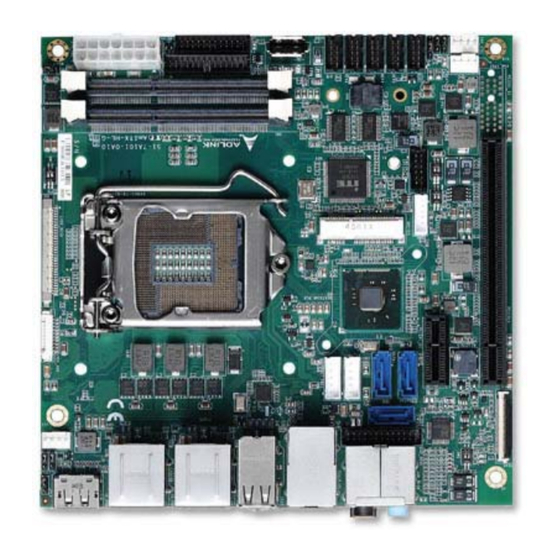
Page 14: Mechanical Layout
CPU Fan PCIe x16 Mini PCIe Audio Header LVDS AUX SPI Socket LVDS SPI Header USB Vertical Connector PS/2 KB/MS 2x SODIMM Feature Connector USB 2.0 3x RS-232 Front Panel Connector 1x RS-232/422/485 ATX/AT Power System Fans Page 14 AmITX-HL-G... -
Page 15: Mechanical Dimensions
3.2. Mechanical Dimensions Top View Dimensions: mm All tolerances ±0.2mm AmITX-HL-G Page 15... - Page 16 Side View Dimensions: mm All tolerances ±0.2mm Page 16 AmITX-HL-G...
-
Page 17: Thermal Solutions
P/N: 32-20513-0000 LGA1150 CPU Cooler, H=46.05mm, 45W Standard Temp.: 0°C to 60°C P/N: 32-20512-0000 LGA1150 CPU Cooler, H=50.2mm, 95W Standard Temp.: 0°C to 60°C P/N: 32-20113-0000 LGA1150 CPU Cooler, H=61.4mm, 95W Standard Temp.: 0°C to 60°C P/N: 32-20495-0000 AmITX-HL-G Page 17... -
Page 18: Connectors And Jumpers
5Vsb is supplied during power down to allow wakeup on USB device activity during S3~S4 state 1.5A for device power supply protected by a resettable 2A fuse Pin # Signal UV0- UV0+ Pin # Signal USB3.0_P5VA USB2_CMAN USB2_CMAP USB3A_CMRXN USB3A_CMRXP USB3A_CMTXN USB3A_CMTXP Page 18 AmITX-HL-G... -
Page 19: Ethernet Connectors (Lan1, Lan2)
Green 100 Mb connection Orange Linked Orange 1 Gb connection Blinking Data Activity 4.1.4. Audio Connectors 7.1 channel audio via 5 jacks and S/PDIF output on rear I/O Intel® High Definition Audio on chipset Realtek ALC886 codec AmITX-HL-G Page 19... -
Page 20: Internal Connectors
4.2. Internal Connectors 4.2.1. ATX Power Connector (ATX_PWR, proprietary) AmITX-HL-G supports a proprietary internal ATX Power Connector (ATX_PWR). An adapter cable is provided for connection to a standard ATX power supply. Pin # Signal Pin # Signal SB5V P_OK PS_ON#... -
Page 21: Sata Connectors (Sata0/1/2)
4.2.2. SATA Connectors (SATA0/1/2) Three SATA 6 Gbps ports are available on the AmITX-HL-G (H81: 2x SATA 6 Gbps and 1x SATA 3 Gbps). Pin # Signal 4.2.3. SATA Power Connector (ST_PWR1/2) Pin # Signal 3.3V SATA Power Cable: ADLINK Part. No.: 30-20875-0000 (length 200 mm) -
Page 22: Usb Header
5V/SB5V: 5V supplies for external devices. SB5V is supplied during power down to allow wakeup on USB device activity during S3~S4 state. P5V_USB2 P5V_USB2 CN35 85USB2_P2_DN_R 85USB2_P3_DN_R 85USB2_P2_DP_R 85USB2_P3_DP_R BH_10_S2mm_N9 Pin # Signal Pin # Signal P5V_USB P5V_USB P2_DN_R- P3_DN_R P2_DP_R P3_DP_R USB Cable (optional): USB 2.0 Header to 2x Female Type-A Cable (length 200mm), P/N: 30-20874-1000 Page 22 AmITX-HL-G... -
Page 23: Ps/2 Keyboard And Mouse Connector
Note: Signals shared with Audio Connector on Rear I/O. Signal Pin # Pin # Signal LFE-OUT CEN-OUT AAGND AAGND FRONT-OUT-L FRONT-OUT-R AAGND AAGND REAR-OUT-L REAR-OUT-R SIDE-OUT-L SIDE-OUT-R AAGND AAGND MIC1-L MIC1-R AAGND AAGND LINE1-L LINE1-R MUTE AAGND SPDIF-OUT AmITX-HL-G Page 23... -
Page 24: Cpu Fan And System Fan Connectors
5V/12V power support by jumper select (JPS3P, default NC). SWS1M: Switch for mode selection of SER1 (default RS-232). SER2 Supports RS-232 only SER3 Supports RS-232 only SER4 Supports RS-232 only RS-232 Pin # Signal Pin # Signal 5V / 12V Page 24 AmITX-HL-G... - Page 25 — — — 5V / 12V SER1 Mode Switch (SWS1M) SWS1M (SER1 MODE SEL) RS-232 (default) RS-422 RS-485 Note: See Section 4.3.5COM Port (SER1) Power Selection (JPS3P) COM Cable (optional): COM Port Cable (length 250mm), P/N: 30-20876-0000 AmITX-HL-G Page 25...
-
Page 26: Lvds Connector
PU 2K2Ω, 3.3V LVDS LVDS A3+ VDD ENABLE 3.3V level LVDS LVDS B0- DDC CLK PU 2K2Ω, 3.3V LVDS LVDS B0+ LCDVCC Max 0.5A Max. 0.5A POWER GND LCDVCC Max 0.5A LVDS LVDS B1- LCDVCC Max 0.5A Page 26 AmITX-HL-G... -
Page 27: Lvds Auxiliary Connector
Backlight Power switchable by jumper either 5V (default) or 12V. Maximum 1A per pin for both voltages BKLT_CTL Backlight control, PWM signal to implement voltage in the range 0-3.3V See Section 4.3 Jumper and Switch Settings for Backlight Power Selection (JPL1), Panel Power Selection (JPL2), and Backlight Enable Jumper Selection (JPL3) settings. AmITX-HL-G Page 27... -
Page 28: Front Panel Connector
4.2.11. Front Panel Connector 2x12-pin 2.0 pitch standard wafer connector The front panel connector of AmITX-HL-G provides two USB2.0 header, Audio MIC-In / Line-Out, ATX power switch, Reset, HDD LED, and SUS LED (System Power LED). Pin # Signal Ioh/ Iol... -
Page 29: Feature Connector
4.2.12. Feature Connector 2x13-pin 2.0 pitch standard wafer connector The feature connector of AmITX-HL-G provides Case Open, I C, SMBus, and GPIO(10pin). Signal Description TEMPS Analogue temp sensor, connect to analog input of BMC EXT_BAT Connect to RTC power CASE_OPEN# Any time case open occurred, system will notice/show case open alert in POST when the next booting. -
Page 30: Spi Header
SPI_IO3_#HOLD SPI Data I/O: A bidirectional signal used to support the new Dual IO Fast Read, Quad IO Fast Read and Quad Output Fast Read modes. This signal is not used in Dual Output Fast Read mode. Page 30 AmITX-HL-G... -
Page 31: Db40 Debug Board Connector
3.3V provide from BIOS_MODE Connect to Jumper for Program COM module Debug interface 3.3V_BMC always power 3.3V provide from BMC_STATUS COM module Reserved Note: the pin description on the Debug Module is the inverse of that on the motherboard. AmITX-HL-G Page 31... -
Page 32: Jumper And Switch Settings
(JPL1) SER1 Mode Switch (SWS1M) Clear CMOS (CMOS) Mini-PCIe/mSATA Selection (JPMSATA) ATX/AT Mode Jumper (JPATX) SER1 Power Selection (JPS3P) 4.3.2. ATX/AT Mode Selection (JPATX) JPATX_BOOT MODE ATX (default) 4.3.3. Clear CMOS (CMOS) CMOS Normal (default) Clear CMOS Page 32 AmITX-HL-G... -
Page 33: Mini-Pce/Msata Selection (Jpmsata)
COM Port (SER1) Power Selection (JPS3P) JPS3P (SER1 PWR SEL) NC (default) 4.3.6. LVDS Backlight Power Selection (JPL1) JPL1_BKLTPWR 5V (default) 4.3.7. LVDS Panel Power Selection (JPL2) JPL2_PANELPWR 3.3V (default) 4.3.8. LVDS Backlight Enable Selection (JPL3) JPL3_BKLTEN Active High Active Low (default) AmITX-HL-G Page 33... -
Page 34: Bios Switch Setting (Sw2, Sw3)
Failsafe Mode (default): Boot up by SPI0 with fail safe SPI0 + SPI1 support. Fail Safe SPI0 + SPI1 (default ) Normal BIOS Mode: Boot up from SPI0 Boot up by SPI0 Normal BIOS Mode: Boot up by SPI2 (optional socket SPI) Boot up by SPI2 Page 34 AmITX-HL-G... -
Page 35: Onboard Connector Information
LVDS CN21 FI-X30SSLA-HF WELL-LIN WL1058-HL-30P ENTERPRISE (PH1.0) LVDS Auxiliary CN45 Molex 53261-1071 WELL-LIN WL1025-H-10P ENTERPRISE (PH1.25) Feature CN14 23N6850-28S10B-01G-C-01 JWT A2005H00- 2C*14 (PH2.0) Audio 23N6850-26S10B-01G-C-01 JWT A2005H00- 2CX13P (PH2.0) Front Panel CN26 23N6850-24S10B-01G-C-01 JWT A2005H00- 2CX13P (PH2.0)- AmITX-HL-G Page 35... -
Page 36: Driver Installation
Install the USB 3.0 driver by running the program \11.Chipset_Win-All\USB_3.0_Win-All\Intel(R)_USB_3.0 _eXtensible_Host_Controller_Driver_3.0.1.41\setup.exe. Follow the instructions given and reboot if required. Install the ME driver by running the program \10.Intel(R)_ME10.0_5M_10.0.25.1048_SW_Only\Installers\ME_SW_MSI\ Production\SetupME.exe. Follow the instructions given and reboot if required. Page 36 AmITX-HL-G... -
Page 37: Smart Embedded Management Agent (Sema)
(MSB<<8 + LSB) x 3.3 / 1024 +V1.0V (MSB<<8 + LSB) x 3.3 / 1024 +V3.3V (MSB<<8 + LSB) x 1.1 x 3.3 / 1024 +VIN (MSB<<8 + LSB) x 6.000 x 3.3 / 1024 (MAIN CURRENT) Use Main Current Function AmITX-HL-G Page 37... -
Page 38: Main Current
The Exception Code is not stored in the Flash Storage and is cleared when the power is removed. Therefore, a “Clear Exception Code” command is not needed or supported. Exception Code Error Message NOERROR NO_SUSCLK NO_SLP_S5 NO_SLP_S4 NO_SLP_S3 BIOS_FAIL RESET_FAIL POWER_FAIL LOW_VIN VCORE VGFX V1P05S VMEM Page 38 AmITX-HL-G... -
Page 39: Bmc Flags
The BMC Flags register returns the last detected Exception Code since power-up and shows the BIOS in use and the power mode. Description [ 0 ~ 4 ] Exception Code [ 6 ] 0 = AT mode 1 = ATX mode [ 7 ] 0 = Standard BIOS 1 = Fail-safe BIOS. AmITX-HL-G Page 39... -
Page 40: System Resources
DMA page register Reset (Bit 0)/ Fast Gate A20 (Bit 1) 93-9F DMA page registers continued 0A0-0B1 and 0B4-0BF Interrupt controller 2, 8259 equivalent 0B2 and 0B3 APM control and status port respectively 0C0-0DF DMA controller 2, 8237A-5 equivalent Page 40 AmITX-HL-G... - Page 41 F040 Smbus base address for SB. 1C00 GPIO Base Address for SB 1800 PM (ACPI) Base Address for SB 1860 Alias for ICH TCO base address. 0A00~0AFF Reserved for SIO functions base address (ex: PME /GPIO etc) AmITX-HL-G Page 41...
-
Page 42: Irq Lines Pic Mode
Math Processor Note (1) Primary IDE controller IRQ14 via SERIRQ / PIRQ Note (1) Secondary IDE controller IRQ15 via SERIRQ / PIRQ Note (1) Note(1): These IRQs can be used for PCI devices when onboard device is disabled. Page 42 AmITX-HL-G... -
Page 43: Irq Lines Apic Mode
PCIE Port 0/1/2/3/4/5/6, P.E.G Root Port, Note (1) GbE Controller Note (1) Note (1) Intel HDA Note (1) EHCI Controller #1 Note (1) Note(1): These IRQs can be used for PCI devices when onboard device is disabled. AmITX-HL-G Page 43... -
Page 44: Pci Configuration Space Map
Intel PCI Express Root port 7 Internal Intel PCI Express Root port 8 Internal Intel USB EHCI Controller #1 Internal Intel USB EHCI Controller #2 Intel LPC Interface Bridge Internal SATA Host Controller #1 Internal SMBus Controller Internal SATA Host Controller #2 Page 44 AmITX-HL-G... -
Page 45: Pci Interrupt Routing Map
SMBus SATA Thermal Line Controller Controller #1 Controller Controller #2 Subsystem Int0 INTH:23 INTA:16 INTF:21 INTH:23 Int1 INTD:19 INTD:19 Int2 INTC:18 INTC:18 INTC:18 Int3 INTA:16 7.6. SMBus Slave Address Device Address DIMM A DIMM B Extend GPIO AmITX-HL-G Page 45... -
Page 46: Bios Setup
- ACPI and ► Power Management - PCI and PCIe ► - Super IO ► - Serial Port ► Console - Network ► - Security ► - Miscellaneous ► Notes: ► indicates a submenu Gray text indicates info only Page 46 AmITX-HL-G... -
Page 47: Main
PCH Information Feature Options Description Name Info only PCH name. PCH SKU Info only PCH SKU. Stepping Info only PCH Stepping. ME FW version Info only ME FW version. ME Firmware SKU Info only ME FW SKU. AmITX-HL-G Page 47... -
Page 48: System Management
Display board min. temperature Read only Display board max. temperature CPU Fan Speed Read only Display CPU fan speed System Fan1 Speed Read only Display system fan speed System Fan2 Speed Read only Display system fan speed Page 48 AmITX-HL-G... - Page 49 8.2.4.5. System Management > Flags Feature Options Description Flags Info only BMC Flags Read only BIOS Select Read only Display the selection of current BIOS ROM. ATX/AT-Mode Read only Display ATX/AT-Mode. Exception Code Read only System exception reason. AmITX-HL-G Page 49...
- Page 50 CPU fan the specified PWM level PWM Level Select PWM level Trigger Point 4 Read only Trigger Temperature Specifies the temperature threshold at which the BMC turns on CPU fan the specified PWM level PWM Level Select PWM level Page 50 AmITX-HL-G...
- Page 51 System fan2 the specified PWM level PWM Level Select PWM level Trigger Point 4 Read only Trigger Temperature Specifies the temperature threshold at which the BMC turns on System fan2 the specified PWM level PWM Level Select PWM level AmITX-HL-G Page 51...
-
Page 52: System Date And Time
Disabled XD can prevent certain classes of malicious buffer overflow attacks when combined with a supporting OS. Enabled Intel Virtualization Technology Disabled When enabled, a VMM can utilize the additional hardware capabilities provided by vanderpool technology. Enabled Page 52 AmITX-HL-G... -
Page 53: Audio
SATA Controller Speed Default Indicates the maximum speed the SATA controller can support. Gen1 Gen2 Gen3 Intel(R) Rapid Start Technology Intel(R) Rapid Start Technology control. SATA Port Configuration SATA Device Options Settings. RAID0 Disabled Enable/Disable RAID0 feature. Enabled AmITX-HL-G Page 53... -
Page 54: Thermal
Display tatal system memory size Memory Voltage Info only Display memory voltage DIMM#1 Info only Display DIMM#1 status DIMM#2 Info only Display DIMM#2 status GAS Latency (tCL) Info only Display tCL value Minimum delay time Info only Page 54 AmITX-HL-G... -
Page 55: Graphics
Keep IGD enabled based on the setup options. Disabled Enabled Aperture Size 128MB Select the Aperture Size. 256MB 512MB DVMT Pre-Allocated 32MB Select DVMT 5.0 Pre-Allocated Graphics Memory size used by the Internal Graphics Device. 64MB 96MB 128MB 160MB 192MB AmITX-HL-G Page 55... - Page 56 Select LCD panel used by Internal Graphics Device by selecting the appropriate setup item. 640x480 800x600 1024x768 1280x1024 1400x1050(RB) 1400x1050 1600x1200 1366x768 1680x1050 1920x1200 1440x900 1600x900 1024x768 1280x800 1920x1080 2048x1536 Panel Scaling Auto Select the LCD panel scaling option used by the Internal Graphics Device. Force Scaling Page 56 AmITX-HL-G...
-
Page 57: Usb
Select ACPI sleep state the system will enter when the SUSPEND button is pressed. Suspend Disabled Emulation AT/ATX Emulation AT Select Emulation AT or ATX function. If this option set to [Emulation AT], BIOS will report no suspend functions to ACPI. AmITX-HL-G Page 57... -
Page 58: Pci And Pcie
PCI Express Active State Power Management settings. Auto ForceL0s Extended Synch Disabled If ENABLED allows generation of Extended Synchronization patterns. Enabled Link Training Retry Disabled Defines number of Retry Attempts software will take to retrain the link if previous training attempt was unsuccessful. Page 58 AmITX-HL-G... -
Page 59: Super Io
VT-UTF8 more bytes. ANSI ANSI: Extended ASCII char set. Bits per second 9600 Selects serial port transmission speed. The speed must be matched on the remote computer. Long or noisy lines may 19200 require lower speeds. 38400 AmITX-HL-G Page 59... -
Page 60: Network
Extension. Note : iAMT H/W is always enabled. This option just Enabled controls the BIOS extension execution. If enabled, this requires additional firmware in the SPI device BIOS Hotkey Pressed Disabled OEMFLag Bit 1:Enable/Disable BIOS hotkey press. Enabled Page 60 AmITX-HL-G... -
Page 61: Security
BIOS Security Configuration settings. Trusted Computing Trusted Computing Settings. 8.3.14. Miscellaneous Feature Options Description Miscellaneous Info only Chassis Intrusion Support Enabled Chassis Intrusion Support Disabled Beep Control Enabled Beep Control Disabled RS485 Flow Control Receiver RS485 Flow Control Transmit AmITX-HL-G Page 61... -
Page 62: Boot
Boot option filter UEFI and Legacy This option controls what devices system can boot to Legacy only UEFI only Launch PXE OpROM policy Do not launch Controls the execution of UEFI and Legacy PXE OpROM UEFI only Legacy only Page 62 AmITX-HL-G... -
Page 63: Security
Restore/Load Default values for all the setup options. Save as User Defaults Yes No Save the changes done so far as User Defaults. Restore User Defaults Yes No Restore the User Defaults to all the setup options. AmITX-HL-G Page 63... -
Page 64: Safety Instructions
Liquid has penetrated the equipment; It has been exposed to high humidity/moisture; It is not functioning or does not function according to the user’s manual; It has been dropped and/or damaged; and/or, It has an obvious sign of breakage. Page 64 AmITX-HL-G... -
Page 65: Getting Service
5215 Hellyer Avenue, #110, San Jose, CA 95138, USA Tel: +1-408-360-0200 Toll Free: +1-800-966-5200 (USA only) Fax: +1-408-360-0222 Email: info@adlinktech.com ADLINK Technology (China) Co., Ltd. Address: 300 Fang Chun Rd., Zhangjiang Hi-Tech Park,Pudong New Area Shanghai, 201203 China Tel: +86-21-5132-8988 Fax: +86-21-5132-3588 Email: market@adlinktech.com... - Page 66 84 Genting Lane #07-02A, Cityneon Design Centre Singapore 349584 Tel: +65-6844-2261 Fax: +65-6844-2263 Email: singapore@adlinktech.com ADLINK Technology Singapore Pte. Ltd. (Indian Liaison Office) Address: #50-56, First Floor, Spearhead Towers Margosa Main Road (between 16th/17th Cross), Malleswaram Bangalore - 560 055, India Tel: +91-80-65605817, +91-80-42246107 Fax:...
Need help?
Do you have a question about the AmITX-HL-G and is the answer not in the manual?
Questions and answers