
Related Manuals for ADLINK Technology AmITX-RZ-G


Summary of Contents for ADLINK Technology AmITX-RZ-G
- Page 1 AmITX-RZ-G User’s Manual Mini-ITX Embedded Motherboard with AMD® Embedded V1000/R1000 Series APU Manual Rev.: Revision Date: May 18, 2020 Part Number: 50-1X016-1000 Leading EDGE COMPUTING...
- Page 2 Preface Copyright Copyright © 2020 ADLINK Technology, Inc. This document contains proprietary information protected by copyright. All rights are reserved. No part of this manual may be reproduced by any mechanical, electronic, or other means in any form without prior written permission of the manufacturer.
-
Page 3: Table Of Contents
AmITX-RZ-G Table of Contents Preface ..........................ii List of Figures ........................v List of Tables........................vi Introduction........................1 1.1. Packing List........................1 1.2. Optional Accessories ......................1 Specifications ......................3 2.1. Core System ........................3 2.2. Rear I/O Connectors .......................3 2.3. Internal Headers and Connectors ...................3 2.4. Form Factor........................4 2.5. -
Page 4: Preface
7.3. Interrupt Request (IRQ) Lines ..................36 7.4. PCI Configuration Space Map..................38 7.5. PCI Interrupt Routing Map ....................39 7.6. SMBus Slave Address ....................39 BIOS Setup.......................41 8.1. Menu Structure......................41 8.2. Main ..........................42 8.3. Advanced ........................44 8.4. Security ......................... 58 8.5. Boot..........................58 8.6. -
Page 5: List Of Figures
AmITX-RZ-G List of Figures Figure 1: AmITX-RZ-G Functional Block Diagram ...................8 Figure 2: AmITX-RZ-G with V1000 Series Processor Rear I/O ...............9 Figure 2: AmITX-RZ-G with R1000 Series Processor Rear I/O ...............9 Figure 3: AmITX-RZ-G Component-Side Connectors................10 Figure 4: AmITX-RZ-G Mechanical Dimensions ................... 11 Figure 5: AmITX-RZ-G Jumper and Switch Locations ................ - Page 6 List of Tables Table 1: Available Models ........................1 Table 2: AmITX-RZ-G Onboard Connector Information................ 28 Table 3: SEMA Onboard Voltage Monitor ..................... 31 Table 4: SEMA BMC Status ........................32 Table 5: SEMA Exception Codes ......................33 Table 6: SEMA BMC Flags........................33 Table 7: System Memory Map ......................
-
Page 7: Introduction
I/O interconnect options. The AmITX-RZ-G features four DisplayPorts, dual Gigabit Ethernet port, USB 3.0 ports, USB 2.0 ports, SATA 6 Gb/s ports, and High Definition Audio with 7.1 channels. Support is provided for one PCIe x16, one PCIe x1, one Mini PCIe slot and one M.2 (M Key) socket. - Page 8 This page intentionally left blank. Introduction...
-
Page 9: Specifications
AmITX-RZ-G 2. Specifications 2.1. Core System Processor AMD® Ryzen™ Embedded V1000/R1000 Processors • AMD® Ryzen™ Embedded V1807B 3.33GHz (3.8GHz Boost), 54W (4C/11CU) • AMD® Ryzen™ Embedded V1756B 3.25GHz (3.6GHz Boost), 54W (4C/8CU) • AMD® Ryzen™ Embedded V1605B 2.0GHz (3.6GHz Boost), 25W (4C/8CU) •... -
Page 10: Form Factor
2.4. Form Factor Mini-ITX: 170mm x 170mm 2.5. Board Management Controller Supports: • voltage monitoring • system and CPU temperature monitoring • smart fan control • logistics and forensic information • general purpose I2C • watchdog timer 2.6. Debug Header 40-pin Multipurpose Flat Cable Connector: used in combination with DB-40 debug module providing BIOS POST code LED, BMC access, SPI BIOS flashing, Power Testpoints, Debug LEDs 2.7. -
Page 11: Power Specifications
AmITX-RZ-G 2.11. Power Specifications AT and ATX mode (AT mode start controlled by BMC) Power Modes ATX: 12VDC ±5%, 5Vsb ±5% from internal header Standard Voltage Input AT: 12V ±5% from internal header ACPI 4.0 compliant Power Management Supports S0, S4, S3, S5, (Wake-on-USB S3/S4, WoL S3/S4/S5) Power States 2.12. - Page 12 AMD® Ryzen™ V1202B V1605B V1756B V1605B R1606G R1505B Embedded 2.3GHz 2.0GHz 3.25GHz 2.0GHz 2.6GHz 2.4GHz Processor Windows Typical mode / Disable PSS Support (wait 180s) 3.3A(A) 0.09 0.12 0.11 0.12 0.12 5V(A) 0.14 0.14 0.15 0.16 0.16 0.18 12V(A) 10.7 9.25 7.62 6.33...
-
Page 13: Temperatures
AmITX-RZ-G AMD® Ryzen™ V1202B V1605B V1756B V1605B R1606G R1505B Embedded 2.3GHz 2.0GHz 3.25GHz 2.0GHz 2.6GHz 2.4GHz Processor System S5 mode with ECO disabled 3.3A(A) 5V(A) 12V(A) 0.05 5VSB(A) 0.35 0.37 0.37 0.33 0.22 Power Cons. (W) 1.75 1.85 1.85 1.65 System S5 mode with ECO Enabled 3.3A(A) -
Page 14: Functional Block Diagram
2.16. Functional Block Diagram Figure 1: AmITX-RZ-G Functional Block Diagram Note: Items in are not supported by R1000 Series SKUs. Specifications... -
Page 15: Mechanical Layout
3. Mechanical Layout 3.1. Rear I/O Connectors USB 3.0 USB 3.0 USB 2.0 Audio Figure 2: AmITX-RZ-G with V1000 Series Processor Rear I/O USB 3.0 USB 3.0 USB 2.0 Audio Figure 3: AmITX-RZ-G with R1000 Series Processor Rear I/O Mechanical Layout... -
Page 16: Component-Side Connectors
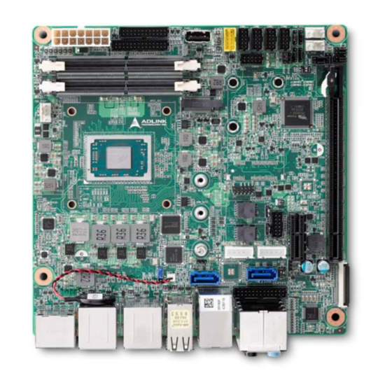
3.2. Component-Side Connectors Figure 4: AmITX-RZ-G Component-Side Connectors Item Description Item Description ATX Power Connector USB 2.0 Header 2x SODIMM DDR4 Sockets 5x Serial Port Headers PCIe x16 slot 1x CPU Fan Connector PCIe x1 slot 2x SYS Fan Connector USB 2.0 Type A Connector... -
Page 17: Mechanical Dimensions
AmITX-RZ-G 3.3. Mechanical Dimensions Top View Side View Dimensions: mm Figure 5: AmITX-RZ-G Mechanical Dimensions Mechanical Layout... -
Page 18: Thermal Solutions
3.4. Thermal Solutions AMD APU Cooler, H=35mm, 35W Standard Temp.: 0°C to 60°C P/N: 32-20583-1010 AMD APU Cooler, H=64.4mm, 54W Standard Temp.: 0°C to 60°C P/N: 32-20809-0000-A0 Mechanical Layout... -
Page 19: Connectors And Jumpers
AmITX-RZ-G 4. Connectors and Jumpers See 3.1 Rear I/O Connectors. 4.1. Rear IO Connectors 4.1.1. DisplayPort Connectors Three DisplayPort ports up to 4096 x 2160 @24Hz Pin # Signal Pin # Signal CN_DP0_P Ground CN_DP0_N CN_DP1_P Ground CN_DP1_N CN_DP2_P Ground... - Page 20 4.1.3. Ethernet Connectors (LAN1, LAN2) Dual 10/100/1000Mbit/s Ethernet ports based on 2x Intel® i211AT, supporting PXE and WOL over both LANs. Pin # 10BASE- 1000BASE-T T/100BASE-TX LAN_MDI0+ LAN_MDI0- LAN_MDI1+ LAN_MDI2+ LAN_MDI2- LAN_MDI1- LAN_MDI3+ LAN_MDI3- LED Behavior Position Function Color LED State NIC State LED1 Link Speed...
-
Page 21: Internal Connectors
Internal Connectors See 3.2 Component-Side Connectors on page 10. 4.2.1. ATX Power Connector (ATXPWR1s, proprietary) AmITX-RZ-G supports a proprietary internal ATX Power Connector (ATX_PWR). An adapter cable is provided for conection to a standard ATX power supply. Pin # Signal... - Page 22 4.2.2. SATA Connectors (SATA1/2) Two SATA 6 Gbps ports are available on the board (supports locking cable or locking SATA DOM). Note: Pin 7 on SATA1/2 can deliver power (None/3.3V/5V), Default is None. See 4.3.8 SATA1/2 Power Selection (SATA_PSEL1/2) on 27 for jumper settings. Pin # Signal GND/PWR...
- Page 23 AmITX-RZ-G 4.2.4. USB Header (USB910) 5V/SB5V: 5V supplies for external devices. SB5V is supplied during power down to allow wakeup on USB device activity during S3~S4 state. Pin # Signal Pin # Signal P5V_USB P5V_USB P9_DN_R- P10_DN_R P9_DP_R P10_DP_R USB Cable (optional): USB 2.0 Header to 2x Female Type-A Cable (length 200mm), P/N: 30-20874-1000...
- Page 24 4.2.5. Internal Audio Connector (FP_AUDIO1) 2x13-pin 2.0 pitch standard wafer connector Note: Signals shared with Audio Connector on Rear I/O Signal Pin # Pin # Signal LFE-OUT CEN-OUT AAGND AAGND FRONT-OUT-L FRONT-OUT-R AAGND AAGND REAR-OUT-L REAR-OUT-R SIDE-OUT-L SIDE-OUT-R AAGND AAGND MIC1-L MIC1-R AAGND...
- Page 25 AmITX-RZ-G 4.2.7. Serial COM Port Connectors (COM1-6) Serial Port Functions COM1 Supports RS-232 / RS-422 / RS-485, 5V/12V power support by jumper select (JPS3P, default NC). SWS1M: Switch for mode selection of COM1 (default RS-232). COM2-4 Support only RS-232 COM5-6...
- Page 26 RS-232/ccTALK (COM5-6 only) Pin # Signal Pin # Signal RS232_RX5_CCTalk 2 COM5_RTS# RS232_TX5_CCTalk COM5_CTS# RS232_RX6_CCTalk 8 COM6_RTS# RS232_TX6_CCTalk COM6_CTS# Note: See 4.3.5 COM5/6 Mode Selection Switch (SCN1/3) on 26 COM Cable (optional): COM Port Cable (length 250mm), P/N: 30-20876-0000 Connectors and Jumpers...
- Page 27 AmITX-RZ-G 4.2.8. Front Panel Connector (F_PANEL1) 2x12-pin 2.0 pitch standard wafer connector The front panel connector provides Audio Mic-In / Line Out, ATX power switch, Reset, HDD LED, and SUS LED (System Power LED). Pin # Signal IOH/IOL Type Note Pin # Signal...
- Page 28 4.2.9. Feature Connector (FC1) 2x14-pin 2.0 pitch standard wafer connector The feature connector provides Case Open, I2C, SMBus, and GPIO (10pin). Signal Description TEMPS Analogue temp sensor, connect to analog input of BMC EXT_BAT Connect to RTC power CASE_OPEN# Any time case open occurs, system will notice/show case open alert in POST during the next boot.
- Page 29 AmITX-RZ-G 4.2.10. SPI Header (SPI3) 2x6-pin 2.0 pitch standard wafer connector Type Signal Pin # Pin # Signal Type SB3V3 CS0# ADDIN CS1# MOSI ISOLATE MISO SPI_IO2_#WP 11 SPI_IO3_#HOLD IO Signal Description Serial Clock SB3V3 3.3V Standby Voltage power line. Normally output power, but when Motherboard is turned off then the on-board SPI Flash can be 3.3V power sourced via this pin.
- Page 30 4.2.11. DB40 Debug Board Connector FPC Connector Type: FCI 59GF Flex 10042867 Interface Signal Remark Interface Signal Remark VCC_SPI_IN SPI Power Input from TXD6 flash tool to module. Program Program HW need add MOS interface interface FET to switch SPI (continued) power for SPI ROM RXD6...
-
Page 31: Jumper And Switch Settings
COM5 mode jumper (SCN1/2) COM6 mode jumper (SCN3/4) PS_ON select (JPSON2) COM4 power sel COM3 power sel (JCOMPWR4) ATX/AT mode (JCOMPWR3) (JPSON1) COM2 power sel COM1 power sel (JCOMPWR2) (JCOMPWR1) Figure 6: AmITX-RZ-G Jumper and Switch Locations Connectors and Jumpers... - Page 32 4.3.1. ATX/AT Mode Jumper Selection (JPSON1) JPSON1 ATX/AT Mode 1-2 shorted ATX (default) 2-3 shorted 4.3.2. Clear CMOS (JCMOS1) JCMOS1 Clear CMOS 1-2 shorted Normal (default) 2-3 shorted Clear CMOS 4.3.3. COM1 Mode Selection Switch (JSETCOM1) RS-232 (default) RS-422 RS-485 4.3.4.
- Page 33 AmITX-RZ-G 4.3.6. BIOS Switch Setting (SW1) Switch Boot from SPI0 Boot from SPI1 (default) Failsafe BIOS Mode Normal BIOS Mode (default) Default: 1 ON and 2 OFF (Boot from on board BIOS and enable failsafe) 4.3.7. BIOS Write protect Selection (SPI5, SPI6)
-
Page 34: Onboard Connector Information
4.4. Onboard Connector Information Table 2: AmITX-RZ-G Onboard Connector Information Onboard Connector Mating Connector Connector Manufacturer Part No. Manufacturer Part No. ADLINK Cable COM Port COM1-6 23N6850-10S10B-01G- YOUNG YAK YY-1970H-2*5P 30-20876- B-01 (PH2.0) 0000 (optional) ATX power ATX_PW Molex 39-28-1143 E.C.I... -
Page 35: Driver Installation
AmITX-RZ-G 5. Driver Installation Drivers can be downloaded through the following link. https://www.adlinktech.com/Products/Industrial_Motherboards_SBCs/Mini-ITXEmbeddedBoards/AmITX-RZ- G?lang=en Driver Installation... - Page 36 This page intentionally left blank. Driver Installation...
-
Page 37: Smart Embedded Management Agent (Sema)
AmITX-RZ-G 6. Smart Embedded Management Agent (SEMA) The onboard microcontroller (BMC) implements power sequencing and Smart Embedded Management Agent (SEMA) functionality. The microcontroller communicates via the System Management Bus with the CPU/chipset. The following functions are implemented. • Total operating hours counter. Counts the number of hours the module has been run in minutes. -
Page 38: Table 4: Sema Bmc Status
6.1.2. Main Current The BMC implements a current monitor. The current can be read by calling the SEMA function “Get Main Current”. The function returns four 16-bit values divided in high-byte (MSB) and low-byte (LSB). These 4 values represent the last 4 currents drawn by the board. The values are sampled every 250ms. The order of the 4 values is NOT in chronological order. -
Page 39: Table 5: Sema Exception Codes
AmITX-RZ-G 6.1.4. Exception Codes In case of an error, the BMC drives a blinking code on the blue Status LED (LED1). The same error code is also reported by the BMC Flags register. The Exception Code is not stored in the Flash Storage and is cleared when the power is removed. - Page 40 This page intentionally left blank. Smart Embedded Management Agent (SEMA)
-
Page 41: System Resources
AmITX-RZ-G 7. System Resources 7.1. System Memory Map Table 7: System Memory Map Address Range (decimal) Address Range (hex) Size Description (4GB - 2MB) FFE00000 - FFFFFFFF 2 MB High BIOS Area (4GB - 18MB) FEE00000 - FEEFFFFF 1 MB... -
Page 42: Interrupt Request (Irq) Lines
7.3. Interrupt Request (IRQ) Lines 7.3.1. IRQ Lines PIC Mode Table 9: IRQ Lines PIC Mode IRQ# Typical Interrupt Resource Connected to Pin Available Counter 0 Keyboard Controller Cascade Interrupt Serial Port 2 (COM2) IRQ3 via SERIRQ/PIRQ Note (1) Serial Port 1 (COM1) IRQ4 via SERIRQ/PIRQ Note (1) Generic... -
Page 43: Table 10: Irq Lines Apic Mode
AmITX-RZ-G 7.3.2. IRQ Lines APIC Mode Table 10: IRQ Lines APIC Mode IRQ# Typical Interrupt Resource Connected to Pin Available Counter 0 Keyboard Controller Cascade Interrupt Serial Port 2 (COM2) IRQ3 via SERIRQ/PIRQ Serial Port 1 (COM1) IRQ4 via SERIRQ/PIRQ... -
Page 44: Pci Configuration Space Map
7.4. PCI Configuration Space Map Table 11: PCI Configuration Space Map Device Function Routing Description Number Number Number Host Bridge IOMMU PCIe Dummy Host Bridge Internal PCIe Bridge 2 PCIe Dummy Host Bridge Internal PCIe GPP Bridge 1 Internal PCIe GPP Bridge 2 Internal SMBus Controller Internal... -
Page 45: Pci Interrupt Routing Map
AmITX-RZ-G 7.5. PCI Interrupt Routing Map Table 12: PCI Interrupt Routing Map PCIe PCIe GPP PCIe GPP SMBus ATI VGA ATI HD LPC Bridge Intel LAN Bridge 2 Bridge 1 Bridge 2 Controller Controller Audio Line Int0 INTE: 28 INTE: 52... - Page 46 This page intentionally left blank. System Resources...
-
Page 47: Bios Setup
AmITX-RZ-G 8. BIOS Setup 8.1. Menu Structure This section presents the six primary menus of the BIOS Setup Utility. Use the following table as a quick reference for the contents of the BIOS Setup Utility. The subsections in this section describe the submenus and setting options for each menu item. -
Page 48: Main
8.2. Main The Main Menu provides read-only information about your system and also allows you to set the System Date and Time. Refer to the tables below for details of the submenus and settings. 8.2.1. Main > BIOS Information Feature Options Description Info only... - Page 49 AmITX-RZ-G Feature Options Description Current Runtime Info Only The returned value specifies the time in seconds the system is running in S0 state. This counter is cleared when the system is removed from the external power supply. Power Cycles Info Only...
-
Page 50: Advanced
8.3. Advanced This menu contains the settings for most of the user interfaces in the system. 8.3.1. Advanced > CPU Configuration Feature Options Description CPU Configuration Info only CPU Brand String Info only Display CPU brand string Processor Family Info only Display CPU family Processor Model Info only... - Page 51 AmITX-RZ-G Feature Options Description ACPI Sleep State Suspend Disabled Select the highest ACPI sleep state the system will enter when the SUSPEND button is pressed. S3 (Suspend to RAM) Lock Legacy Resources Enables or Disables Lock of Legacy Resources Disabled...
- Page 52 8.3.3. Advanced > System Management Feature Options Description System Management Info only Version: Info only SEMA Firmware Info only Display SEMA firmware Build Date Info only Display SEMA firmware build date SEMA Bootloader Info only Display SEMA boot loader Build Date Info only Display SEMA boot loader build date SEMA Features ►...
- Page 53 AmITX-RZ-G 8.3.4. Advanced > Thermal Management Feature Options Description Temperatures and Fan Speed Info only Info only CPU Temperature Current Info only Display current CPU temperature Startup Info only Display CPU startup temperature Info only Display CPU min. temperature Info only Display CPU max.
- Page 54 Feature Options Description Trigger Temperature Trigger Temperature PWM Level PWM Level Trigger Point 2 Info only Trigger Temperature Trigger Temperature PWM Level PWM Level Trigger Point 3 Info only Trigger Temperature Trigger Temperature PWM Level PWM Level Trigger Point 4 Info only Trigger Temperature Trigger Temperature...
- Page 55 AmITX-RZ-G Feature Options Description PWM Level PWM Level Trigger Point 2 Info only Trigger Temperature Trigger Temperature PWM Level PWM Level Trigger Point 3 Info only Trigger Temperature Trigger Temperature PWM Level PWM Level Trigger Point 4 Info only Trigger Temperature...
- Page 56 8.3.8. Advanced > Super IO Configuration Feature Options Description Serial Port 1 Configuration ► Submenu Set Parameters of Serial Port 1 (COM1). Serial Port 2 Configuration ► Submenu Set Parameters of Serial Port 2 (COM2). Serial Port 3 Configuration ► Submenu Set Parameters of Serial Port 3 (COM3).
- Page 57 AmITX-RZ-G 8.3.9. Advanced > Serial Console Redirection Feature Options Description Serial Console Redirection Info only COM1 Info only Console Redirection Console Redirection Enable or Disable. Disabled Enabled Console Redirection Settings ► Submenu The settings specify how the host computer and the remote computer (which the user is using) will exchange data.
- Page 58 Feature Options Description setting is 1 stop bit. Communication with slow devices may require more than 1 stop bit. Flow Control Flow control can prevent data loss from buffer None overflow. When sending data, if the receiving buffers Hardware RTS/CTS are full, a 'stop' signal can be sent to stop the data flow.
- Page 59 AmITX-RZ-G Feature Options Description Bits per second 9600 Selects serial port transmission speed. The speed 19200 must be matched on the other side. Long or noisy 57600 lines may require lower speeds. 115200 Flow control can prevent data loss from buffer overflow.
- Page 60 Feature Options Description 1 sec 5 sec The time-out value for Control, Bulk, and Interrupt USB transfer time-out transfers. 10 sec 20 sec 10 sec USB mass storage device Start Unit command time- 20 sec Device reset time-out out. 30 sec 40 sec Maximum time the device will take before it properly reports itself to the Host Controller.
- Page 61 AmITX-RZ-G Feature Options Description Schedule an Operation for the Security Device. None Pending operation NOTE: Your Computer will reboot during restart in TPM Clear order to change State of Security Device. Enabled Platform Hierarchy Enable or Disable Platform Hierarchy Disabled...
- Page 62 8.3.15. Advanced > AMD CBS Feature Options Description AMD CBS Info only Zen Common Options ► Submenu Zen Common Options NBIO Common Options ► Submenu NBIO Common Options 8.3.15.1. Advanced > AMD CBS > Zen Common Options Feature Options Description Zen Common Options Info only Auto...
- Page 63 AmITX-RZ-G 8.3.15.4. Advanced > AMD CBS > NBIO Common Options Feature Options Description NBIO Common Options Info only GFX Configuration ► Submenu GFX Configuration NB Configuration ► Submenu NB Configuration PCIe Configuration ► Submenu PCIe Configuration 8.3.15.5. Advanced > AMD CBS > NBIO Common Options > GFX Configuration...
-
Page 64: Security
8.4. Security 8.4.1. Security > Password Description Feature Options Description Administrator Password Enter password User Password Enter password Secure Boot menu ► Submenu Customizable Secure Boot settings 8.4.2. Security > Secure Boot menu Feature Options Description Secure Boot Info only System Mode Info only Secure Boot... - Page 65 AmITX-RZ-G Feature Options Description Network Disabled Boot Option #2 Hard Disk CD/DVD USB Hard Disk USB CD/DVD Sets the system boot order USB Key USB Floppy USB Lan Network Disabled Boot Option #3 Hard Disk CD/DVD USB Hard Disk USB CD/DVD...
- Page 66 Feature Options Description Boot Option #7 Hard Disk CD/DVD USB Hard Disk USB CD/DVD Sets the system boot order USB Key USB Floppy USB Lan Network Disabled Boot Option #8 Hard Disk CD/DVD USB Hard Disk USB CD/DVD Sets the system boot order USB Key USB Floppy USB Lan...
-
Page 67: Save & Exit
AmITX-RZ-G 8.6. Save & Exit Feature Options Description Save Changes and Exit Yes No Exit system setup after saving the changes. Discard Changes and Exit Yes No Exit system setup without saving any changes. Save Changes and Reset Yes No Reset the system after saving the changes. -
Page 68: Safety Instructions
Safety Instructions Read and follow all instructions marked on the product and in the documentation before you operate your system. Retain all safety and operating instructions for future use. • Please read these safety instructions carefully. • Please keep this User‘s Manual for later reference. •... -
Page 69: Getting Service
5215 Hellyer Avenue, #110, San Jose, CA 95138, USA Tel: +1-408-360-0200 Toll Free: +1-800-966-5200 (USA only) Fax: +1-408-360-0222 Email: info@adlinktech.com ADLINK Technology (China) Co., Ltd. Address: 300 Fang Chun Rd., Zhangjiang Hi-Tech Park, Pudong New Area Shanghai, 201203 China Tel: +86-21-5132-8988 Fax: +86-21-5132-3588 Email: market@adlinktech.com...
Need help?
Do you have a question about the AmITX-RZ-G and is the answer not in the manual?
Questions and answers