
Subscribe to Our Youtube Channel
Related Manuals for ADLINK Technology AmITX-AL-I


Summary of Contents for ADLINK Technology AmITX-AL-I
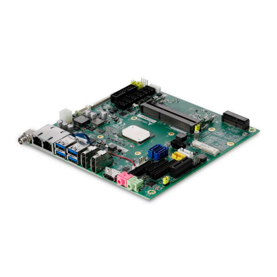
- Page 1 AmITX-AL-I User’s Manual Thin Mini-ITX Embedded Motherboard with Intel® Atom™, Pentium®, and Celeron® SoCs Manual Rev.: Revision Date: October 17, 2018 Part Number: 50-1J087-1000...
- Page 2 Preface Copyright Copyright 2018 ADLINK Technology, Inc. This document contains proprietary information protected by copyright. All rights are reserved. No part of this manual may be reproduced by any mechanical, electronic, or other means in any form without prior written permission of the manufacturer.
-
Page 3: Table Of Contents
AmITX-AL-I Table of Contents Preface ..........................ii List of Figures ........................v List of Tables ........................vi Introduction ........................ 1 1.1. Packing List ........................2 1.2. Optional Accessories ..................... 2 Specifications ......................3 2.1. Core System ......................... 3 2.2. Rear I/O Connectors ..................... 3 2.3. -
Page 4: Preface
7.1. Menu Structure ......................45 7.2. Main ..........................46 7.3. Advanced ........................48 7.4. Chipset ........................59 7.5. Security ........................66 7.6. Boot ..........................67 7.7. Save & Exit ......................... 67 Safety Instructions ......................69 Getting Service ......................... 70 Preface... -
Page 5: List Of Figures
AmITX-AL-I List of Figures Figure 1: AmITX-AL-I Functional Block Diagram ..................9 Figure 2: AmITX-AL-I Rear I/O .......................11 Figure 3: AmITX-AL-I Component Side Connectors ................11 Figure 4: AmITX-AL-I Solder Side Connectors ..................12 Figure 5: AmITX-AL-I Mechanical Dimensions ..................13 Preface... - Page 6 List of Tables Table 1: AmITX-AL-I Processors ......................1 Table 2: AmITX-AL-I Onboard Connector Information ................33 Table 3: SEMA Onboard Voltage Monitor ....................35 Table 4: SEMA BMC Status ........................36 Table 5: SEMA Exception Codes ......................36 Table 6: SEMA BMC Flags........................37 Table 7: System Memory Map .......................39...
-
Page 7: Introduction
Mini PCIe slot, mSATA slot, and 2x SATA 6 Gb/s ports. A feature connector provides 10 GPIOs, SMBus, and I C, and optional SIM card slot and microSD card slot are available. The AmITX-AL-I is equipped with SPI AMI EFI BIOS, supporting embedded features such as hardware monitor and watchdog timer. -
Page 8: Packing List
1.1. Packing List • AmITX-AL-I Thin Mini-ITX Embedded Board • SATA dual power cable (P/N: 30-20875-0000) • SATA cable (P/N: 30-10057-0600) • Standard rear I/O shield (PN:34-25318-2000) 1.2. Optional Accessories • COM port cable, 1 port (P/N: 30-20876-0000) • PS/2 KB/MS cable (P/N: 30-20873-0000) •... -
Page 9: Specifications
AmITX-AL-I 2. Specifications 2.1. Core System Dual or quad-core Intel® Atom™, Pentium®, and Celeron® Processor SoC AtomTM x7-E3950 1.60/2.00 (Burst) GHz 12W (4C/1866) AtomTM x5-E3940 1.60/1.80 (Burst) GHz 9.5W (4C/1866) AtomTM x5-E3930 1.30/1.80 (Burst) GHz 6.5W (2C/1866) Pentium® N4200 1.10/2.50 (Burst) GHz 6W (4W SDP) (4C/1866) Celeron®... -
Page 10: Internal Headers And Connectors
2.3. Internal Headers and Connectors PCI Express Slots 1x PCIe x1 slot 2x Mini PCIe slots: one PCIe + USB; one mSATA (colay with SATA1) 2x USB 2.0 via onboard header, 1x USB 2.0 via front panel connector SATA 2x SATA 6Gb/s (SATA1, SATA2) SATA Power Connector Serial 2x RS-232/422/485 headers with 0V/5V/12V power, 4x RS-232 headers... -
Page 11: Video
AmITX-AL-I 2.7. Video GPU Feature Support Intel® 9th generation LP graphics core architecture with up to 18 execution units supporting three independent displays • 3D graphics hardware acceleration • Support for DirectX12/11.3/10/9.3, OCL 2.0, OGL ES 3.0, OGL 4.3 •... - Page 12 2.10.1. Power Consumption Processor Intel® Atom™ E3950 @ Intel® Atom ™ E3940 @ Intel® Atom ™ E3930 @ 1.60Ghz (4C 1.6GHz, 2x 1.60GHz (4C 1.6GHz, 2x 1MB 1.30GHz (4C 1.6GHz, 2x 1MB 1MB LK2) LK2) LK2) Memory Transcend Transcend TS512MSK64W6H Transcend TS512MSK64W6H TS512MSK64W6H 4GB 4GB DDR3 SO-DIMM PC3-...
- Page 13 AmITX-AL-I Processor Intel® Atom™ E3950 @ Intel® Atom ™ E3940 @ Intel® Atom ™ E3930 @ 1.60Ghz (4C 1.6GHz, 2x 1.60GHz (4C 1.6GHz, 2x 1MB 1.30GHz (4C 1.6GHz, 2x 1MB 1MB LK2) LK2) LK2) 5VSB(A) Power 14.4 12.84 consumption(W) Windows MAX mode/Enable EIST 3.3V(A)
-
Page 14: Temperatures
Processor Intel® Atom™ E3950 @ Intel® Atom ™ E3940 @ Intel® Atom ™ E3930 @ 1.60Ghz (4C 1.6GHz, 2x 1.60GHz (4C 1.6GHz, 2x 1MB 1.30GHz (4C 1.6GHz, 2x 1MB 1MB LK2) LK2) LK2) 12V(A) 0.05 0.05 0.05 Power consumption(W) S5 Mode with ECO Enable 3.3V(A) 5V(A) 12V(A) -
Page 15: Functional Block Diagram
SEMA CPU FAN Super I/O COM3 SMBus SYS FAN COM4 TM4C123 x RS-232 COM5 (optional) COM6 Sensor PS/2 PS/2 KB/MS LM73 GPIO Feature Connector PCA9535 GPIO (optional) System Signals Rear I/O Internal I/O Figure 1: AmITX-AL-I Functional Block Diagram Specifications... - Page 16 This page intentionally left blank. Specifications...
-
Page 17: Mechanical Layout
Front Panel ATX Power PCIe x1 SPI Socket Audio Front Panel Auxiliary LVDS SATA Power 6x RS-232 mSATA Slot TPM Header 2x SATA 3 PS/2 KB/MS 2 Stacked SODIMM System Fan Mini PCIe Figure 3: AmITX-AL-I Component Side Connectors Mechanical Layout... -
Page 18: Figure 4: Amitx-Al-I Solder Side Connectors
3.1.3. Solder Side Connectors microSD Card Slot DB40 Connector SIM Card Slot Figure 4: AmITX-AL-I Solder Side Connectors Mechanical Layout... -
Page 19: Mechanical Dimensions
AmITX-AL-I 3.2. Mechanical Dimensions 160.02 154.94 152.75 140.90 130.92 118.77 105.37 95.91 Top View (W/O RTC battery) 44.91 22.86 10.16 Side View (W/O RTC battery) Dimensions: mm Figure 5: AmITX-AL-I Mechanical Dimensions Mechanical Layout... - Page 20 This page intentionally left blank. Mechanical Layout...
-
Page 21: Connectors And Jumpers
4.1.1. DC Power Inlet The AmITX-AL-I supports a screw-type external 12V DC-in power connector. Maximum current draw is 10A. Note: Either the DC Power Inlet or the internal ATX Power Connector (ATX_PWR) must be used to supply the motherboard with +12V ±5%. - Page 22 4.1.2. DisplayPort DisplayPort v1.2 specification ports up to 4096x2160 @ 24Hz (2x DisplayPort by build option, in place of HDMI) Pin # Signal Pin # Signal CN_DP0_P Ground CN_DP0_N CN_DP1_P Ground CN_DP1_N CN_DP2_P Ground CN_DP2_N CN_DP3_P Ground CN_DP3_N DDC_AUX_SEL 14 CN_CEC CN_AUX_P Ground...
- Page 23 AmITX-AL-I 4.1.4. Ethernet Connectors (LAN1, LAN2) Intel® i211AT (MAC/PHY) Ethernet controller (Intel® i210 is build option for extreme temperature operating range support) Pin # 10BASE- 1000BASE-T T/100BASE-TX LAN_MDI0+ LAN_MDI0- LAN_MDI1+ LAN_MDI1- LAN_MDI2+ LAN_MDI2- LAN_MDI3+ LAN_MDI3- LED1 (Speed) LED2 (Link/Activity) Status...
-
Page 24: Internal Connectors
Internal Connectors 4.2.1. ATX Power Connector 4-pin (ATX_PWR1) AmITX-AL-I supports a proprietary internal ATX Power Connector (4-pin). Note: Either the DC Power Inlet or the internal ATX Power Connector (4-pin) must be used to supply the motherboard with +12V ±5%. - Page 25 AmITX-AL-I 4.2.2. SATA Connectors (SATA1, SATA2, CN22-23) Two SATA ports are available on the AmITX-AL-I and support SATA Gen3 (6.0/3.0/1.5Gb/s). Note: If mSATA is installed, SATA1 is disabled. See 4.3.3 SATA1/mSATA Select (JP11). Pin # Signal 4.2.3. SATA Power Connector (ST_PWR, CN24)
- Page 26 4.2.4. USB 2.0 Header (CN17) 5V/SB5V: 5V is supplied for external devices. SB5V is supplied during power down to allow wakeup on USB device activity during S3~S4 state. Pin # Signal Pin # Signal P5V_USB2_4 P5V_USB2_5 USB2_HUB4_N USB2_HUB5_N USB2_HUB4_P USB2_HUB5_P USB Cable (optional): USB 2.0 Header to 2x Female Type-A Cable (length 200mm), P/N: 30-20874-1000 4.2.5.
- Page 27 AmITX-AL-I 4.2.6. Internal Audio Connector (CN16) 2x16-pin 2.0 pitch standard wafer connector. Note: Signals shared with Audio Connector on Rear I/O. Signal Pin # Pin # Signal LFE_R CEN_L AGND_AU AGND_AU LOUT_L_CN LOUT_R_CN AGND_AU AGND_AU CN16 LFE_R CEN_L JACK-G JACK-G...
- Page 28 4.2.8. Serial COM Port Connectors (CN29-CN34) Four internal Serial Ports (COM1-6) Serial Port Functions COM1 Supports RS-232/422/485, 0V5V/12V power support by jumper selection SWS1M: Switch for mode selection of COM1 (default RS-232). COM2 Supports RS-232/422/485, 0V/5V/12V power support by jumper selection SWS2M: Switch for mode selection of COM2 (default RS-232).
- Page 29 AmITX-AL-I RS-485 (COM1-2 only) Pin # Signal Pin # Signal Tx/Rx- Tx/Rx+ — — — — — RS-232/422/485 Selection (COM1-2 only) SWS1M/SWS2M (RS-232/422/485 Mode Select) RS-232 RS-422 RS-485 (default) COM1 Power Selection (JP7, JP8) JP7 COM1 PWR +12V P_+5V_S0_COM P_+12V_S_COM...
- Page 30 COM Cable (optional): COM Port Cable (length 250mm), P/N: 30-20876-0000 4.2.9. LVDS Connector (CN13) FFC Connector: Female, 30pin, 1mm pitch. (JAE, FI-X30SSLA-HF) Supports non-EDID type LCD panels. Signal Description LVDS LVDS A Channel data A0..A3 LVDS ACLK LVDS A Channel clock LVDS LVDS B Channel data B0..B3...
- Page 31 AmITX-AL-I Note Type Signal Pin # Pin # Signal Type Note LVDS LVDS B0+ PANEL POWER PWR Max 0.5A Max. 0.5A PWR POWER GND 15 PANEL POWER PWR Max 0.5A LVDS LVDS B1- POWER GND Max. 0.5A 4.2.10. LVDS Auxiliary Connector (CN14) Wafer 1x10 pin: 1.25 mm pitch (MOLEX, 53261-1071)
- Page 32 4.2.11. Front Panel Header (CN27) 2x12-pin 2.0 pitch standard wafer header The front panel header provides USB2.0, Audio MIC-In / Line-Out, ATX power switch, Reset, HDD LED, and SUS LED (System Power LED). Pin # Signal Ioh/ Iol Type Note Pin # Signal Type Ioh/ Iol Note USB7_5V USB7_5V...
- Page 33 SB3V3 PU 330ohm SUS_LED 4.2.13. Feature Connector (CN28) 2x14-pin 2.0 pitch standard wafer connector The feature connector of AmITX-AL-I provides Case Open, I2C, SMBus, and GPIO (10pin). Signal Description TEMPS Analogue temp sensor, connect to analog input of BMC EXT_BAT...
- Page 34 4.2.14. SPI Header (CN40) 2x6-pin 2.0 pitch standard wafer connector Type Signal Pin # Pin # Signal Type SB3V3 CS0# ADDIN CS1# MOSI ISOLATE MISO SPI_IO2_#WP 11 SPI_IO3_#HOLD IO Signal Description Serial Clock SB3V3 3.3V Standby Voltage power line. Normally output power, but when Motherboard is turned off then the on-board SPI Flash can be 3.3V power sourced via this pin.
- Page 35 AmITX-AL-I 4.2.15. DB40 Debug Board Connector FPC Connector Type: FCI 59GF Flex 10042867 Pin Interface Signal Remark Pin Interface Signal Remark VCC_SPI_IN SPI Power Input from TXD6 Program flash tool to module. HW Program interface need add MOS FET to...
-
Page 36: Jumper And Switch Settings
4.3. Jumper and Switch Settings RS-232/422/485 Clear Select (SWS1M, CMOS SWS2M) (JP6) ATX/AT Mode Select (JP1) COM Power (JP7-JP10) SATA1/m SATA LVDS Backlight Select Power Select (JP11) (JP2) Load BIOS Default LVDS Backlight (SW2) Enable (JP4) BIOS Config LVDS Panel (BSW1) Power Select (JP3, JP5) - Page 37 AmITX-AL-I 4.3.3. SATA1/mSATA Selection (JP11) SATA1/mSATA Select SATA2 (default) mSATA 4.3.4. LVDS Backlight Power Selection (JP2) Backlight Power 5V (default) 4.3.5. LVDS Panel Power Selection (JP3, JP5) JP3/JP5 Panel Power 3.3V (default) Panel Power control: JP3 & JP5 Jumper settings Set the LVDS panel as +3.3V...
- Page 38 4.3.7. Serial Port Mode Switch Setting (SWS1M, SWS2M) RS-232/422/485 Selection (COM1-2 only) SWS1M (SER1 MODE SEL) RS-232 (default) RS-422 RS-485 SWS2M (SER2 MODE SEL) RS-232 (default) RS-422 RS-485 4.3.8. Serial Port Power Selection (JP7, JP8, JP9, JP10) COM1 Power selection (JP7, JP8) JP7 COM1 PWR +12V P_+5V_S0_COM P_+12V_S_COM...
-
Page 39: Onboard Connector Information
Boot from SPI1 (Pos. 1-4) (default) BIOS MODE Normal BIOS Failsafe BIOS (Pos. 2-3) (default) 4.4. Onboard Connector Information Table 2: AmITX-AL-I Onboard Connector Information Connector Onboard Connector Mating Connector ADLINK Cable Manufacturer Part No. Manufacturer Part No. COM Port CN29-... - Page 40 This page intentionally left blank. Connectors and Jumpers...
-
Page 41: Smart Embedded Management Agent (Sema)
AmITX-AL-I 5. Smart Embedded Management Agent (SEMA) The onboard microcontroller (BMC) implements power sequencing and Smart Embedded Management Agent (SEMA) functionality. The microcontroller communicates via the System Management Bus with the CPU/chipset. The following functions are implemented. • Total operating hours counter. Counts the number of hours the module has been run in minutes. -
Page 42: Table 4: Sema Bmc Status
ADC Channel Voltage Name Voltage Formula [V] 3.3VSB (MSB<<8 + LSB) x 1.100 x 3.3 / 1024 (MSB<<8 + LSB) x 3.3 / 1024 Main Current 5.1.2. Main Current The BMC of the AmITX-AL implements a current monitor. The current can be read by calling the SEMA function “Get Main Current”. -
Page 43: Table 6: Sema Bmc Flags
AmITX-AL-I Exception Code Error Message Description NO_CB_PWRGD No signal for CB Power Good CRITICAL_TEMP Critical temperature violation POWER_FAIL Power failure VOLTAGE_FAIL Voltage failure NO_3V3_5V_A_PG No signal for 3V3_5V_A Power Good NO_VNN_PG No signal for VNN Power Good NO_1V24_A_PG No signal for 1V24_A Power Good... - Page 44 This page intentionally left blank. Smart Embedded Management Agent (SEMA)
-
Page 45: System Resources
AmITX-AL-I 6. System Resources 6.1. System Memory Map Table 7: System Memory Map Address Range (decimal) Address Range (hex) Size Description (4GB-2MB) FFE00000 – FFFFFFFF 2 MB High BIOS Area (4GB-18MB) – (4GB-17MB-1) FEE00000 – FEEFFFFF 1 MB MSI Interrupts (4GB-20MB) –... -
Page 46: Interrupt Request (Irq) Lines
Hex Range Device 0500~0A2F Motherboard Resource CF8-CFB PCI configuration address register (32 bit I/O only) Reset Control register (8 bit I/O) CFC-CFF PCI configuration data register D00-FFFF PCI Express Root Complex 164E-164F MotherBoard Resource D000-EFFF PCIE Root Port F000-F03F F040-F05F SMBus controller F060-F097 SATA controller... -
Page 47: Table 10: Irq Lines Apic Mode
AmITX-AL-I 6.3.2. IRQ Lines APIC Mode Table 10: IRQ Lines APIC Mode IRQ# Typical Interrupt Resource Connected to Pin Available Counter 0 Keyboard controller Cascade interrupt from slave PIC Serial Port 2 (COM2) IRQ3 via SERIRQ / PIRQ Note (1) -
Page 48: Pci Configuration Space Map
6.4. PCI Configuration Space Map Table 11: PCI Configuration Space Map Device Function Routing Description Number Number Number Intel Host Bridge Internal Intel VGA Controller Internal Intel HD Audio Device Internal Intel Corporation Communication Device Internal Intel SATA Controller Internal Intel PCIE Root Port 1 Internal Intel PCIE Root Port 2... -
Page 49: Pci Interrupt Routing Map
AmITX-AL-I 6.5. PCI Interrupt Routing Map Table 12: PCI Interrupt Routing Map Audio xHCI PCIE Port 3 PCIE Port 4 PCIE Port 5 Line Controller Controller Controller #1 Int0 INTA:25 INTA:None INTA:None INTA:22 INTA:23 INTA:20 Int1 INTB:23 INTB:20 INTB:21 Int2... - Page 50 This page intentionally left blank. System Resources...
-
Page 51: Bios Setup
AmITX-AL-I 7. BIOS Setup 7.1. Menu Structure This section presents the six primary menus of the BIOS Setup Utility. Use the following table as a quick reference for the contents of the BIOS Setup Utility. The subsections in this section describe the submenus and setting options for each menu item. -
Page 52: Main
7.2. Main The Main Menu provides read-only information about your system and also allows you to set the System Date and Time. Refer to the tables below the screen shot of this menu for details of the submenus and settings. 7.2.1. - Page 53 AmITX-AL-I 7.2.3.2. Board Information > Runtime Statistics Feature Options Description Runtime Statistics Info only Total Runtime Read only The returned value specifies the total time in minutes the system is running in S0 state. Current Runtime Read only The returned value specifies the time in seconds the system is running in S0 state.
-
Page 54: Advanced
7.3. Advanced This menu contains the settings for most of the user interfaces in the system. 7.3.1. CPU Configuration Feature Options Description CPU Configuration Info only Socket 0 CPU Information Submenu Display socket specific CPU Information Speed Info only Display CPU Speed Frequency 64-bit Info only Display CPU 64-bit supported... - Page 55 AmITX-AL-I Feature Options Description L1 Data Cache Info only Display L1 Data Cache L1 Code Cache Info only Display L1 Code Cache L2 Cache Info only Display L2 Cache L3 Cache Info only Display L3 Cache 7.3.1.2. CPU Configuration > CPU Power Management...
- Page 56 Feature Options Description Power Limit 1 power Auto Power Limit 1 in Watts. Auto will program Power Limit 1 based on silicon default support value. Power Limit 1 Time Window Auto Power Limit 1 Time Window value in Seconds. Auto will program Power Limit 1 Time Window based on silicon default support value.
- Page 57 AmITX-AL-I 7.3.2. Graphics Configuration Feature Options Description LVDS Info only Data format and Color Depth VESA 24 bpp Data format and Color Depth select JEIDA 24 bpp JEIDA/VESA 18 bpp LVDS Output Mode Single LVDS bus Single/Dual mode select Dual LVDS bus...
- Page 58 Feature Options Description VGFX Read only Display actual VGFX voltage VMEM Read only Display actual VMEM voltage 5VSB Read only Display actual 5VSB voltage VIN(12V) Read only Display actual VIN(12V) voltage Read only Display actual 5V voltage 3.3V Read only Display actual 3.3V voltage 3.3VSB Read only...
- Page 59 AmITX-AL-I Feature Options Description AT/ATX mode Info only ACPI Thermal Trigger Info only Power-Up to last state Info only Backlight restore Info only DTS register available Info only DTS offset registers programmable Info only TIVA BMC Info only PEC Control...
- Page 60 Feature Options Description Read only Display board Max. temperature CPU Fan Speed Read only Display CPU Fan RPM System Fan1 Speed Read only Display System Fan1 RPM 7.3.5.2. Thermal Management > Smart Fan Feature Options Description Smart Fan Info only CPU Smart Fan Temperature Source CPU Sensor CPU smart fan temperature source...
- Page 61 AmITX-AL-I 7.3.7. CSM Configuration Feature Options Description Compatibility Support Module Info only Configuration CSM Support Enabled Enable/Disable CSM Support Disabled CSM16 Module Version Read Only Display CSM16 Module Version GateA20 Active Upon Request UPON REQUEST - GA20 can be disabled using BIOS services.
- Page 62 7.3.8.1. Super IO > Serial Port 1 Configuration Feature Options Description Serial Port 1 Configuration Info only Serial Port Disabled Enable or Disable Serial Port (COM) Enabled Device Setting Info only Change Setting Auto Select an optimal setting for Super IO Device. IO=3F8;IRQ=4;...
- Page 63 AmITX-AL-I Feature Options Description Console Redirection Settings Submenu The settings specify how the host computer and the remote computer (which the user is using) will exchange data. Both computers should have the same or compatible settings. COM5 Info only Console Redirection Disabled Console Redirection enable or disable.
- Page 64 Feature Options Description Resolution 100x31 Disabled Enables or disables extended terminal resolution Enable Legacy OS Redirection 80x24 On legacy OSes, the number of rows and columns supported by redirection 80x25 Putty KeyPad VT100 Select Function Key and KeyPad on Putty. LINUX XTERMR6 ESCN...
-
Page 65: Chipset
AmITX-AL-I 7.3.12. Miscellaneous Feature Options Description Chassis Intrusion Support Disabled Chassis Intrusion Support. Enabled 7.3.13. Trusted Computing Feature Options Description Security Device Support Disabled Enables or Disables BIOS support for security device. O.S. will not show security Device. TCG EFI protocol... - Page 66 Feature Options Description PCIE VGA Workaround Disable Enable it if your PCIe card cannot boot to DOS. This is for Test only. Enable 7.4.2. South Bridge Feature Options Description Serial IRQ Mode Quiet Configure Serial IRQ Mode Continuous SMBus Support Disable Enable/Disable SMBus Support Enable...
- Page 67 AmITX-AL-I Feature Options Description LCD Panel Type Auto Select LFP panel used by Internal Graphics Device by selecting the appropriate setup item. 640x480 800x600 1024x768 1280x1024 1400x1050(RB) LVDS1 1400x1050 LVDS2 1600x1200 LVDS 1366x768 LVDS 1680x1050 1920x1200 1440x900 LVDS 1600x900 LVDS...
- Page 68 7.4.4. South Cluster Configuration Feature Options Description HD-Audio Configuration Submenu HD-Audio Configuration Settings PCI Express Configuration Submenu PCI Express Configuration Settings SATA Devices Submenu Press <Enter>.to select the SATA Device Configuration Setup options. SCC Configuration Submenu SCC Configuration Settings USB Configuration Submenu USB Configuration Settings Miscellaneous...
- Page 69 AmITX-AL-I 7.4.4.3. South Cluster Configuration > PCI Express Configuration > PCIe Express Root Port3 Feature Options Description PCIe Express Root Port3 Disabled Control the PCI Express Root Port. Enabled Auto: To disable unused root port automatically for the most optimum power savings.
- Page 70 Feature Options Description Extra Bus Reserved Extra Bus Reserved (0-7) for bridges behind this Root Bridge. Reserved Memory Reserved Memory and Prefetchable memory (1-20MB) Range for this Root Bridge. Reserved I/O Reserved I/O (4K/8K/12K/46K/20K) Range for this Root Bridge. PCH PCIE LTR Disabled PCH PCIE Latency Reporting Enable/Disable.
- Page 71 AmITX-AL-I Feature Options Description Port 0 Disabled Enable or Disable SATA Port. Enabled SATA Port 0 Hot Plug Capability Disabled If enabled, SATA port will be reported as Hit Plug capable. Enabled Configured as eSATA Info only Mechanical Preserve Switch...
-
Page 72: Security
7.4.4.7. South Cluster Configuration > Miscellaneous Feature Options Description High Precision Timer Disabled Enable or Disable the High Precision Event Timer Enabled State After G3 S0 State Specify what state to go to when power is re-applied after a power failure (G3 State). S5 State S0 State: System will boot directly as soon as power Last State... -
Page 73: Boot
AmITX-AL-I 7.6. Boot 7.6.1. Boot Configuration Feature Options Description Boot Configuration Info only Number of seconds to wait for setup activation key. Setup Prompt Timeout 65535 (0xFFFF ) means indefinite waiting. Bootup NumLock State Select the keyboard NumLock state. Quiet Boot Disabled Enable or Disable Quiet Boot option. - Page 74 7.7.2. Default Options Feature Options Description Restores Defaults Yes/No Restore/Load Default values for all the setup options. Save as User Default Yes/No Save the changes done so far as User Defaults. Restore User Defaults Yes/No Restore the User Defaults to all the setup options. 7.7.3.
-
Page 75: Safety Instructions
AmITX-AL-I Safety Instructions Read and follow all instructions marked on the product and in the documentation before you operate your system. Retain all safety and operating instructions for future use. • Please read these safety instructions carefully. • Please keep this User‘s Manual for later reference. -
Page 76: Getting Service
5215 Hellyer Avenue, #110, San Jose, CA 95138, USA Tel: +1-408-360-0200 Toll Free: +1-800-966-5200 (USA only) Fax: +1-408-360-0222 Email: info@adlinktech.com ADLINK Technology (China) Co., Ltd. Address: 300 Fang Chun Rd., Zhangjiang Hi-Tech Park, Pudong New Area Shanghai, 201203 China Tel: +86-21-5132-8988 Fax: +86-21-5132-3588 Email: market@adlinktech.com...
Need help?
Do you have a question about the AmITX-AL-I and is the answer not in the manual?
Questions and answers