
Related Manuals for ADLINK Technology AmITX-ALN


Summary of Contents for ADLINK Technology AmITX-ALN
- Page 1 AmITX-ALN User’s Manual Mini-ITX Embedded Motherboard with Intel® Processor N97 Manual Rev.: Revision Date: July 12, 2024 Part Number: 50M-16009-1000...
-
Page 2: Environmental Responsibility
Preface Copyright Copyright © 2024 ADLINK Technology, Inc. This document contains proprietary information protected by copyright. All rights are reserved. No part of this manual may be reproduced by any mechanical, electronic, or other means in any form without prior written permission of the manufacturer. -
Page 3: Table Of Contents
AmITX-ALN Table of Contents Preface ..........................ii List of Figures ........................v Introduction ........................ 1 Packing List ........................1 Optional Accessories ..................... 1 Specifications ......................3 Core System ......................... 3 Rear I/O Connectors ..................... 3 Internal Headers and Connectors .................. 4 Form Factor........................ -
Page 4: Preface
4.2.13 M.2 M-Key Socket (M2_M1) ....................20 4.2.14 M.2 B-Key Socket (M2_B1) ....................21 4.2.15 M.2 E-Key Socket (M2_E1) ....................22 Jumper and Switch Settings ..................23 4.3.1 ATX/AT Mode Jumper (SIO_AT1) ..................23 4.3.2 Clear CMOS Header (CLRMOS1) ..................23 4.3.3 Brightness Control Mode (BLT_PWM1) ................23 Driver Installation .................... -
Page 5: List Of Figures
AmITX-ALN List of Figures Figure 1: AmITX-ALN Functional Block Diagram ..................6 Figure 2: AmITX-ALN Rear I/O Connectors ..................... 7 Figure 3: AmITX-ALN Component-Side Connectors ................9 Preface... - Page 6 This page intentionally left blank. Preface...
-
Page 7: Introduction
The AmITX-ALN features one DisplayPort (from Type-C), one HDMI, one VGA, one LVDS or eDP, dual 2.5 Gigabit Ethernet ports, USB 3.2 Gen 2 and Gen1 ports, USB 2.0 ports, and SATA 6 Gb/s ports. - Page 8 This page intentionally left blank. Introduction...
-
Page 9: Specifications
AmITX-ALN 2 Specifications Core System Intel® Processor N97, 3.6GHz, 12W Memory One 260-pin DDR4 non-ECC SODIMM slots, DDR4 3200 MHz, up to 32 GB Embedded AMI® UEFI BIOS, 256Mb SPI flash memory BIOS Rear I/O Connectors Display 1x HDMI 2.0b, 1x DP 1.4a (from Type-C), 1x VGA 2x 2.5GbE RJ-45... -
Page 10: Internal Headers And Connectors
Internal Headers and Connectors PCI Express Slots 1x PCIe Gen3 x1 2x USB 3.2 Gen1 x1 (via header) 1x USB 3.2 Gen1 x1 (Type A vertical connector) 4x USB 2.0 (via header) SATA 1x SATA 6.0 Gb/s connectors. Expansion Slots 1x M.2 B-Key 3042/3052 (PCIe x1, USB 3.0, USB 2.0) for 4G/5G modules 1x M.2 E-Key 2230 (PCIe x1, USB 2.0, CNVi) for wireless 1x M.2 M-Key 2242/2260/2280 (PCIe Gen3 x1 or SATA, USB 2.0) for SSD... -
Page 11: Lan
AmITX-ALN Controller 2x Realtek RTL8125BG, 2.5GbE Interface RJ45 connectors Power Specification Input PWR 12~28V DC-In with 4-pin wafer PWR cable or DC Jack AT/ATX Supported Power On • AT: Directly PWR on as power input ready • ATX: Press the button to PWR on after power input ready... -
Page 12: Functional Block Diagram
2.13 Functional Block Diagram Figure 1: AmITX-ALN Functional Block Diagram Specifications... -
Page 13: Mechanical Layout
Connector Locations 3.1.1 Rear I/O Connectors HDMI2.0b USB 3.2 2x USB2.0 Gen1 2x 2.5GbE LAN 12~28V DC Audio Output: Green - Line Out USB 3.2 Gen2 Type-C Audio Output: Pink - Mic In Figure 2: AmITX-ALN Rear I/O Connectors Mechanical Layout... -
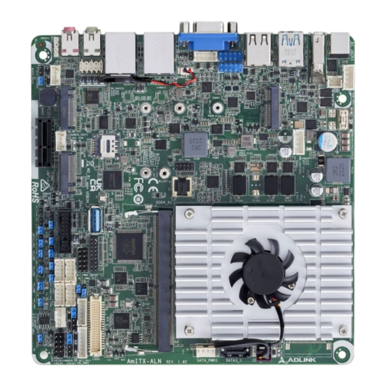
Page 14: Connectors And Jumpers
3.1.2 Connectors and Jumpers 4x USB2.0 M.2 E-Key (USB2H_1~4) (M2_E1) 29 30 31 M.2 M-Key (M2_B1) PCIe Gen3 x1 SIM Card M.2 B-Key (M2_B1) 3* USB 3.2 Gen1 x1 (USB3H_2~4) 4x COM (COM1~4) 11 10 1* SATA3 DDR4 LVDS/eDP (SATA3_1) Mechanical Layout... - Page 15 Front Panel Audio Header (HD_AUDIO1) (PNL_PWR1) System Panel Header (PANEL1) Battery Connector (BAT1) Clear CMOS Header (CLRMOS1) PWR_BAT2 eDP and LVDS Backlight Power Select VGA Header (VGA2) (LCD_BLT_VCC) (BKT_PWR1) 4-pin Chassis FAN Connector (+12V) (CHA_FAN1) Figure 3: AmITX-ALN Component-Side Connectors Mechanical Layout...
- Page 16 This page intentionally left blank. Mechanical Layout...
-
Page 17: Connectors And Jumpers
AmITX-ALN 4 Connectors and Jumpers See 3.1 Connector Locations on page 7. Rear IO Connectors 4.1.1 HDMI One HDMI 2.0b specification port up to 4096 x 2160 @ 60 Hz. Signal Signal HDMI1_CON_DP2 HDMI1_CON_DN2 HDMI1_CON_DP1 HDMI1_CON_DN1 HDMI1_CON_DP0 HDMI1_CON_DN0 HDMI1_CON_CKP HDMI1_CON_CKN... -
Page 18: Led Behavior
10BASE-T/ 1000BASE-T 100BASE-TX LAN_MDI3+ LAN_MDI3- LED Behavior Signal Name Signal Name VGA_CON_RED VGA_CON_GREEN VGA_CON_BLUE +5V_HDMI VGA_DDCDAT VGA_CON_HS VGA_CON_VS VGA_DDCCLK 4.1.4 USB Connectors 1x USB 3.2 Gen2 x1 (Type C) 1x USB 3.2 Gen1 x1 2x USB 2.0 Signal +5VDC USB_N USB_P USB3_RX_N USB3_RX_P... -
Page 19: Audio Connectors
DC Input 4.2.2 SATA Connectors (SATA3_1) One SATA 6 Gbps ports are available on AmITX-ALN. The Serial ATA3 (SATA3) connector supports SATA data cables for internal storage devices and the current SATA3 interface allows up to 6.0 Gb/s data transfer rate. -
Page 20: Usb Cable (Optional)
USB Cable (optional): USB 2.0 Header to 2x Female Type-A Cable (length 150mm), P/N: 30-21625-0000-B0 4.2.4 USB 3.2 Gen1 (USB3H_2-4) 1x USB 3.2 Gen1 Connector (USB3H_2) • 1x USB 3.2 Gen1 Type-A vertical connector on this motherboard. The maximum supported power current is 0.5A. -
Page 21: Front Panel Audio Header (Hd_Audio1)
AmITX-ALN Signal Name Signal Name DUMMY Vbus Vbus USB Cable (optional): USB 3.0 Header to 2x Female Type-A Cable (length 150mm), P/N: 30-21597-1000-A0 4.2.5 Front Panel Audio Header (HD_AUDIO1) This is the line out/microphone interface for the front panel audio cable, allowing jack detection, convenient connection, and control of audio devices. -
Page 22: Serial Com Port Header
4.2.7 Serial COM Port Header There are four 2.54mm-pitch COM port headers (COM1 to COM4) and the serial ports are over-current protected. The maximum current per port is 1A, and the power supply of pin 9 is either 5V or 12V. Use COM Port PWR Setting Jumper to set the power for COM port pin 9. -
Page 23: Lvds Panel Connector (Lvds1)
AmITX-ALN COM Cable (optional): COM Port Cable (length 350mm), P/N: 30-22155-0000-A0 4.2.8 LVDS Panel Connector (LVDS1) Signal Name Signal Name LCD_VCC LCD_VCC +3.3V LVDS_A_DATA0# LVDS_A_DATA0 LVDS_A_DATA1# LVDS_A_DATA1 LVDS_A_DATA2# LVDS_A_DATA2 LVDS_A_DATA3# LVDS_A_DATA3 LVDS_A_CLK# LVDS_A_CLK LVDS_B_DATA0# LVDS_B_DATA0 LVDS_B_DATA1# LVDS_B_DATA1 LVDS_B_DATA2# LVDS_B_DATA2 DPLVDD_EN... -
Page 24: System Panel Header (Panel1)
Signal Name Signal Name EDP_TX0 EDP_AUXN EDP_AUXP DPLVDD_EN CON_LBKLT_EN CON_LBKLT_CTL LCD_BLT_VCC LCD_BLT_VCC LCD_BLT_VCC 4.2.9 System Panel Header (PANEL1) This header accommodates several system front panel functions. Connect the power switch, reset switch, and system status indicator on the chassis to this header according to the pin assignments below. -
Page 25: Chassis Intrusion Header
AmITX-ALN connecting your chassis’s front panel module to this header, make sure the wire and pin assignments match. 4.2.10 Chassis Intrusion Header This motherboard supports CASE OPEN detection feature that determines if the chassis cover has been removed. This feature requires a chassis with chassis intrusion detection design. -
Page 26: M-Key Socket (M2_M1)
4.2.13 4.2.13 M.2 M-Key Socket (M2_M1) Signal Name Signal Name +3.3V +3.3V SATA_LED +3.3V +3.3V +3.3V +3.3V PETp2 USB_D+ USB_D- PERn0 / SATA-B+ PERp0 / SATA-B- PETn0 / SATA-A- PETp0 / PERST# SATA-A+ CLKREQ# PEFCLKn WAKE# PEFCLKp PEDET +3.3V +3.3V Connectors and Jumpers... -
Page 27: B-Key Socket (M2_B1)
AmITX-ALN Signal Name Signal Name +3.3V 4.2.14 M.2 B-Key Socket (M2_B1) Signal Name Signal Name +3.3V +3.3V FULL_Card_ Power_off USB_D+ W_DISABLE1# USB_D- WWAN_LED# W_DISABLE2# USB3_RX- UIM_RESET USB3_RX+ UIM_CLK UIM_DATA USB3_TX- UIM_PWR USB3_TX+ PERn0 PERp0 PETn0 PETp0 PERST# CLKREQ# PEFCLKn WAKE#... -
Page 28: E-Key Socket (M2_E1)
Signal Name Signal Name PEDET +3.3V +3.3V +3.3V 4.2.15 M.2 E-Key Socket (M2_E1) Signal Name Signal Name +3.3V USB_D+ +3.3V USB_D- CNV_WGR_D1- CNV_RF_ RESET CNV_WGR_ MODEM_ CLKREQ CNV_WGR_D0- CNV_WGR_ CNV_WGR_ CNV_BRI_RSP CLK- CNV_WGR_ CLK+ CNV_BGI_DT PETp CNV_RGI_RSP PETn CNV_BRI_DT PERp PERn PEFCLKp PEFCLKn... -
Page 29: Jumper And Switch Settings
AmITX-ALN Signal Name Signal Name SUSCLK CLKREQ# PERST0# W_DISABLE1# W_DISABLE2# CNV_WT_D1- SMB_DATA CNV_WT_D1+ SMB_CLK CNV_WT_D0- CNV_WT_D0+ CNV_WT_CLK- CNV_WT_ +3.3V CLK+ +3.3V Jumper and Switch Settings 4.3.1 ATX/AT Mode Jumper (SIO_AT1) The header provides auto boot function when AC power on. If you need the function, short SIO_AT1 pin 1 and pin 2. - Page 30 From LVDS PWM to CON_LBKLT_CTL (Default) COM Port PWR Setting Headers (PWR_COM1~4 (For COM Port1~4)) • PWR_COM1 (For COM Port1) • PWR_COM2 (For COM Port2) PWR_COM3 (For COM Port3) • PWR_COM4 (For COM Port4) • Setting Description +5V (Default) +12V The maximum current per port is 1A, and the power supply is either 5V or 12V.
- Page 31 AmITX-ALN LCD_BLT_VCC LCD_BLT_VCC Digital Input / Output Power Select (JGPIO_PWR) (JGPIO_PWR1) +12V +5V (Default) eDP and LVDS Panel Power Select (LCD_VCC) (PNL_PWR1) LCD_VCC : +3V (Default) LCD_VCC : +5V LCD_VCC : +12V eDP and LVDS Backlight Power Select (LCD_BLT_VCC) (BKT_PWR1)
-
Page 32: Spdif Out
SPDIF Header (SPDIF1) SPDIF header provides SPDIF audio output to HDMI VGA card, allowing the system to connect to HDMI Digital TV/projector/LCD devices. Connect the SPDIF connector of the HDMI VGA card to this header. Signal Name SPDIF OUT 3W Audio AMP Output Wafer (SPEAKER1) Signal Name OUTLN OUTLP... - Page 33 AmITX-ALN SPI_TPM Header (SPI_TPM1) Signal Name Signal Name TPM PWR RST# MOSI MISO COM3, COM4 TX RX Selection Headers (From left to right) COM4_RX_SEL1 COM4_TX_SEL1 COM3_RX_SEL1 COM3_TX_SEL1 Signal Name TTL: 0V~5V -5V~+5V (RS-232) (Default) Buzzer Header (BUZZ2) This header provides additional external Buzzer to boot up debugging.
- Page 34 This page intentionally left blank. Connectors and Jumpers...
-
Page 35: Driver Installation
AmITX-ALN 5 Driver Installation Drivers can be downloaded through the following link. https://www.adlinktech.com/Products/Industrial_Motherboards_SBCs/Mini-ITXEmbeddedBoards/AmITX-ALN Driver Installation... - Page 36 This page intentionally left blank. Driver Installation...
-
Page 37: Bios Setup
AmITX-ALN 6 BIOS Setup This section presents the primary menus of the UEFI Setup Utility. 2 Options to enter UEFI Setup Utility: Press [F2] or [Del] during POST (Power-On-Self-Test) • Press [Ctl] + [Alt] + [Del] after POST • Menu Structure This section presents the six primary menus of the BIOS Setup Utility. -
Page 38: Main
Main Upon entering the UEFI Setup Utility, the Main Menu is displayed, providing read-only information about your system and allows you to set the system Date and Time. Refer to the screenshots and tables below for details of the submenus and settings. Feature Options System Date... -
Page 39: Advanced > Cpu Configuration
AmITX-ALN 6.3.1 Advanced > CPU Configuration Feature Description Allows you to select the number of E-Cores to enable in each processor package. NOTE: Active Processor E-Cores Number of P-Cores and E-Cores are looked at together. When both are {0,0}, Pcode will enable all cores. -
Page 40: Advanced > Chipset Configuration
6.3.2 Advanced > Chipset Configuration Feature Description VT-d Intel® Virtualization Technology for Directed I/O helps your virtual machine monitor better utilize hardware by improving application compatibility and reliability, and providing additional levels of manageability, security, isolation, and I/O performance. Configuration options: [Enabled] [Disabled] Re-Size BAR Support If a system has Resizable BAR capable PCIe devices, this option enables or disables Resizable BAR Support. -
Page 41: Advanced > Storage Configuration
AmITX-ALN 6.3.3 Advanced > Storage Configuration Feature Description SATA Controller(s) The option allows you to enable or disable the SATA controllers. Configuration options: [Enabled] [Disabled] SATA Mode Selection AHCI supports new features that improve performance. Configuration option: [AHCI] Hybrid Storage Detection and The option allows you to select Hybrid Storage Detection and Configuration Mode. -
Page 42: Advanced > Acpi Configuration
6.3.5 Advanced > ACPI Configuration Feature Description Suspend to RAM Allows you to select [Disabled] for ACPI suspend type S1. It is recommended to select [Auto] for ACPI S3 power saving. Configuration options: [Auto] [Disabled] PCIE Devices Power On Use this item to enable or disable PCIE devices to turn on the system from the power-soft- off mode. -
Page 43: Hw Monitor
AmITX-ALN Feature Description Pending Operation Allows you to schedule an Operation for the Security Device. NOTE: Your computer will reboot during restart in order to change State of the Device. Configuration options: [None] [TPM Clear] Platform Hierarchy Allows you to enable or disable Platform Hierarchy. -
Page 44: Security
Security Feature Description Supervisor Password Set or change the password for the administrator account. Only the administrator has the authority to change the settings in the UEFI Setup Utility. Leave it blank and press enter to remove the password. User Password Set or change the password for the user account. -
Page 45: Save & Exit
AmITX-ALN Save & Exit Feature Description Save Changes and Exit When you select this option, the following message “Save configuration changes and exit setup?” will pop out. Select [Yes] to save the changes and exit the UEFI SETUP UTILITY. Discard Changes and Exit When you select this option, the following message “Discard changes and exit setup?”... -
Page 46: Safety Instructions
Safety Instructions Read and follow all instructions marked on the product and in the documentation before you operate your system. Retain all safety and operating instructions for future use. • Please read these safety instructions carefully. • Please keep this User‘s Manual for later reference. •... -
Page 47: Getting Service
6450 Via Del Oro, San Jose, CA 95119-1208, USA Tel: +1-408-360-0200 Toll Free: +1-800-966-5200 (USA only) Fax: +1-408-600-1189 Email: info@adlinktech.com ADLINK Technology (China) Co., Ltd. Address: 300 Fang Chun Rd., Zhangjiang Hi-Tech Park, Pudong New Area Shanghai, 201203 China Tel: +86-21-5132-8988 Fax: +86-21-5132-3588 Email: market@adlinktech.com...
Need help?
Do you have a question about the AmITX-ALN and is the answer not in the manual?
Questions and answers