
Related Manuals for ADLINK Technology AmITX-BT-I


Summary of Contents for ADLINK Technology AmITX-BT-I
- Page 1 AmITX-BT-I User’s Manual Mini-ITX Embedded Motherboard with 4th Gen Intel® Atom™ Processor E3800 1.00 Manual Revision: November 19, 2015 Revision Date: Part Number: 50-1X011-1000...
-
Page 2: Revision History
Revision History Revision Description Date Initial release 11-19 Page 2 AmITX-BT-I... -
Page 3: Preface
When products are at their end of life, our customers are encouraged to dispose of them in accordance with the product disposal and/or recovery programs prescribed by their nation or company. AmITX-BT-I is a RoHS compliant and leadfree product Trademarks Product names mentioned herein are used for identification purposes only and may be trademarks and/or registered trademarks of their respective companies. -
Page 4: Table Of Contents
4.1.2. Serial COM Ports (COM1, COM2) ......................18 4.1.3. VGA Connector (VGA)........................19 4.1.4. HDMI Connector..........................19 4.1.5. Ethernet Connectors (LAN1, LAN2) ....................20 4.1.6. USB 3.0 Connectors (USB1-4) ......................20 4.1.7. Audio Connectors (Line-out, Mic-in) ....................21 4.2. Internal Connectors ......................21 Page 4 AmITX-BT-I... - Page 5 Main Current .............................39 6.1.3. BMC Status ............................39 6.1.4. Exception Codes ..........................39 6.1.5. BMC Flags ............................40 System Resources ....................41 7.1. System Memory Map ......................41 7.2. I/O Map..........................41 7.2.1. I/O Map .............................41 7.2.2. IRQ Lines PIC mode..........................42 AmITX-BT-I Page 5...
- Page 6 Serial Port Console ..........................61 8.3.12. Thermal ............................62 8.3.13. Miscellaneous..........................62 8.4. Boot ............................ 64 8.4.1. Boot Configuration ..........................64 8.5. Security ..........................65 8.5.1. Password Description ........................65 8.6. Save & Exit .......................... 65 Safety Instructions ...................... 66 Getting Service ......................67 Page 6 AmITX-BT-I...
-
Page 7: Introduction
18/24-bit LVDS. The AmITX-BT-I has dual stacked SODIMM sockets for up to 8 GB non-ECC type DDR3L memory. The AmITX-BT-I features dual Gigabit Ethernet port, USB 3.0 ports and USB 2.0 ports, and SATA 3 Gb/s ports. Support is provided for SMBus and I C. -
Page 8: Specifications
Serial: 2x RS-232 headers, 2x RS-232/422/485 headers with 5V power (12V by BOM option) LVDS: Supports non-EDID type LCD panels only SIM Card Holder: Front Panel Header Audio Header Feature Connector Header PS/2 KB/MS Connector TPM Header SPI Header ATX Power Connector Page 8 AmITX-BT-I... -
Page 9: Form Factor
AT and ATX mode (AT mode start controlled by BMC) Standard Voltage Input: ATX = 12V ±5%, 5Vsb ±5% or AT = 12V ±5% Power Management: ACPI 4.0 compliant Power States: Supports C1-C6, S0, S1, S4, S3, S5, (Wake-on-USB S3/S4, WoL S3/S4/S5) AmITX-BT-I Page 9... -
Page 10: Operating Temperatures
1920 x 1080 @32-bit Intel® Atom™ processor E3845 @ 1.91 GHz Power State Current(A) / Voltage (V) Power (W) Windows 7 (Idle) 0.61/11.82 7.2102 Windows 7 (Typical) 0.92/11.78 10.8376 Windows 7 (Max loading) 1.08/11.77 12.7116 0.3/5.02 1.506 Page 10 AmITX-BT-I... - Page 11 Power Supply FSP FSP600-80PSA 600W ATX Video Resolution 1680 x 1050 @32-bit Power State Current(A) / Voltage (V) Power (W) Windows 7 (Idle) 0.58/12.03 6.9774 Windows 7 (Typical) 0.89/12.03 10.7067 Windows 7 (Max loading) 1.02/12.03 12.2706 0.25/5.00 1.25 AmITX-BT-I Page 11...
-
Page 12: Functional Diagram
2.15. Functional Diagram Page 12 AmITX-BT-I... -
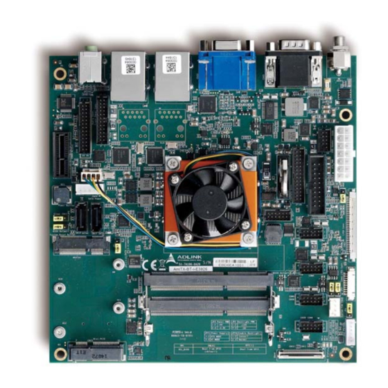
Page 13: Mechanical Layout
Connector USB Header Audio Connector ATX Power PCIe x1 Feature Connector SATA Power TPM Header 2x SATA 3Gb/s SPI Header mSATA Slot LVDS 4x COM Ports Stacked SODIMMs PS/2 KB/MS Mini PCIe DB40 Connector SIM Card Slot AmITX-BT-I Page 13... -
Page 14: Mechanical Dimensions
3.2. Mechanical Dimensions Top View Dimensions: mm All Φ tolerances ±0.05mm Other tolerances ±0.2mm Page 14 AmITX-BT-I... - Page 15 Side View With AmITX-BT_4010- CJ Cooler (Standard Temp.: 0°C to +60°C) With AmITX-BT_4020-CJ Cooler (Extreme Rugged™: -40°C to +85°C, Intel® Atom™ E38xx only) Dimensions: mm All tolerances ±0.2mm AmITX-BT-I Page 15...
-
Page 16: Thermal Solutions
P/N: 32-20493-1000 AmITX-BT_4010- CJ Cooler with Fan Standard Temp.: 0°C to 60°C P/N: 32-20493-0000 AmITX-BT_CU-CJ Passive Heatsink Standard Temp.: 0°C to 60°C P/N: 32-20510-0000 AmITX-BT_4020-CJ Cooler with Fan Extreme Rugged™: -40°C to +85°C (Atom™ E38xx only) P/N: 32-20494-0000 Page 16 AmITX-BT-I... -
Page 17: Connectors And Jumpers
DC Power Inlet The AmITX-BT-I supports a screw-type external 12V DC-in power connector. Maximum current draw is 10A. Note: Either the DC Power Inlet or the internal ATX Power Connector (ATX_PWR) must be used to supply the motherboard with +12V ±5%. -
Page 18: Serial Com Ports (Com1, Com2)
RTX- RXD, Receive Data RTX+ TXD, Transmit Data DTR, Data Terminal Ready DSR, Data Set Ready RTS, Request To Send CTS, Clear To Send RI, Ring Indicator SW14: Switch for mode selection of COM1 (default RS-232). SW14 Page 18 AmITX-BT-I... -
Page 19: Vga Connector (Vga)
TMDS Data2+ TMDS Data2 Shield TMDS Data2– TMDS Data1+ TMDS Data1 Shield TMDS Data1– TMDS Data0+ TMDS Data0 Shield TMDS Data0– TMDS Clock+ TMDS Clock Shield TMDS Clock– Reserved DDC/CEC Ground +5 V Power Hot Plug Detect AmITX-BT-I Page 19... -
Page 20: Ethernet Connectors (Lan1, Lan2)
Status Description Status Description 10 Mb connection No Link Green 100 Mb connection Orange Linked Orange 1 Gb connection Blinking Data Activity 4.1.6. USB 3.0 Connectors (USB1-4) Pin # Signal USB3.0_P5VA USB2_CMAN USB2_CMAP USB3A_CMRXN USB3A_CMRXP USB3A_CMTXN USB3A_CMTXP Page 20 AmITX-BT-I... -
Page 21: Audio Connectors (Line-Out, Mic-In)
4.2.1. ATX Power Connector (ATX_PWR, proprietary) AmITX-BT-I supports a proprietary internal ATX Power Connector (ATX_PWR). An adapter cable is provided for connection to a standard ATX power supply. Note: Either the DC Power Inlet or the internal ATX Power Connector (ATX_PWR) must be used to supply the motherboard with +12V ±5%. -
Page 22: Sata Connectors (Sata1, Sata2)
ATX Power (ATX_PWR) Supply 4.2.2. SATA Connectors (SATA1, SATA2) Two SATA ports are available on the AmITX-BT-I and support SATA Gen2 (3.0/1.5Gb/s). Note: If mSATA is installed, SATA2 is disabled. See 4.3.4 SATA2/mSATA Select (JP1). SATA Power Pin # Signal... -
Page 23: Usb Header
5V/SB5V: 5V supplies for external devices. SB5V is supplied during power down to allow wakeup on USB device activity during S3~S4 state. P5V_USB2 P5V_USB2 CN35 85USB2_P2_DN_R 85USB2_P3_DN_R 85USB2_P2_DP_R 85USB2_P3_DP_R BH_10_S2mm_N9 Pin # Signal Pin # Signal P5V_USB P5V_USB P2_DN_R- P3_DN_R P2_DP_R P3_DP_R USB Cable (optional): USB 2.0 Header to 2x Female Type-A Cable (length 200mm), P/N: 30-20874-1000 AmITX-BT-I Page 23... -
Page 24: Ps/2 Keyboard And Mouse Connector
Note: Signals shared with Audio Connector on Rear I/O. Signal Pin # Pin # Signal LFE-OUT CEN-OUT AAGND AAGND FRONT-OUT-L FRONT-OUT-R AAGND AAGND REAR-OUT-L REAR-OUT-R SIDE-OUT-L SIDE-OUT-R AAGND AAGND MIC1-L MIC1-R AAGND AAGND LINE1-L LINE1-R MUTE AAGND SPDIF-OUT Page 24 AmITX-BT-I... -
Page 25: Cpu Fan And System Fan Connectors
(default RS-232). COM6 COM5 Supports RS-232 only, 5V/12V power support by BOM option (default 5V). COM6 Supports RS-232 only, 5V/12V power support by BOM option (default 5V). RS-232 Pin # Signal Pin # Signal 5V / 12V AmITX-BT-I Page 25... - Page 26 — — — — 5V / 12V SW10/SW11 (RS-422/485 Mode Select) RS-232 (default) RS-422 RS-485 OFF* See Section 4.3.8 Serial Port Mode Switch Setting (SW14, SW10, SW11) COM Cable (optional): COM Port Cable (length 250mm), P/N: 30-20876-0000 Page 26 AmITX-BT-I...
-
Page 27: Lvds Connector
PU 2K2Ω, 3.3V LVDS LVDS A3+ VDD ENABLE 3.3V level LVDS LVDS B0- DDC CLK PU 2K2Ω, 3.3V LVDS LVDS B0+ LCDVCC Max 0.5A Max. 0.5A POWER GND LCDVCC Max 0.5A LVDS LVDS B1- LCDVCC Max 0.5A AmITX-BT-I Page 27... -
Page 28: Lvds Auxiliary Connector
Backlight Power switchable by jumper either 5V (default) or 12V. Maximum 1A per pin for both voltages BKLT_CTL Backlight control, PWM signal to implement voltage in the range 0-3.3V See Chapter 4.3 Jumper and Switch Settings for Backlight Power Selection (JP2), Panel Power Selection (JP3), and Panel Power Selection (JP3) settings. Page 28 AmITX-BT-I... -
Page 29: Front Panel Connector
4.2.11. Front Panel Connector 2x12-pin 2.0 pitch standard wafer connector The front panel connector of AmITX-BT-I provides two USB2.0 header, Audio MIC-In / Line-Out, ATX power switch, Reset, HDD LED, and SUS LED (System Power LED). Pin # Signal Ioh/ Iol... -
Page 30: Feature Connector
4.2.12. Feature Connector 2x13-pin 2.0 pitch standard wafer connector The feature connector of AmITX-BT-I provides Case Open, I C, SMBus, and GPIO(10pin). Signal Description TEMPS Analogue temp sensor, connect to analog input of BMC EXT_BAT Connect to RTC power CASE_OPEN# Any time case open occurred, system will notice/show case open alert in POST when the next booting. -
Page 31: Spi Header
SPI_IO3_#HOLD SPI Data I/O: A bidirectional signal used to support the new Dual IO Fast Read, Quad IO Fast Read and Quad Output Fast Read modes. This signal is not used in Dual Output Fast Read mode. AmITX-BT-I Page 31... -
Page 32: Db40 Debug Board Connector
3.3V provide from BIOS_MODE Connect to Jumper for Program COM module Debug interface 3.3V_BMC always power 3.3V provide from BMC_STATUS COM module Reserved Note: the pin description on the Debug Module is the inverse of that on the motherboard. Page 32 AmITX-BT-I... -
Page 33: Jumper And Switch Settings
ATX (default) 4.3.2. Clear CMOS and BIOS Default (JP5) JPY1 ATX/AT Mode Normal (default) Clear CMOS 4.3.3. Reset BIOS Defaults (JP6) JPY1 ATX/AT Mode Normal (default) Reset BIOS Defaults 4.3.4. SATA2/mSATA Select (JP1) SATA2/mSATA Select SATA2 (default) mSATA AmITX-BT-I Page 33... -
Page 34: Lvds Backlight Power Jumper Selection (Jp2)
LVDS Backlight Power Jumper Selection (JP2) Backlight Power 5V (default) 4.3.6. LVDS Panel Power Jumper Selection (JP3) Panel Power 2-3* 3.3V (default) 4.3.7. LVDS Backlight Enable Jumper Selection (JP4) Backlight Power Active High /Convert 2-3* Active LowNormal (default) Page 34 AmITX-BT-I... -
Page 35: Serial Port Mode Switch Setting (Sw14, Sw10, Sw11)
RS-422 RS-485 SW14 OFF* SW10 (SER3 MODE SEL) SW10 SW11 RS-232 (default) RS-422 RS-485 OFF* SW11 (SER4 MODE SEL) RS-232 (default) RS-422 RS-485 OFF* 4.3.9. BIOS Switch Setting (SW1) ON (default) Boot from SPI0* Boot from SPI1 AmITX-BT-I Page 35... -
Page 36: Onboard Connector Information
LVDS CN21 JVE FI-X30SSLA-HF WELL-LIN WL1058-HL-30P (PH1.0) ENTERPRISE LVDS Auxiliary CN45 Molex 53261-1071 WELL-LIN WL1025-H-10P (PH1.25) ENTERPRISE Feature CN14 JVE 23N6850-28S10B-01G-C-01 JWT A2005H00-2C*14 (PH2.0) Audio 23N6850-26S10B-01G-C-01 JWT A2005H00-2CX13P (PH2.0) Front Panel CN26 JVE 23N6850-24S10B-01G-C-01 JWT A2005H00-2CX13P (PH2.0)- Page 36 AmITX-BT-I... -
Page 37: Driver Installation
5. Driver Installation The AmITX-BT-I drivers for Windows 7 (32-bit/64-bit) and Windows 8 (32-bit/64-bit) can be downloaded from the ADLINK website (www.adlinktech.com/PD/web/PD_detail.php?cKind=&pid=1444). Windows 7 32/64-bit Chipset \1.Chipset\Intel_Chipset_Device_Software_WinAllOS_v10.0.20\ Display \2.Graphic\Intel_HD_Graphics_Win7_32_v36.15.0.1091\ \3.Graphic\Intel_HD_Graphics_Win7_64_v37.15.0.1091\ Audio \4.Audio\Realtek_High_Definition_Audio_Win7_32_64_6.0.1.6410\ \5.LAN\WIN7\Intel_Gigabit_Network_Connection_Win7_32_v12.11.97.1\ \6.LAN\WIN7\Intel_Gigabit_Network_Connection_Win7_64_v12.7.28.0\ \7.IO\Intel_Processor_IO_Drivers_Win7_32_v2.0.msi\ \8.IO\Intel_Processor_IO_Drivers_Win7_64_v2.0.msi\ USB 3.0 \9.USB3.0\Intel_USB 3.0_Host_Controller_Win7_32_64_v3.0.0.34... -
Page 38: Smart Embedded Management Agent (Sema)
(MSB<<8 + LSB) x 3.3 / 1024 +V1.0V (MSB<<8 + LSB) x 3.3 / 1024 +V3.3V (MSB<<8 + LSB) x 1.1 x 3.3 / 1024 +VIN (MSB<<8 + LSB) x 6.000 x 3.3 / 1024 (MAIN CURRENT) Use Main Current Function Page 38 AmITX-BT-I... -
Page 39: Main Current
The Exception Code is not stored in the Flash Storage and is cleared when the power is removed. Therefore, a “Clear Exception Code” command is not needed or supported. Exception Code Error Message NOERROR NO_SUSCLK NO_SLP_S5 NO_SLP_S4 NO_SLP_S3 BIOS_FAIL RESET_FAIL POWER_FAIL LOW_VIN VCORE VGFX V1P05S VMEM AmITX-BT-I Page 39... -
Page 40: Bmc Flags
The BMC Flags register returns the last detected Exception Code since power-up and shows the BIOS in use and the power mode. Description [ 0 ~ 4 ] Exception Code [ 6 ] 0 = AT mode 1 = ATX mode [ 7 ] 0 = Standard BIOS 1 = Fail-safe BIOS. Page 40 AmITX-BT-I... -
Page 41: System Resources
Init Register A0h-A1h, A4h-A5h, A8h-A9h, ACh-ADh, 8259 Slave B0h-B1h,B4h-B5h, B8h-B9h, BCh-BDh, 4D0h-4D1h 2E8h-2FFh COM2 3F8h-3FFh COM1 B2h-B3h Active Power Management E000 Smbus base address for SB. GPIO Base Address for SB PM (ACPI) Base Address for SB AmITX-BT-I Page 41... -
Page 42: Irq Lines Pic Mode
Note (1) Math Processor Primary IDE controller IRQ14 via SERIRQ / PIRQ Note (1) Secondary IDE controller IRQ15 via SERIRQ / PIRQ Note (1) Notes(1): These IRQs can be used for PCI devices when onboard device is disabled. Page 42 AmITX-BT-I... -
Page 43: Irq Lines Apic Mode
PCIE Port 1/2/3/4, AHCI controller, PCI Slot 1/2/3/4 Note (1) Gbe controller, xHCI controller Note (1) Low Power Audio Engine,TXE Note (1) Intel HDA Note (1) Note (1) Notes(1): These IRQs can be used for PCI devices when onboard device is disabled. AmITX-BT-I Page 43... -
Page 44: Pci Configuration Space Map
Internal PCI Express Root port 2 Internal PCI Express Root port 3 Internal PCI Express Root port 4 Internal EHCI USB Platform Controller Unit(LPC) Internal SMBus Controller Internal Texas Instruments PCI-to-PCI Bridge Internal Intel Corporation Ethernet Controller Page 44 AmITX-BT-I... -
Page 45: Pci Interrupt Routing Map
Int3 INTD:19 EHCI Controller SMBus GbE Controller LPSS2 DMA LPSS2 I2C#1 LPSS2 I2C#2 Line Controller Int0 INTH:23 INTE:20 INTB:17 Int1 INTC:18 Int2 INTD:19 Int3 INTC:18 7.5. SMBus Slave Address Device Address DIMM A DIMM B Extend GPIO AmITX-BT-I Page 45... -
Page 46: Bios Setup
- ACPI and ► Power Management - Sound ► - Serial Port ► Console - Thermal ► - Trusted Computing ► - Miscellaneous ► - PPM Configuration ► Notes: ► indicates a submenu Gray text indicates info only Page 46 AmITX-BT-I... -
Page 47: Main
IGFX GOP Version 8.2.4. Memory Information Feature Options Description Total Memory Info only Display total memory information 8.2.5. SOC Information Feature Options Description BayTrail Soc Info only Display SOC stepping TXE FW Version Info only Display version of TXE AmITX-BT-I Page 47... -
Page 48: System Management
Current Input Current Read only Display input current Current Input Power Read only Display input power GPU-Vcore Read only Display actual GPU-Vcore voltage GFX-Vcore Read only Display actual GFX-Vcore voltage V1.05 Read only Display actual V1.05 voltage Page 48 AmITX-BT-I... - Page 49 8.2.6.5. System Management > Flags Feature Options Description Flags Info only BMC Flags Read only BIOS Select Read only Display the selection of current BIOS ROM ATX/AT-Mode Read only Display ATX/AT-Mode Exception Code Read only System exception reason AmITX-BT-I Page 49...
- Page 50 CPU fan the specified PWM level PWM Level Select PWM level CPU Trigger Point 4 Read only Trigger Temperature Specifies the temperature threshold at which the BMC turns on CPU fan the specified PWM level PWM Level Select PWM level Page 50 AmITX-BT-I...
-
Page 51: System Date And Time
Requires the alpha-numeric entry of the day of the week, day of the month, calendar month, and all 4 digits of the year, indicating the century and year (Fri XX/XX/20XX) System Time HH/MM/SS Presented as a 24-hour clock setting in hours, minutes, and seconds AmITX-BT-I Page 51... -
Page 52: Advanced
Disabled Enable/Disable CPU C state report to OS Enabled CPU DTS Disabled Enabled/Disable digital thermal sensor Enabled 8.3.2. Memory Feature Options Description Memory Info only Total Memory Info only Display total memory DIMM#0/1 Info only Display DIMM#0/1 Page 52 AmITX-BT-I... -
Page 53: Graphics
Dual LVDS bus Single /Dual mode select Single LVDS bus DE Polarity Active High DE Polarity select Active Low Vsync Polarity Active High Vsync Polarity Select Active Low Hsync Polarity Active High Hsync Polarity Select Active Low AmITX-BT-I Page 53... -
Page 54: Sata
SATA speed support Gen1 or Gen2. Gen2 Gen3 SATA Port Configuration Submenu 8.3.4.1. SATA > SATA Port Configuration Feature Options Description SATA Port Configuration Info only Port X Disabled Enable/Disable SATA port X. Enabled HotPlug Enabled Enable/Disable SATA port X hotplug. Disabled Page 54 AmITX-BT-I... -
Page 55: Usb
USB Per Port Control Enabled Control each of the USB ports (0~3). Enable: Enable USB per Disabled port; Disable: Use USB port x settings. USB Port #0~3 Enabled Enable/Disable USB port 0-3. Disabled AmITX-BT-I Page 55... -
Page 56: Network
Auto Set maximum read request size of PCI Express device or allow 128 Bytes system BIOS to select the value. 256 Bytes 512 Bytes 1024 Bytes 2048 Bytes 4096 Bytes PCI Express Link Register Settings Info only Page 56 AmITX-BT-I... - Page 57 S3. Enabling this restores PCI Express device configurations on S3 resume. Warning: Enabling this may cause issues with other hardware after S3 resume. PCIe Configuration Info only PCIe Configuration Submenu AmITX-BT-I Page 57...
- Page 58 Enable or disable Root PCI Express System Error on Correctable Error. Enabled PME SCI Disabled Enable or disable PCI Express PME SCI. Enabled Hot Plug Disabled Enable or disable PCI Express hotplug. Enabled Speed Auto Configure PCIe port speed. Gen 2 Gen 1 Page 58 AmITX-BT-I...
-
Page 59: Super Io
Fixed configuration of serial port. Device Settings Auto Select an optimal setting for Super IO device. Change Settings IO=2F8h; IRQ=3 IO=3F8h; IRQ=3,4,5,6,7,10,11,12 IO=2F8h; IRQ=3,4,5,6,7,10,11,12 IO=3E8h; IRQ=3,4,5,6,7,10,11,12 IO=2E8h; IRQ=3,4,5,6,7,10,11,12 Serial Port 5 Configuration Enabled Enable/Disable Serial Port 5 (COM4). AmITX-BT-I Page 59... -
Page 60: Acpi And Power Management
Enabled = Azalia will be unconditionally enabled. Auto = Azalia will be enabled if present, disabled otherwise. Azalia Docking Support Disabled Enable/Disable Azalia docking support of audio controller. Enabled Azalia PME Disabled Enable/Disable power management capability of audio controller. Enabled Page 60 AmITX-BT-I... -
Page 61: Serial Port Console
Resolution 100x31 Disabled Enables or disables extended terminal resolution Enable Legacy OS Redirection 80x24 On legacy OSes, the number of rows and columns supported by redirection 80x25 Putty KeyPad VT100 Select FunctionKey and KeyPad on Putty. LINUX AmITX-BT-I Page 61... -
Page 62: Thermal
Range 2 - 32 8.3.13. Miscellaneous Feature Options Description Miscellaneous Info only High Precision Timer Enabled Enable or disable the High Precision Event Timer. Disabled SCC Configuration Submenu Security Info only BIOS Security Configuration Submenu Trusted Computing Submenu Page 62 AmITX-BT-I... - Page 63 Coniguration Info only Security Device Support Enabled Enables or disables BIOS support for security device. OS will Disabled not show security device. TCG EFI protocol and INT1A interface will not be available. Current Status Information Info only AmITX-BT-I Page 63...
-
Page 64: Boot
Boot option filter UEFI and Legacy This option controls legacy/UEFI ROM priority. Legacy only UEFI only Option ROM execution order Info only Network Do not launch Controls the execution of UEFI and legacy PXE OpROM. UEFI only Legacy only Page 64 AmITX-BT-I... -
Page 65: Security
Restore/Load Default values for all the setup options. Save as User Defaults Yes No Save the changes done so far as User Defaults. Restore User Defaults Yes No Restore the User Defaults to all the setup options. AmITX-BT-I Page 65... -
Page 66: Safety Instructions
Liquid has penetrated the equipment; It has been exposed to high humidity/moisture; It is not functioning or does not function according to the user’s manual; It has been dropped and/or damaged; and/or, It has an obvious sign of breakage. Page 66 AmITX-BT-I... -
Page 67: Getting Service
5215 Hellyer Avenue, #110, San Jose, CA 95138, USA Tel: +1-408-360-0200 Toll Free: +1-800-966-5200 (USA only) Fax: +1-408-360-0222 Email: info@adlinktech.com ADLINK Technology (China) Co., Ltd. Address: 300 Fang Chun Rd., Zhangjiang Hi-Tech Park,Pudong New Area Shanghai, 201203 China Tel: +86-21-5132-8988 Fax: +86-21-5132-3588 Email: market@adlinktech.com... - Page 68 84 Genting Lane #07-02A, Cityneon Design Centre Singapore 349584 Tel: +65-6844-2261 Fax: +65-6844-2263 Email: singapore@adlinktech.com ADLINK Technology Singapore Pte. Ltd. (Indian Liaison Office) Address: #50-56, First Floor, Spearhead Towers Margosa Main Road (between 16th/17th Cross), Malleswaram Bangalore - 560 055, India Tel: +91-80-65605817, +91-80-42246107 Fax:...
Need help?
Do you have a question about the AmITX-BT-I and is the answer not in the manual?
Questions and answers