
Subscribe to Our Youtube Channel
Related Manuals for ADLINK Technology AmITX-AL-I


Summary of Contents for ADLINK Technology AmITX-AL-I
- Page 1 AmITX-AL-I User’s Manual Thin Mini-ITX Embedded Motherboard with Intel Atom™, Pentium , and Celeron ® ® ® Manual Revision: 0.10 preliminary Revision Date: April 6, 2017 Part Number: 50-1J087-1000 Leading EDGE COMPUTING...
-
Page 2: Revision History
AmITX-AL-I Leading EDGE COMPUTING Revision History Revision Description Date 0.10 Preliminary release 2017-04-06... -
Page 3: Preface
When products are at their end of life, our customers are encouraged to dispose of them in accordance with the product disposal and/or recovery programs prescribed by their nation or company. AmITX-AL-I is a RoHS compliant and lead-free product Trademarks Product names mentioned herein are used for identification purposes only and may be trademarks and/or registered trademarks of their respective companies. -
Page 4: Table Of Contents
AmITX-AL-I Leading EDGE COMPUTING Table of Contents Revision History ......................2 Preface..........................3 Introduction ......................7 1.1. Packing List ..........................8 1.2. Optional Accessories ......................8 Specifications......................9 2.1. Core System ...........................9 2.2. Rear I/O Connectors ......................9 2.3. Internal Headers and Connectors..................9 2.4. - Page 5 AmITX-AL-I Leading EDGE COMPUTING 4.2.1. ATX Power Connector 4-pin (ATX_PWR1) ..................19 4.2.2. SATA Connectors (SATA1, SATA2, CN22-23) ..................20 4.2.3. SATA Power Connector (ST_PWR, CN24) ..................20 4.2.4. USB 2.0 Header (CN17)........................21 4.2.5. PS/2 Keyboard and Mouse Connector (CN19) ..................22 4.2.6. Internal Audio Connector (CN16) ......................22 4.2.7.
- Page 6 AmITX-AL-I Leading EDGE COMPUTING 6.3. PCI Configuration Space Map ..................... 42 6.4. PCI Interrupt Routing Map....................43 6.5. SMBus Slave Address......................43 BIOS Setup ......................44 7.1. Menu Structure........................44 7.2. Main............................ 45 7.2.1. BIOS Information ..........................45 7.2.2. System Information ...........................45 7.2.3.
-
Page 7: Introduction
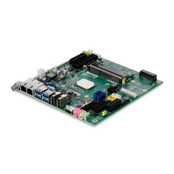
The AmITX-AL-I supports dual stacked SODIMM sockets for up to 16 GB non-ECC type DDR3L memory, and graphics outputs include DisplayPort, HDMI, and optional eDP and optional dual-channel 18/24-bit LVDS. I/O features include HD Audio, dual Gigabit Ethernet port, 4x USB 3.0 ports and 3x USB 2.0 ports, 6x COM ports, PCIe x1 slot, Mini PCIe slot, mSATA slot, and 2x SATA 6 Gb/s ports. -
Page 8: Packing List
AmITX-AL-I Leading EDGE COMPUTING 1.1. Packing List AmITX-AL-I Thin Mini-ITX Embedded Board SATA dual power cable (P/N: 30-20875-0000) SATA cable (P/N: 30-10057-0600) Standard rear I/O shield (P/N: TBD) 1.2. Optional Accessories COM port cable, 1 port (P/N: 30-20876-0000) PS/2 KB/MS cable (P/N: 30-20873-0000) USB 2.0 cable, 2 ports (P/N: 30-20874-1000) -
Page 9: Specifications
AmITX-AL-I Leading EDGE COMPUTING 2. Specifications 2.1. Core System CPU: Dual or quad-core Intel Atom™, Pentium , and Celeron Processor SoC ® ® ® Atom x7-E3950 1.60/2.00 (Burst) GHz 12W (4C/1866) Atom x7-E3940 1.60/1.80 (Burst) GHz 9.5W (4C/1866) Atom x5-E3930 1.30/1.80 (Burst) GHz 6.5W (2C/1866) Pentium N4200 1.10/2.50 (Burst) GHz 6W (4W SDP) (4C/1866) -
Page 10: Form Factor
AmITX-AL-I Leading EDGE COMPUTING 2.4. Form Factor Mini-ITX: 170mm x 170mm 2.5. SEMA Board Controller ADLINK Smart Embedded Management Agent (SEMA) Voltage/Current monitoring Power sequence debug support AT/ATX mode control Logistics and Forensic information Flat Panel Control General Purpose I2C... -
Page 11: Power Specification
AmITX-AL-I Leading EDGE COMPUTING 2.10. Power Specification Power Modes: AT and ATX mode (AT mode start controlled by BMC) Standard Voltage Input: 12VDC ±5% Power Management: ACPI 4.0 compliant Power States: Supports C0, C1, C1E, C6C, C6, C7, S0, S1, S3, S4, S5 (Wake-on-USB S3/S4, WoL S3/S4/S5) 2.11. -
Page 12: Functional Diagram
AmITX-AL-I Leading EDGE COMPUTING 2.14. Functional Diagram eDP (optional) LVDS (eDP) Single/Dual Channel eDP to Horizontal SODIMM Low (Channel A) LVDS LVDS Dat/Clk 18/24-bit 4 lanes DDR3L at 1867/1600 MHz ( non ECC) PTN3460IBS LVDS control LVDS AUX switch Horizontal SODIMM High (Channel B) -
Page 13: Mechanical Layout
AmITX-AL-I Leading EDGE COMPUTING 3. Mechanical Layout 3.1. Connector Locations 3.1.1. Rear I/O 12V DC-in Dual LAN 4x USB 3.0 HDMI Line-out (optional) Mic-in 3.1.2. Top Side Connectors 12V DC-in CPU Fan Feature ATX Power Connector Front Panel SPI Header... -
Page 14: Bottom Side Connectors
AmITX-AL-I Leading EDGE COMPUTING 3.1.3. Bottom Side Connectors microSD Card Slot DB40 Connector SIM Card Slot... -
Page 15: Mechanical Dimensions
AmITX-AL-I Leading EDGE COMPUTING 3.2. Mechanical Dimensions Top View Side View Dimensions: mm... -
Page 16: Connectors And Jumpers
DC Power Inlet The AmITX-AL-I supports a screw-type external 12V DC-in power connector. Maximum current draw is 10A. Note: Either the DC Power Inlet or the internal ATX Power Connector (ATX_PWR) must be used to supply the motherboard with +12V ±5%. -
Page 17: Displayport
AmITX-AL-I Leading EDGE COMPUTING 4.1.2. DisplayPort DisplayPort v1.2 specification ports up to 4096x2160 @ 60Hz (2x DisplayPort by build option, in place of HDMI) Pin # Signal Pin # Signal CN_DP0_P Ground CN_DP0_N CN_DP1_P Ground CN_DP1_N CN_DP2_P Ground CN_DP2_N CN_DP3_P... -
Page 18: Ethernet Connectors (Lan1, Lan2)
AmITX-AL-I Leading EDGE COMPUTING 4.1.4. Ethernet Connectors (LAN1, LAN2) Intel® i211AT (MAC/PHY) Ethernet controller (Intel® i210 is build option for extreme temperature operating range support) Pin # 10BASE-T/100BASE-TX 1000BASE-T LAN_MDI0+ LAN_MDI0- LAN_MDI1+ LAN_MDI2+ LAN_MDI2- LAN_MDI1- LAN_MDI3+ LAN_MDI3- LED1 (Speed) LED2 (Link/Activity) -
Page 19: Audio Connectors (Line-Out, Mic-In)
4.2.1. ATX Power Connector 4-pin (ATX_PWR1) AmITX-AL-I supports a proprietary internal ATX Power Connector (4-pin). Note: Either the DC Power Inlet or the internal ATX Power Connector (4-pin) must be used to supply the motherboard with +12V ±5%. Pin #... -
Page 20: Sata Connectors (Sata1, Sata2, Cn22-23)
AmITX-AL-I Leading EDGE COMPUTING 4.2.2. SATA Connectors (SATA1, SATA2, CN22-23) Two SATA ports are available on the AmITX-AL-I and support SATA Gen3 (6.0/3.0/1.5Gb/s). Note: If mSATA is installed, SATA1 is disabled. See 4.3.3 SATA1/mSATA Select (JP11). Pin # Signal 4.2.3. -
Page 21: Usb 2.0 Header (Cn17)
AmITX-AL-I Leading EDGE COMPUTING 4.2.4. USB 2.0 Header (CN17) 5V/SB5V: 5V supplies for external devices. SB5V is supplied during power down to allow wakeup on USB device activity during S3~S4 state. P5V_USB2 P5V_USB2 CN35 85USB2_P2_DN_R 85USB2_P3_DN_R 85USB2_P2_DP_R 85USB2_P3_DP_R BH_10_S2mm_N9 Pin # Signal... -
Page 22: Ps/2 Keyboard And Mouse Connector (Cn19)
AmITX-AL-I Leading EDGE COMPUTING 4.2.5. PS/2 Keyboard and Mouse Connector (CN19) 6 pin 2.0 pitch standard wafer connector. No support for PS/2 KB/MS wake function Pin # Signal MSCLK V5S_S3 MSDATA KBDATA KBCLK KB/MS Cable (optional): PS/2 KB/MS Cable (length 400mm), P/N: 30-20873-0000 4.2.6. -
Page 23: Cpu Fan And System Fan Connectors (Cpu: Cn36, Sys: Cn37)
AmITX-AL-I Leading EDGE COMPUTING 4.2.7. CPU Fan and System Fan Connectors (CPU: CN36, SYS: CN37) Pin 3 and 4 are connected (monitored and managed) by SEMA controller. Pin # Signal Fan Power (+12V) Fan Sense Fan Speed Control 4.2.8. Serial COM Port Connectors (CN29-CN34) - Page 24 AmITX-AL-I Leading EDGE COMPUTING RS-485 (COM1-2 only) Pin # Signal Pin # Signal Tx/Rx- Tx/Rx+ — — — — — 5V / 12V RS-232/422/485 Selection (COM1-2 only) SW4/SW5 (RS-232/422/485 Mode Select) RS-232 (default) RS-422 RS-485 OFF* COM1 Power selection (JP7, JP8)
-
Page 25: Lvds Connector (Cn13)
AmITX-AL-I Leading EDGE COMPUTING COM Cable (optional): COM Port Cable (length 250mm), P/N: 30-20876-0000 4.2.9. LVDS Connector (CN13) FFC Connector: Female, 30pin, 1mm pitch. (JAE, FI-X30SSLA-HF) Supports non-EDID type LCD panels. Signal Description LVDS A0..A3 LVDS A Channel data LVDS ACLK LVDS A Channel clock LVDS B0..B3... -
Page 26: Lvds Auxiliary Connector (Cn14)
AmITX-AL-I Leading EDGE COMPUTING 4.2.10. LVDS Auxiliary Connector (CN14) Wafer 1x10 pin: 1.25 mm pitch (MOLEX, 53261-1071) Type Signal Note BKLT_EN# 3.3V level Max. 0.5A Max. 0.5A BKLT_PWR Max. 0.5A BKLT_PWR Max. 0.5A BKLT_PWR Max. 0.5A BKLT_PWR Max. 0.5A Max. 0.5A Max. -
Page 27: Front Panel Connector (Cn27)
4.2.11. Front Panel Connector (CN27) 2x12-pin 2.0 pitch standard wafer connector The front panel connector of AmITX-AL-I provides one USB2.0 header, Audio MIC-In / Line-Out, ATX power switch, Reset, HDD LED, and SUS LED (System Power LED). Pin # Signal... -
Page 28: Feature Connector (Cn28)
AmITX-AL-I Leading EDGE COMPUTING 4.2.12. Feature Connector (CN28) 2x14-pin 2.0 pitch standard wafer connector The feature connector of AmITX-AL-I provides Case Open, I2C, SMBus, and GPIO (10pin). Signal Description TEMPS Analogue temp sensor, connect to analog input of BMC EXT_BAT... -
Page 29: Spi Header (Cn40)
AmITX-AL-I Leading EDGE COMPUTING 4.2.13. SPI Header (CN40) 2x6-pin 2.0 pitch standard wafer connector Type Signal Pin # Pin # Signal Type SB3V3 CS0# ADDIN CS1# MOSI ISOLATE MISO SPI_IO2_#WP 11 SPI_IO3_#HOLD IO Signal Description Serial Clock SB3V3 3.3V Standby Voltage power line. Normally output power, but when Motherboard is turned off then the on-board SPI Flash can be 3.3V power sourced via this pin. -
Page 30: Db40 Debug Board Connector
AmITX-AL-I Leading EDGE COMPUTING 4.2.14. DB40 Debug Board Connector FPC Connector Type: FCI 59GF Flex 10042867 Interface Signal Remark Interface Signal Remark VCC_SPI_IN SPI Power Input from flash tool to BMC Program TXD6 Program module. HW need add MOS FET... -
Page 31: Jumper And Switch Settings
AmITX-AL-I Leading EDGE COMPUTING 4.3. Jumper and Switch Settings 4.3.1. ATX/AT Mode Jumper Selection (JP1) ATX/AT Mode ATX (default) 4.3.2. Clear CMOS (JP6) Clear CMOS Normal (default) Clear CMOS 4.3.3. SATA1/mSATA Select (JP11) SATA1/mSATA Select SATA2 (default) mSATA 4.3.4. LVDS Backlight Power Jumper Selection (JP2) -
Page 32: Lvds Panel Power Jumper Selection (Jp3, Jp5)
AmITX-AL-I Leading EDGE COMPUTING 4.3.5. LVDS Panel Power Jumper Selection (JP3, JP5) JP3/JP5 Panel Power 2-3* 3.3V (default) 4.3.6. LVDS Backlight Enable Jumper Selection (JP4) Backlight Power Active High /Convert (default) 2-3* Active LowNormal... -
Page 33: Serial Port Mode Switch Setting (Sw4, Sw5)
AmITX-AL-I Leading EDGE COMPUTING 4.3.7. Serial Port Mode Switch Setting (SW4, SW5) RS-232/422/485 Selection (COM1-2 only) SW4 (SER1 MODE SEL) RS-232 (default) RS-422 RS-485 OFF* SW5 (SER2 MODE SEL) RS-232 (default) RS-422 RS-485 OFF* 4.3.8. Serial Port Power Selection (JP7, JP8, JP9, JP10) -
Page 34: Bios Switch Setting (Bsw1)
AmITX-AL-I Leading EDGE COMPUTING 4.3.9. BIOS Switch Setting (BSW1) BSW1 ON (default) 0 (ON) 1 (OFF) SEL BIOS Boot from SPI0 Boot from SPI1 (Pos. 1-4) (default) BIOS MODE Normal BIOS Failsafe BIOS (Pos. 2-3) (default) -
Page 35: Onboard Connector Information
AmITX-AL-I Leading EDGE COMPUTING 4.4. Onboard Connector Information Onboard Connector Mating Connector Connector ADLINK Cable Manufacturer Part No. Manufacturer Part No. COM Port CN29-34 JVE 23N6850-10S10B-01G-B-01 YOUNG YAK YY-1970H-2*5P (PH2.0) 30-20876-0000 (optional) ATX power Molex 9359-12P E.C.I E.C.I 5016H-2*7P (PH4.2) -
Page 36: Smart Embedded Management Agent (Sema)
AmITX-AL-I Leading EDGE COMPUTING 5. Smart Embedded Management Agent (SEMA) The onboard microcontroller (BMC) implements power sequencing and Smart Embedded Management Agent (SEMA) functionality. The microcontroller communicates via the System Management Bus with the CPU/chipset. The following functions are implemented. -
Page 37: Main Current
AmITX-AL-I Leading EDGE COMPUTING 5.1.2. Main Current The BMC of the cExpress-BT implements a current monitor. The current can be read by calling the SEMA function “Get Main Current”. The function returns four 16-bit values divided in high-byte (MSB) and low-byte (LSB). These 4 values represent the last 4 currents drawn by the board. -
Page 38: Bmc Flags
AmITX-AL-I Leading EDGE COMPUTING Exception Code Error Message VMEM V1P0A V3P3A +P12V_5V CRITICAL_TEMP NO_CB_PWROK NO_HW_PWORK NO_V1P24A_PG 5.1.5. BMC Flags The BMC Flags register returns the last detected Exception Code since power-up and shows the BIOS in use and the power mode. -
Page 39: System Resources
AmITX-AL-I Leading EDGE COMPUTING 6. System Resources 6.1. System Memory Map Address Range (decimal) Address Range (hex) Size Description (4GB-2MB) FFE00000 – FFFFFFFF 2 MB High BIOS Area (4GB-18MB) – (4GB-17MB-1) FEE00000 – FEEFFFFF 1 MB MSI Interrupts (4GB-20MB) – (4GB-19MB-1) FEC00000 –... -
Page 40: Irq Lines Pic Mode
AmITX-AL-I Leading EDGE COMPUTING Hex Range Device CFC-CFF PCI configuration data register 1C00 GPIO Base Address for SB 1800 PM (ACPI) Base Address for SB 1860 Alias for ICH TCO base address. D000-EFFF PCIE Root Port F000-F03F F040-F05F Smbus controller... -
Page 41: Irq Lines Apic Mode
AmITX-AL-I Leading EDGE COMPUTING 6.2.3. IRQ Lines APIC mode IRQ# Typical Intterupt Resource Connected to Pin Available Counter 0 Keyboard controller Cascade interrupt from slave PIC Serial Port 2 (COM2) IRQ3 via SERIRQ / PIRQ Note (1) Serial Port 1 (COM1) -
Page 42: Pci Configuration Space Map
AmITX-AL-I Leading EDGE COMPUTING 6.3. PCI Configuration Space Map Device Function Routing Description Number Number Number Intel Host Bridge Internal Intel VGA Controller Internal Intel HD Audio Device Internal Intel Corporation Communication Device Internal Intel SATA Controller Internal Intel PCIE Root Port 1... -
Page 43: Pci Interrupt Routing Map
AmITX-AL-I Leading EDGE COMPUTING 6.4. PCI Interrupt Routing Map Audio xHCI Line Controller Controller Controller #1 Int0 INTA:25 INTA:None INTA:None Int1 Int2 Int3 PCIE Port 3 PCIE Port 4 PCIE Port 5 PCIE Port 6 Line Int0 INTA:22 INTA:23 INTA:20... -
Page 44: Bios Setup
AmITX-AL-I Leading EDGE COMPUTING 7. BIOS Setup 7.1. Menu Structure This section presents the six primary menus of the BIOS Setup Utility. Use the following table as a quick reference for the contents of the BIOS Setup Utility. The subsections in this section describe the submenus and setting options for each menu item. The default setting options are presented in bold, and the function of each setting is described in the right hand column of the respective table. -
Page 45: Main
AmITX-AL-I Leading EDGE COMPUTING 7.2. Main The Main Menu provides read-only information about your system and also allows you to set the System Date and Time. Refer to the tables below the screen shot of this menu for details of the submenus and settings. -
Page 46: Board Information
AmITX-AL-I Leading EDGE COMPUTING 7.2.3. Board Information 7.2.3.1. Board Information > Board Information Feature Options Description Serial Number Info only Display System Serial Number Manufacturing Date Read only Display Manufacturing Date Last Repair Date Read only Display Last Repair Date... -
Page 47: Advanced
AmITX-AL-I Leading EDGE COMPUTING 7.3. Advanced This menu contains the settings for most of the user interfaces in the system. 7.3.1. CPU Configuration Feature Options Description CPU Configuration Info only Socket 0 CPU Information Submenu Display socket specific CPU Information... - Page 48 AmITX-AL-I Leading EDGE COMPUTING Feature Options Description L1 Code Cache Info only Display L1 Code Cache L2 Cache Info only Display L2 Cache L3 Cache Info only Display L3 Cache 7.3.1.2. CPU Configuration > CPU Power Management Feature Options Description...
-
Page 49: Graphics Configuration
AmITX-AL-I Leading EDGE COMPUTING Feature Options Description Power Limit 1 Time Window Auto Power Limit 1 Time Window value in Seconds. Auto will program Power Limit 1 Time Window based on silicon default support value. 7.3.2. Graphics Configuration Feature Options... -
Page 50: Power Management
AmITX-AL-I Leading EDGE COMPUTING Feature Options Description Hsync Polarity Active High Hsync Polarity select Active Low LVDS Backlight Brightness Value Range A change takes effect immediately. The Value range starts by 0 and ends of 255. 7.3.3. Power Management Feature... -
Page 51: System Management
AmITX-AL-I Leading EDGE COMPUTING 7.3.4. System Management Feature Options Description System Management Info only Version Info only Display Version. SEMA Firmware Read only Display SEMA firmware. Build Date Read only Display SEMA firmware build date SEMA Boot loader Read only Display SEMA boot loader. -
Page 52: Thermal Management
AmITX-AL-I Leading EDGE COMPUTING 7.3.4.2. System Management > Flags Feature Options Description Flags Info only BMC Flags Read only BIOS Select Read only Display the selection of current BIOS ROM. ATX/AT-Mode Read only Display ATX/AT-Mode. Exception Code Read only System exception reason. -
Page 53: Watchdog Timer
AmITX-AL-I Leading EDGE COMPUTING Feature Options Description Trigger Point 1 Read only Trigger Temperature Trigger Temperature PWM Level PWM level Trigger Point 2 Read only Trigger Temperature Trigger Temperature PWM Level PWM level Trigger Point 3 Read only Trigger Temperature... -
Page 54: Csm Configuration
AmITX-AL-I Leading EDGE COMPUTING 7.3.7. CSM Configuration Feature Options Description Compatibility Support Module Configuration Info only CSM Support Enabled Enable/Disable CSM Support Disabled CSM16 Module Version Read Only Display CSM16 Module Version Upon Request GateA20 Active UPON REQUEST - GA20 can be disabled using BIOS services. -
Page 55: Serial Console Redirection
AmITX-AL-I Leading EDGE COMPUTING 7.3.8.1. Super IO > Serial Port 1 Configuration Feature Options Description Serial Port 1 Configuration Info only Serial Port Disabled Enable or Disable Serial Port (COM) Enabled Device Setting Info only Change Setting Auto Select an optimal setting for Super IO Device. - Page 56 AmITX-AL-I Leading EDGE COMPUTING Feature Options Description COM6 Info only Console Redirection Disabled Console Redirection enable or disable. Enabled Console Redirection Settings Submenu The settings specify how the host computer and the remote computer (which the user is using) will exchange data. Both computers should have the same or compatible settings.
-
Page 57: Usb
AmITX-AL-I Leading EDGE COMPUTING 7.3.10. USB Feature Options Description USB Module version Info only USB Controllers: Info only USB Devices: Info only Legacy USB Support Enabled Enables Legacy USB support. Disabled XHCI Hand-off Disabled This is a workaround for OSes without XHCI hand-off support. -
Page 58: Ami Graphic Output Protocol Policy
AmITX-AL-I Leading EDGE COMPUTING 7.3.14. AMI Graphic Output Protocol Policy Feature Options Description Intel(R) Graphics Controller Info only Intel(R) GOP Driver [] Read Only Output Select Output Interface. 7.3.15. SDIO Configuration Feature Options Description SDIO Configuration Info only SDIO/GPIO Mode GPIO Mode Select SDIO or GPIO function. -
Page 59: Chipset
AmITX-AL-I Leading EDGE COMPUTING 7.4. Chipset Feature Options Description North Bridge Submenu North Bridge Parameters South Bridge Submenu South Bridge Parameters Uncore Configuration Submenu Uncore Configuration. South Cluster Configuration Submenu South Cluster Configuration 7.4.1. North Bridge Feature Options Description Memory Information... -
Page 60: Uncore Configuration
AmITX-AL-I Leading EDGE COMPUTING 7.4.3. Uncore Configuration 7.4.3.1. Uncore Configuration > GOP Configuration Feature Options Description Active LFP Config No LFP Active Local Flat Panel Config GTT Mode LVDS Backlight Mode Select LVDS Backlight control function. BMC Mode DDI Port 1... -
Page 61: South Cluster Configuration
AmITX-AL-I Leading EDGE COMPUTING Feature Options Description DVMT Pre-Allocated Select DVMT 5.0 Pre-Allocated (Fixed) Graphics Memory size used 64MB by the Internal Graphics Device. 96MB 128MB 160MB 192MB 224MB 256MB 288MB 320MB 352MB 384MB 416MB 448MB 480MB 512MB DVMT Total Gfx Mem 128M Select DVMT5.0 Total Graphic Memory size used by the Internal... - Page 62 AmITX-AL-I Leading EDGE COMPUTING Feature Options Description PCIe Express Root Port4 Submenu Control the PCI Express Root Port. Auto: To disable unused root port automatically for the most optimum power savings. Enable: Enable PCIE root port Disable: Disable PCIE root port...
- Page 63 AmITX-AL-I Leading EDGE COMPUTING Feature Options Description SENFE Disabled Enable or disable Root PCI Express System Error on Non-Fatal Error. Enabled SECE Disabled Root PCI Express System Error on Correctable Error Enable/Disable. Enabled PME SCI Disabled PCI Express PME SCI Enable/Disable.
- Page 64 AmITX-AL-I Leading EDGE COMPUTING Feature Options Description SATA Test Mode Disabled Test mode Enabled / Disabled Enabled Aggressive LPM Support Disabled Enable PCH to aggressively enter link power state. Enabled SATA Port Configuration Submenu SATA Device Options Settings. SATA Port 0...
- Page 65 AmITX-AL-I Leading EDGE COMPUTING 7.4.4.5. South Cluster Configuration > USB Configuration Feature Options Description XHCI Pre-Boot Driver Disabled Enable/Disable XHCI Pre-Boot Driver Support Enabled XHCI Mode Disabled Once disable, XHCI controller would be function disabled, none of the USB devices are detectable and usable during boot and in OS.
-
Page 66: Security
AmITX-AL-I Leading EDGE COMPUTING 7.5. Security 7.5.1. Password Description Feature Options Description Setup Administrator Password Enter password User Password Enter password Secure Boot menu Submenu Customizable Secure Boot settings. 7.5.1.1. Secure Boot Menu Feature Options Description System Mode Setup Secure Boot... -
Page 67: Safety Instructions
AmITX-AL-I Leading EDGE COMPUTING Safety Instructions Read and follow all instructions marked on the product and in the documentation before you operate your system. Retain all safety and operating instructions for future use. • Please read these safety instructions carefully. -
Page 68: Getting Service
5215 Hellyer Avenue, #110, San Jose, CA 95138, USA Tel: +1-408-360-0200 Toll Free: +1-800-966-5200 (USA only) Fax: +1-408-360-0222 Email: info@adlinktech.com ADLINK Technology (China) Co., Ltd. Address: 300 Fang Chun Rd., Zhangjiang Hi-Tech Park, Pudong New Area Shanghai, 201203 China Tel: +86-21-5132-8988 Fax: +86-21-5132-3588 Email: market@adlinktech.com...
Need help?
Do you have a question about the AmITX-AL-I and is the answer not in the manual?
Questions and answers