
Related Manuals for ADLINK Technology AmITX-BE-G


Summary of Contents for ADLINK Technology AmITX-BE-G
- Page 1 AmITX-BE-G User’s Manual Mini-ITX Embedded Motherboard with 2nd Gen AMD Embedded R-Series APU ® and AMD A77E Fusion Controller Hub ® Manual Revision: 1.01 Revision Date: March 15, 2016 Part Number: 50-1X013-1010...
-
Page 2: Revision History
Revision History Revision Description Date 1.00 Initial release 2015-11-20 1.01 Correct Front Panel CN26 connector information 2016-03-15 Page 2 AmITX-BE-G... -
Page 3: Preface
When products are at their end of life, our customers are encouraged to dispose of them in accordance with the product disposal and/or recovery programs prescribed by their nation or company. AmITX-BE-G is a RoHS compliant and leadfree product Trademarks Product names mentioned herein are used for identification purposes only and may be trademarks and/or registered trademarks of their respective companies. -
Page 4: Table Of Contents
Mechanical Dimensions...................... 14 3.4. Thermal Solutions....................... 16 Connectors and Jumpers ................... 17 4.1. Rear IO Connectors......................17 4.1.1. DisplayPort ............................17 4.1.2. USB Connectors ..........................17 4.1.3. Ethernet Connectors (LAN1, LAN2) ....................18 4.1.4. Audio Connectors ..........................18 4.2. Internal Connectors ......................19 Page 4 AmITX-BE-G... - Page 5 6.1.3. BMC Status ............................37 6.1.4. Exception Codes ..........................37 6.1.5. BMC Flags ............................38 System Resources ....................39 7.1. System Memory Map ......................39 7.2. Direct Memory Access Channels ..................39 7.3. I/O Map..........................40 7.3.1. I/O Map .............................40 AmITX-BE-G Page 5...
- Page 6 Trusted Computing..........................58 8.3.13. Thermal ............................58 8.3.14. Miscellaneous..........................59 8.4. Boot ............................ 59 8.4.1. Boot Configuration ..........................59 8.5. Security ..........................60 8.5.1. Password Description ........................60 8.6. Save & Exit .......................... 61 Safety Instructions ...................... 62 Getting Service ......................63 Page 6 AmITX-BE-G...
-
Page 7: Introduction
The AmITX-BE-G features four DisplayPorts, dual Gigabit Ethernet port, USB 3.0 ports, USB 2.0 ports, SATA 6 Gb/s ports, and High Definition Audio with 7.1 channels. Support is provided for one PCIe x16, one PCIe x1, and two Mini PCIe slots. A feature connector provides access to GPIO, SMBus, and I2C signals. -
Page 8: Specifications
Embedded BIOS: AMI EFI in 8MB SPI BIOS 2.2. Rear I/O Connectors Display: 4x DisplayPort (AmITX-BE-G-LVDS SKU: 3x DisplayPort) LAN: Dual GbE RJ-45 USB: 4x USB 3.0, 4x USB 2.0 Audio: 7.1 channel audio via 5 jacks and S/PDIF output on rear I/O 2.3. -
Page 9: Sema Board Controller
LVDS (optional): single/dual channel 18/24-bit LVDS (through eDP to LVDS bridge IC) 2.8. Audio Audio Codec: Realtek ALC886 2.9. Intel MAC/PHY: Intel® i211AT (MAC/PHY) Ethernet controller Interface: 10/100/1000 GbE connection 2.10. Trusted Platform Module (TPM) Chipset: Atmel AT97SC3204 (optional) Type: TPM1.2 AmITX-BE-G Page 9... -
Page 10: Power Specification
MIL-STD-202F, Method 213B, Table 213-I, Condition A and Method 214A, Table 214-I, Condition D HALT: Thermal Stress, Vibration Stress, Thermal Shock and Combined Test 2.14. Operating Systems Standard Support: Windows 7/8 32/64-bit, Linux 32/64-bit Extended Support (BSP): WES7, WE8S, Linux Page 10 AmITX-BE-G... -
Page 11: Power Consumption
2.16/12.14 26.2224 Windows 7 (Max loading) 2.22/12.14 26.9508 2.23/12.14 27.0722 0.23/5.01 1.1523 0.15/5.01 0.7515 Notes: (1) Typical mode measurement when running BurnInTest. (2) Max loading measurement when running AMD System Stress Test. (3) S1 state not supported. AmITX-BE-G Page 11... -
Page 12: Functional Diagram
COM2 header Super I/ COM3 header COM4 header SPI0/1 header 3x RS-232 SPI 0/1 SPI2 socket SPI0 (optional) PS/2 SPI1 Atmel CPU FAN SMbus SYS FAN 1 SYS FAN 2 Sensor GPIO Feature Connector GPIO System signals Page 12 AmITX-BE-G... -
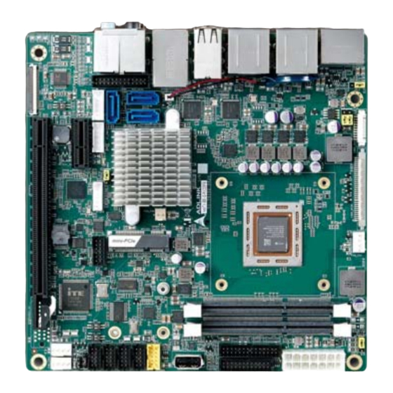
Page 13: Mechanical Layout
PCIe x16 USB Vertical Connector PS/2 KB/MS 2x SODIMM SPI Socket Feature Connector SPI Header Front Panel Connector USB 2.0 ATX/AT Power 3x RS-232 1x RS-232/422/485 3.2. Rear IO Connectors USB 3.0 USB 3.0 USB 2.0 Audio AmITX-BE-G Page 13... -
Page 14: Mechanical Dimensions
3.3. Mechanical Dimensions Top View Dimensions: mm All tolerances ±0.2mm Page 14 AmITX-BE-G... - Page 15 Side View Dimensions: mm All tolerances ±0.2mm AmITX-BE-G Page 15...
-
Page 16: Thermal Solutions
3.4. Thermal Solutions 5010-CU-CJ APU Cooler Standard Temp.: 0°C to 60°C P/N: 32-20478-0000 5010-AL-RG APU Cooler Standard Temp.: 0°C to 60°C P/N: 32-20499-0000 Page 16 AmITX-BE-G... -
Page 17: Connectors And Jumpers
5Vsb is supplied during power down to allow wakeup on USB device activity during S3~S4 state 1.5A for device power supply protected by a resettable 2A fuse USB 2.0: Pin # Signal UV0- UV0+ USB 3.0: Pin # Signal USB3.0_P5VA USB2_CMAN USB2_CMAP USB3A_CMRXN USB3A_CMRXP USB3A_CMTXN USB3A_CMTXP AmITX-BE-G Page 17... -
Page 18: Ethernet Connectors (Lan1, Lan2)
Description 10 Mb connection No Link Green 100 Mb connection Orange Linked Orange 1 Gb connection Blinking Data Activity 4.1.4. Audio Connectors 7.1 channel audio via 5 jacks and S/PDIF output on rear I/O Realtek ALC886 codec Page 18 AmITX-BE-G... -
Page 19: Internal Connectors
AmITX-HL-G supports a proprietary internal ATX Power Connector (ATX_PWR). An adapter cable is provided for connection to a standard ATX power supply. Pin # Signal Pin # Signal SB5V P_OK PS_ON# +12V +12V +12V +12V 3.3V ATX Adapter Cable: ADLINK Part. No. 30-20872-0000 (length 250 mm) Motherboard ATX Power Connector ATX Power (ATX_PWR) Supply AmITX-BE-G Page 19... -
Page 20: Sata Connectors (Sata0/1/2)
Three SATA 6 Gbps ports are available on the AmITX-HL-G (H81: 2x SATA 6 Gbps and 1x SATA 3 Gbps). Pin # Signal 4.2.3. SATA Power Connector (ST_PWR1/2) Pin # Signal 3.3V SATA Power Cable: ADLINK Part. No.: 30-20875-0000 (length 200 mm) HDD/SSD Power HDD/SSD Power Motherboard SATA Power Connector Page 20 AmITX-BE-G... -
Page 21: Usb Header
5V/SB5V: 5V supplies for external devices. SB5V is supplied during power down to allow wakeup on USB device activity during S3~S4 state. P5V_USB2 P5V_USB2 CN35 85USB2_P2_DN_R 85USB2_P3_DN_R 85USB2_P2_DP_R 85USB2_P3_DP_R BH_10_S2mm_N9 Pin # Signal Pin # Signal P5V_USB P5V_USB P2_DN_R- P3_DN_R P2_DP_R P3_DP_R USB Cable (optional): USB 2.0 Header to 2x Female Type-A Cable (length 200mm), P/N: 30-20874-1000 AmITX-BE-G Page 21... -
Page 22: Ps/2 Keyboard And Mouse Connector
Note: Signals shared with Audio Connector on Rear I/O. Signal Pin # Pin # Signal LFE-OUT CEN-OUT AAGND AAGND FRONT-OUT-L FRONT-OUT-R AAGND AAGND REAR-OUT-L REAR-OUT-R SIDE-OUT-L SIDE-OUT-R AAGND AAGND MIC1-L MIC1-R AAGND AAGND LINE1-L LINE1-R MUTE AAGND SPDIF-OUT Page 22 AmITX-BE-G... -
Page 23: Cpu Fan And System Fan Connectors
5V/12V power support by jumper select (JPS3P, default NC). SWS1M: Switch for mode selection of SER1 (default RS-232). SER2 Supports RS-232 only SER3 Supports RS-232 only SER4 Supports RS-232 only RS-232 Pin # Signal Pin # Signal 5V / 12V AmITX-BE-G Page 23... - Page 24 — — — 5V / 12V SER1 Mode Switch (SWS1M) SWS1M (SER1 MODE SEL) RS-232 (default) RS-422 RS-485 Note: See Section 4.3.5COM Port (SER1) Power Selection (JPS3P) COM Cable (optional): COM Port Cable (length 250mm), P/N: 30-20876-0000 Page 24 AmITX-BE-G...
-
Page 25: Lvds Connector
PU 2K2Ω, 3.3V LVDS LVDS A3+ VDD ENABLE 3.3V level LVDS LVDS B0- DDC CLK PU 2K2Ω, 3.3V LVDS LVDS B0+ LCDVCC Max 0.5A Max. 0.5A POWER GND LCDVCC Max 0.5A LVDS LVDS B1- LCDVCC Max 0.5A AmITX-BE-G Page 25... -
Page 26: Lvds Auxiliary Connector
Backlight Power switchable by jumper either 5V (default) or 12V. Maximum 1A per pin for both voltages BKLT_CTL Backlight control, PWM signal to implement voltage in the range 0-3.3V See Section 4.3 Jumper and Switch Settings for Backlight Power Selection (JPL1), Panel Power Selection (JPL2), and Backlight Enable Jumper Selection (JPL3) settings. Page 26 AmITX-BE-G... -
Page 27: Front Panel Connector
The LED is on when the system is operating. The LED keeps blinking when the system is in S1/S3 sleep state. The LED is off when the system is in S4 sleep state or powered off (S5). AmITX-BE-G Page 27... -
Page 28: Feature Connector
GPIO6 PU10K3V3 IOT GPIO7 PU10K3V3 GPIO8 PU10K3V3 IOT GPIO9 PU10K3V3 SUS_S3# O 25/25mA - SUS_S4# O 25/25mA - PWR_OK 25/25mA SUS_S5# O 25/25mA - Note 1: Pull-up to +3V3Dual (+3V3 or SB3V3). Note 2: Input to SEMA. Page 28 AmITX-BE-G... -
Page 29: Spi Header
SPI_IO3_#HOLD SPI Data I/O: A bidirectional signal used to support the new Dual IO Fast Read, Quad IO Fast Read and Quad Output Fast Read modes. This signal is not used in Dual Output Fast Read mode. AmITX-BE-G Page 29... -
Page 30: Db40 Debug Board Connector
3.3V provide from BIOS_MODE Connect to Jumper for Program COM module Debug interface 3.3V_BMC always power 3.3V provide from BMC_STATUS COM module Reserved Note: the pin description on the Debug Module is the inverse of that on the motherboard. Page 30 AmITX-BE-G... -
Page 31: Jumper And Switch Settings
BIOS Switch (JPL2) (SW2) SER1 Mode Switch (SWS1M) SER1 Power Selection (JPS3P) ATX/AT Mode Jumper (JPATX) Mini-PCIe/mSATA Selection (JPMSATA) 4.3.2. ATX/AT Mode Selection (JPATX) JPATX_BOOT MODE ATX (default) 4.3.3. Clear CMOS (CMOS) CMOS Normal (default) Clear CMOS AmITX-BE-G Page 31... -
Page 32: Mini-Pce/Msata Selection (Jpmsata)
COM Port (SER1) Power Selection (JPS3P) JPS3P (SER1 PWR SEL) NC (default) 4.3.6. LVDS Backlight Power Selection (JPL1) JPL1_BKLTPWR 5V (default) 4.3.7. LVDS Panel Power Selection (JPL2) JPL2_PANELPWR 3.3V (default) 4.3.8. LVDS Backlight Enable Selection (JPL3) JPL3_BKLTEN Active High Active Low (default) Page 32 AmITX-BE-G... -
Page 33: Bios Switch Setting (Sw2, Sw3)
Failsafe Mode (default): Boot up by SPI0 with fail safe SPI0 + SPI1 support. Fail Safe SPI0 + SPI1 (default ) Normal BIOS Mode: Boot up from SPI0 Boot up by SPI0 Normal BIOS Mode: Boot up by SPI2 (optional socket SPI) Boot up by SPI2 AmITX-BE-G Page 33... -
Page 34: Onboard Connector Information
Molex 502790-4091 30-30016-0000 (optional) LVDS CN21 FI-X30SSLA-HF WELL-LIN WL1058-HL-30P (PH1.0) ENTERPRISE LVDS Auxiliary CN45 Molex 53261-1071 WELL-LIN WL1025-H-10P (PH1.25) ENTERPRISE Feature CN14 23N6850-28S10B-01G-C-01 JWT A2005H00-2C*14 (PH2.0) Audio 23N6850-26S10B-01G-C-01 JWT A2005H00-2CX13P (PH2.0) Front Panel CN26 23N6850-24S10B-01G-C-01 YY-1970H-2*12P (PH2.0) Page 34 AmITX-BE-G... -
Page 35: Driver Installation
Install the Controller Hub-A77E driver by running the program \5.AHCI_Driver_1_3_1\AHCI_Driver_1_3_1_220\Setup.exe. Follow the instructions given and reboot if required. Install the IOMMU driver by Device manager. Find other devices\PCI Device and click “Update Driver”. Find \6.AmdIOV\ folder and install driver. AmITX-BE-G Page 35... -
Page 36: Smart Embedded Management Agent (Sema)
(MSB<<8 + LSB) x 3.3 / 1024 +V1.0V (MSB<<8 + LSB) x 3.3 / 1024 +V3.3V (MSB<<8 + LSB) x 1.1 x 3.3 / 1024 +VIN (MSB<<8 + LSB) x 6.000 x 3.3 / 1024 (MAIN CURRENT) Use Main Current Function Page 36 AmITX-BE-G... -
Page 37: Main Current
The Exception Code is not stored in the Flash Storage and is cleared when the power is removed. Therefore, a “Clear Exception Code” command is not needed or supported. Exception Code Error Message NOERROR NO_SUSCLK NO_SLP_S5 NO_SLP_S4 NO_SLP_S3 BIOS_FAIL RESET_FAIL POWER_FAIL LOW_VIN VCORE VGFX V1P05S VMEM AmITX-BE-G Page 37... -
Page 38: Bmc Flags
The BMC Flags register returns the last detected Exception Code since power-up and shows the BIOS in use and the power mode. Description [ 0 ~ 4 ] Exception Code [ 6 ] 0 = AT mode 1 = ATX mode [ 7 ] 0 = Standard BIOS 1 = Fail-safe BIOS. Page 38 AmITX-BE-G... -
Page 39: System Resources
0 K – 640 K 00000 – 9FFFF 640 KB DOS Area 7.2. Direct Memory Access Channels Channel Number Data Width System Resource 8-bits Open Open 8-bits Open 8-bits Open 8-bits Direct Memory Access Controller 16-bits Open 16-bits Open 16-bits Open AmITX-BE-G Page 39... -
Page 40: I/O Map
Serial port 2 3E8-3EF Serial port 3 3F8-3FF Serial port 1 SMBUS IO base Reset Control register (8 bit I/O) Note (1): A read to this address will subtractive decode from PCI, where it will master abort. Page 40 AmITX-BE-G... -
Page 41: Irq Lines Pic Mode
Serial Port 4 High precision even timer Numeric data processor ATA Channel 0 ATA Channel 1 High Definition Audio Controller Standard Enhanced PCI to USB Host Controller Standard OpenHCD USB Host Controller AMD SATA Controller High Definition Audio Controller AmITX-BE-G Page 41... -
Page 42: Pci Configuration Space Map
AMD PCI-to-PCI Bridge#2 Internal AMD PCI-to-PCI Bridge#3 AMD Host Bridge#0 AMD Host Bridge#1 AMD Host Bridge#2 AMD Host Bridge#3 AMD Host Bridge#4 AMD Host Bridge#5 Internal Intel Ethernet controller (PCI Express) Internal Intel Ethernet controller (PCI Express) Page 42 AmITX-BE-G... -
Page 43: Pci Interrupt Routing Map
INTD INTB INTD INTB INTC INTD INTA INTE INTC INTD INTA INTB INTF INTD INTA INTB INTC 7.6. SMBus Address Table Device Address 0x40 PCA9535BS 0x50 SEMA 0xA0 DIMM A 0xA4 DIMM B 0xC0 NXP (LVDS SKU) AmITX-BE-G Page 43... -
Page 44: Bios Setup
- Super IO ► - ACPI and ► Power Management - Sound ► - Serial Port ► Console - Trusted ► Computing - Thermal ► - Miscellaneous ► Notes: ► indicates a submenu Gray text indicates info only Page 44 AmITX-BE-G... -
Page 45: Main
Options Description Temperatures and Fan Info only CPU Temperature Info only Current Read only Display current CPU temperature Startup Read only Display CPU startup temperature Read only Display CPU min. temperature Read only Display CPU max. temperature AmITX-BE-G Page 45... - Page 46 Boot Cycles Read only The Bootcounter is increased after a HW- or SW-Reset or after a successful power-up. Boot Reason Read only The boot reason is the event which causes the reboot of the system. Page 46 AmITX-BE-G...
- Page 47 Specifies the temperature threshold at which the BMC turns on the CPU fan with the specified PWM level PWM Level Select PWM level Trigger Point 2 Read only Trigger Temperature Specifies the temperature threshold at which the BMC turns on AmITX-BE-G Page 47...
- Page 48 Specifies the temperature threshold at which the BMC turns on the System fan2 with the specified PWM level PWM Level Select PWM level Trigger Point 2 Read only Trigger Temperature Specifies the temperature threshold at which the BMC turns on Page 48 AmITX-BE-G...
-
Page 49: System Date And Time
L1 Instruction Cache Info only Display cache info L1 Data Cache Info only Display cache info L2 Cache Info only Display cache info L3 Cache Info only Display cache info Module Version Info only Display CPU Module Version AmITX-BE-G Page 49... -
Page 50: Memory
This Option Allows User to select different Memory Clock. Default value is 800Mhz. 800MHz 1066MHz 1333MHz 1600MHz 1866MHz 8.3.3. Graphics Feature Options Description Graphics Info only IGD VBIOS Version Info only IOMMU Disabled Enable/Disable IOMMU Support Enabled Integrated Graphics Auto Enable Integrate Graphics Controller Disabled Force Page 50 AmITX-BE-G... -
Page 51: Sata
Legacy mode Native mode SATA PortX Info only ESATA PORT on PORTX Disabled SATA port X support ESATA Enable/disable Enabled SATA Power on PORTX Enabled SATA port Power Enable/disable Power Down SATA PORTX MODE Auto GEN1 GEN2 AmITX-BE-G Page 51... -
Page 52: Usb
Description Network Info only Network Stack Disabled Enable/Disable UEFI network stack. Enabled UEFI PXE Driver Disabled Enable/Disable UEFI PXE Driver. Enabled LAN1 device enable/disable Disabled LAN1 device enable/disable Enabled LAN2 device enable/disable Disabled LAN2 device enable/disable Enabled Page 52 AmITX-BE-G... -
Page 53: Pci And Pcie
PCI Express Link Register Settings Info only ASPM Support Disabled Set the ASPM Level: Force L0s - Force all links to L0s Auto Auto - BIOS auto configure WARNING: Enabling ASPM may cause Force L0s Disabled - Disables ASPM some AmITX-BE-G Page 53... - Page 54 If supported by hardware and set to 'Force to 2.5 GT/s' for Downstream Ports, this sets an upper limit on Link operational Force to 2.5 GT/s speed by restricting the values advertised by the Upstream Force to 5.0 GT/s component in its training sequences. When 'Auto' is selected Page 54 AmITX-BE-G...
- Page 55 UMI Gen2 Disabled Enabled GPP HW Compliance Mode Disabled Port A Port B Port C Port D SB GPP LANE REVERSAL Disabled Enabled UMI PHY PLL Power Down Disabled Enabled SB GPP PHY PLL Power Down Disabled Enabled AmITX-BE-G Page 55...
-
Page 56: Usb
Enabled Enable/Disable Serial Port 4 (COM3). Disabled Device Settings IO=2F8h; IRQ=6 Fixed configuration of serial port. Change Settings Auto Select an optimal setting for Super IO device. IO=2E8h; IRQ=6 IO=3F8h; IRQ=3,4,5,6,7,10,11,12 IO=2F8h; IRQ=3,4,5,6,7,10,11,12 IO=3E8h; IRQ=3,4,5,6,7,10,11,12 IO=2E8h; IRQ=3,4,5,6,7,10,11,12 Page 56 AmITX-BE-G... -
Page 57: Acpi And Power Management
VT-UTF8 more bytes. ANSI ANSI: Extended ASCII char set. Bits per second 9600 Selects serial port transmission speed. The speed must be matched on the remote computer. Long or noisy lines may 19200 require lower speeds. 38400 AmITX-BE-G Page 57... -
Page 58: Trusted Computing
Info only 8.3.13. Thermal Feature Options Description Thermal Info only Active Cooling Trip Point Disabled This value is the temperature threshold of the Active Cooling Trip Point. 40 C 50 C 60 C 70 C BMC Default Page 58 AmITX-BE-G... -
Page 59: Miscellaneous
Info only CSM16 Parameters Submenu CSM16 configuration:GateA20 Active, Option ROM Message,Int19 Trap Response, etc. CSM Parameters Submenu CSM configuration: Enable/Disable, Option ROM execution settings, etc. 8.4.1.1. Boot Configuration > CSM16 Parameters Feature Options Description CSM16 Parameters Info AmITX-BE-G Page 59... -
Page 60: Security
Customizable Secure Boot settings. 8.5.1.1. Secure Boot Menu Feature Options Description System Mode Setup Secure Boot Info only Secure Boot Disabled Secure Boot can be enabled if: 1. System running in User mode with enrolled Platform Key (PK) Enabled Page 60 AmITX-BE-G... -
Page 61: Save & Exit
Restore/Load Default values for all the setup options. Save as User Defaults Yes No Save the changes done so far as User Defaults. Restore User Defaults Yes No Restore the User Defaults to all the setup options. AmITX-BE-G Page 61... -
Page 62: Safety Instructions
Liquid has penetrated the equipment; It has been exposed to high humidity/moisture; It is not functioning or does not function according to the user’s manual; It has been dropped and/or damaged; and/or, It has an obvious sign of breakage. Page 62 AmITX-BE-G... -
Page 63: Getting Service
5215 Hellyer Avenue, #110, San Jose, CA 95138, USA Tel: +1-408-360-0200 Toll Free: +1-800-966-5200 (USA only) Fax: +1-408-360-0222 Email: info@adlinktech.com ADLINK Technology (China) Co., Ltd. Address: 300 Fang Chun Rd., Zhangjiang Hi-Tech Park, Pudong New Area Shanghai, 201203 China Tel: +86-21-5132-8988 Fax: +86-21-5132-3588 Email: market@adlinktech.com... - Page 64 84 Genting Lane #07-02A, Cityneon Design Centre Singapore 349584 Tel: +65-6844-2261 Fax: +65-6844-2263 Email: singapore@adlinktech.com ADLINK Technology Singapore Pte. Ltd. (Indian Liaison Office) Address: #50-56, First Floor, Spearhead Towers Margosa Main Road (between 16th/17th Cross), Malleswaram Bangalore - 560 055, India Tel: +91-80-65605817, +91-80-42246107 Fax:...
Need help?
Do you have a question about the AmITX-BE-G and is the answer not in the manual?
Questions and answers