
Subscribe to Our Youtube Channel
Related Manuals for ADLINK Technology AmITX-RL-I


Summary of Contents for ADLINK Technology AmITX-RL-I
- Page 1 AmITX-RL-I User’s Manual Mini-ITX Embedded Motherboard with Gen Intel® Core™ i9/i7/i5/i3 Processors and Intel® Q670 Chipset Manual Rev.: Revision Date: July 15, 2024 Part Number: 50M-16008-1000...
- Page 2 Preface Copyright Copyright © 2024 ADLINK Technology, Inc. This document contains proprietary information protected by copyright. All rights are reserved. No part of this manual may be reproduced by any mechanical, electronic, or other means in any form without prior written permission of the manufacturer.
- Page 3 AmITX-RL-I Table of Contents Preface ..........................ii List of Figures ........................iv Introduction ........................ 1 Packing List ........................1 Optional Accessories ..................... 1 Specifications ......................3 Core System ......................... 3 Rear I/O Connectors ..................... 4 Internal Headers and Connectors .................. 5 Form Factor........................
- Page 4 List of Figures Figure 1: AmITX-RL-I Functional Block Diagram ..................8 Figure 2: AmITX-RL-I Rear I/O ......................... 9 Figure 3: AmITX-RL-I Component-Side Connectors ................10 Preface...
- Page 5 The AmITX-RL-I features one DisplayPort, two HDMI, one LVDS or eDP, 2.5 and 1 Gigabit Ethernet ports, USB 3.2 Gen 2 and Gen 1 ports, USB 2.0 ports, and SATA 6 Gb/s ports. Expansion is provided by one PCIe Gen 5 x16 slot.
- Page 6 This page intentionally left blank. Introduction...
- Page 7 AmITX-RL-I 2 Specifications Core System Desktop 12th/13th/14th Generation Intel® Core™ i9/i7/i5/i3 and Pentium®/Celeron® Processor, LGA1700 socket Family Number CPU Core Frequency (GHz) Cache (MB) Power Alder Lake-S i9-12900TE 1.1GHz 30MB Alder Lake-S i9-12900E 2.3GHz 30MB Alder Lake-S i7-12700TE 1.4GHz 25MB...
- Page 8 Raptor Lake-S i5-14500 2.6GHz 24MB Refresh Raptor Lake-S i5-14400T 1.5GHz 20MB Refresh Raptor Lake-S i5-14400 2.5GHz 20MB Refresh Raptor Lake-S i3-14100T 2.7Ghz 12MB Refresh Raptor Lake-S i3-14100 3.5GHz 12MB Refresh Raptor Lake-S 300T 3.4GHz Refresh Raptor Lake-S 3.9GHz Refresh Note: Availability of features may vary between processor SKUs and operating systems. Chipset Intel®...
- Page 9 AmITX-RL-I Internal Headers and Connectors PCI Express Slots 1x PCIe Gen5 x16 2x USB3.2 Gen1 x1 (via header) 2x USB2.0 (via header) SATA 4x SATA 6.0 Gb/s connectors. Software RAID support 0/1/5/10 Expansion Slots 1x M.2 B-key 3042/3052 (PCIe x1, USB3.2 Gen1, USB 2.0) for 4G/5G module 1x M.2 E-key 2230 (PCIe x1, USB 2.0, CNVi) for Wireless...
- Page 10 Video Controller Intel® UHD Graphics Display Interface 1x HDMI 2.0b, max resolution up to 4096x2160@60Hz • Support 1x HDMI 1.4b, max resolution up to 4096x2160@30Hz • 1x DP 1.4a, DP++, max resolution up to 4096x2160@60Hz • • 1x LVDS, supports dual channel 24-bit, max resolution up to 1920x1200@60Hz (Connector shared with eDP) Audio Audio Codec...
- Page 11 AmITX-RL-I 2.10 Watchdog Timer Output From Super I/O to drag RESETCON# 256 Segments, 0, 1, 2, ...255 Sec Interval 2.11 Temperatures Standard Operating -20°C to 70°C Temperature Storage -40°C to 85°C Temperature 2.12 Environmental Humidity 60°C @ 95% RH non-condensing...
- Page 12 2.14 Functional Block Diagram Figure 1: AmITX-RL-I Functional Block Diagram Specifications...
- Page 13 3.1.1 Rear I/O Connectors 2x COM LAN2 LAN1 (COM1,2) DP1.4a 1 GbE 2.5 GbE Audio Output: Green - Line Out 2x USB2.0 4x USB3.2 Gen2 HDMI2.0b Audio Output: Pink - Mic In HDMI1.4b Figure 2: AmITX-RL-I Rear I/O Mechanical Layout...
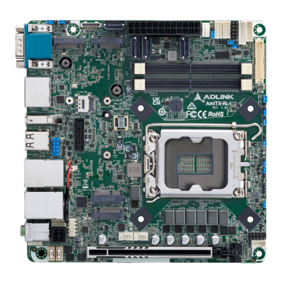
- Page 14 (COM3,4) 19 20 24 25 26 22 23 LVDS/eDP 2x DDR5 SIM socket 2x USB3.2 Gen1 Header 2x USB2.0 Header M.2 E-Key PCIe Gen5 x16 4-pin ATX power Input (M2_E1) M.2 M-Key (M2_M1) Figure 3: AmITX-RL-I Component-Side Connectors Mechanical Layout...
- Page 15 AmITX-RL-I Signal Name Signal Name Digital Input / Output Power Select Chassis FAN Connector (+12V) (CHA_FAN1) (JGPIO_PWR1) Panel Power Select (LCD_VCC) (PNL_PWR1) Front Panel Audio Header (HD_AUDIO1) Backlight Power Select (LCD_BLT_VCC) SPDIF Header (SPDIF1) (BKT_PWR1) CON_LBKLT_CTL Voltage Level (BLT_PWM2) 3W Audio AMP Output Wafer (SPEAKER1)
- Page 16 This page intentionally left blank. Mechanical Layout...
- Page 17 AmITX-RL-I 4 Connectors and Jumpers See 3.1 Connector Locations on page 9. Rear IO Connectors 4.1.1 DisplayPort One DisplayPort 1.4a specification port up to 4096x2160@60Hz Signal Name Signal Name DP1_CON_DP0 DP1_CON_DN0 DP1_CON_DP1 DP1_CON_DN1 DP1_CON_DP2 DP1_CON_DN2 DP1_CON_DP3 DP1_CON_DN3 DP1_HDMI_DNG_DET DP_CFG2 DP1_CON_AUXP...
- Page 18 4.1.3 Ethernet Connectors (LAN1, LAN2) LAN1: 10/100/1000/2500 Mbps LAN Ethernet controllers based on i226-LM. LAN2: 10/100/1000 Mbps LAN Ethernet controllers based on i219-V, support vPro. Both supporting PXE and WOL. 10BASE-T/ 1000BASE-T 100BASE-TX LAN_MDI0+ LAN_MDI0- LAN_MDI1+ LAN_MDI2+ LAN_MDI2- LAN_MDI1- LAN_MDI3+ LAN_MDI3- LED Behavior LAN2 LED Indications...
- Page 19 AmITX-RL-I 4.1.4 USB Connectors 4x USB3.2 Gen2 x1, 2x USB2.0 Signal Name +5VDC USB_N USB_P USB3_RX_N USB3_RX_P USB3_TX_N USB3_TX_P 4.1.5 Serial COM Port Connector (COM1,2) COM Port Pin Definition COM1,2 supports RS-232/422/485, selected in BIOS. RS232 RS422 RS485 RTX- RTX+ 4.1.6...
- Page 20 Internal Connectors 4.2.1 ATX Power Connector (ATXPWR1) AmITX-RL-I supports a standard 24-pin ATX Power Connector (ATXPWR1) Signal Name Signal Name -12V PSON# PWROK_PS ATX+5VSB +12V +12V This motherboard provides a 24-pin ATX power connector. To use a 20-pin ATX power supply, please plug it along with Pin 1 and Pin 13.
- Page 21 AmITX-RL-I Signal Name SATA-B+ 4.2.4 USB 2.0 Header (USB2_10_11) 2x USB 2.0. The board provides one internal USB 2.0 header and the connector can support two USB 2.0. The maximum current per port is 0.5A. Signal Name Signal Name USB_PWR...
- Page 22 Signal Name Signal Name DUMMY Vbus Vbus USB Cable (optional): USB 3.0 Header to 2x Female Type-A Cable (length 150mm), P/N: 30-21597-1000-A0 4.2.6 Front Panel Audio Header (HD_AUDIO1) This is a line out/microphone interface for the front panel audio cable that allows jack detection, and provides a convenient connection and control of audio devices.
- Page 23 AmITX-RL-I 4.2.8 Serial COM Port Connector (COM3,4) Two internal serial ports (COM3,4). Serial ports are over-current protected. Serial Port Functions COM3 Supports RS-232 COM4 Supports RS-232 RS-232 There are two 2.54mm-pitch COM port headers (COM3~COM4) that only support RS- 232. The maximum current is 1A per port. The power supply of pin 9 is either 5V or 12V;...
- Page 24 4.2.9 LVDS Panel Connector (LVDS1) Signal Name Signal Name LCD_VCC LCD_VCC +3.3V LVDS_A_DATA0# LVDS_A_DATA0 LVDS_A_DATA1# LVDS_A_DATA1 LVDS_A_DATA2# LVDS_A_DATA2 LVDS_A_DATA3# LVDS_A_DATA3 LVDS_A_CLK# LVDS_A_CLK LVDS_B_DATA0# LVDS_B_DATA0 LVDS_B_DATA1# LVDS_B_DATA1 LVDS_B_DATA2# LVDS_B_DATA2 DPLVDD_EN LVDS_B_DATA3# LVDS_B_DATA3 LVDS_B_CLK# LVDS_B_CLK CON_LBKLT_EN CON_LBKLT_CTL LCD_BLT_VCC LCD_BLT_VCC LCD_BLT_VCC *eDP by pass mode pin definition (switch by BIOS) Signal Name Signal Name LCD_VCC...
- Page 25 AmITX-RL-I Signal Name Signal Name DPLVDD_EN CON_LBKLT_EN CON_LBKLT_CTL LCD_BLT_VCC LCD_BLT_VCC LCD_BLT_VCC 4.2.10 System Panel Header (PANEL1) This header accommodates several system front panel functions. Connect the power switch, reset switch, and system status indicator on the chassis to this header according to the pin assignments below. Note the positive and negative pins before connecting the cables.
- Page 26 4.2.11 Chassis Intrusion Header (CI1_2) This motherboard supports CASE OPEN detection feature that detects if the chassis cover has been removed. This feature requires a chassis with chassis intrusion detection design. PIN 1-2 Open Normal PIN 1-2 Short Active Case Open Active Case Open PIN 3-4 Open (Default)
- Page 27 AmITX-RL-I Signal Name Signal Name SIO_GP74 GPP_E6 JGPIOPWR_R 4.2.14 M.2 M-Key Socket (M2_M2) Signal Name Signal Name +3.3V +3.3V PERn3 PERp3 PETn3 +3.3V PETp3 +3.3V +3.3V PERn2 +3.3V PERp2 PETn2 PETp2 PERn1 PERp1 PETn1 PETp1 DEVSLP SMB_CLK PERn0 SMB_DATA PERp0...
- Page 28 Signal Name Signal Name +3.3V +3.3V 4.2.15 M.2 M-Key Socket (M2_M2) Signal Name Signal Name +3.3V +3.3V FuLL Card_Power_ USB_D+ W_DISABLE USB_D- WWAN_LED# USB3_RX- USB3_RX+ UIM_RESET UIM_CLK USB3_TX- UIM_DATA USB3_TX+ UIM_PWR PERn0 PERP0 PETn0 PETP0 PERST# PEFCLKn CLKREQ# PEFCLKp Connectors and Jumpers...
- Page 29 AmITX-RL-I Signal Name Signal Name +3.3V +3.3V +3.3V 4.2.16 M.2 Mkey Socket (M2_M1) Signal Name Signal Name +3.3V +3.3V PERn3 PERp3 SATA_LED PETn3 +3.3V PETp3 +3.3V +3.3V PERn2 +3.3V PERp2 PETn2 PETp2 PERn1 PERp1 PETn1 PETp1 SMB_CLK PERn0 SMB_DATA PERp0...
- Page 30 Signal Name Signal Name PEDET +3.3V +3.3V +3.3V 4.2.17 M.2 E-Key Socket (M2_E1) Signal Name Signal Name +3.3V USB_D+ +3.3V USB_D- CNV_WGR_D1- CNV_RF_RESET CNV_WGR_D1+ MODEM_CLKREQ CNV_WGR_D0- CNV_WGR_D0+ CNV_WGR_CLK- CNV_BRI_RSP CNV_WGR_CLK+ CNV_BGI_DT PETp CNV_RGI_RSP PETn CNV_BRI_DT PERp PERn PEFCLKp PEFCLKn SUSCLK CLKREQ# PERST0# W_DISABLE1#...
- Page 31 AmITX-RL-I Signal Name Signal Name CNV_WT_D0- CNV_WT_D0+ CNV_WT_CLK- CNV_WT_CLK+ +3.3V +3.3V Jumper and Switch Settings 4.3.1 PWR_BAT1_SIO_AT1 Only supported by chargeable battery. PIN 1-2 Open Normal PIN 1-2 Short Charge Battery PIN 3-4 Open ATX Mode PIN 3-4 Short AT Mode 4.3.2...
- Page 32 SATA Power Output Connector (SATA_PWR1) Signal Name +12V Backlight Volume Control (BLT_VOL1) Signal Name GPIO_VOL_UP GPIO_VOL_DW PWRDN BLT_UP BLT_DW Inverter Power Control Wafer (BLT_PWR1) Signal Name CON_LBKLT_CTL CON_LBKLT_EN LCD_BLT_VCC LCD_BLT_VCC Digital Input / Output Power Select (JGPIO_PWR1) The maximum current JGPIO_PWR1 provides is 1A. +12V +5V (Default) Panel Power Select (LCD_VCC) (PNL_PWR1)
- Page 33 AmITX-RL-I Use this to set up the VDD power of the LVDS connector. LCD_VCC : +3V (Default) LCD_VCC : +5V LCD_VCC : +12V Backlight Power Select (LCD_BLT_VCC) (BKT_PWR1) Use this header to set up the backlight power of the LVDS connector and the panel backlight power of BLT_PWM1.
- Page 34 SPDIF Header (SPDIF1) SPDIF header, providing SPDIF audio output to HDMI VGA card, allows the system to connect HDMI Digital TV/projector/LCD devices. Please connect the SPDIF connector of HDMI VGA card to this header. Signal Name SPDIF OUT 3W Audio AMP Output Wafer (SPEAKER1) Signal Name OUTLN OUTLP...
- Page 35 AmITX-RL-I 5 Driver Installation Drivers can be downloaded through the following link. https://www.adlinktech.com/Products/Industrial_Motherboards_SBCs/Mini-ITXEmbeddedBoards/AmITX-RL-I Driver Installation...
- Page 36 This page intentionally left blank. Driver Installation...
- Page 37 AmITX-RL-I 6 BIOS Setup Menu Structure This section presents the six primary menus of the UEFI (BIOS) Setup Utility. Use the following table as a quick reference for the contents of the BIOS Setup Utility. The subsections in this section describe the submenus and setting options for each menu item.
- Page 38 System Date and Time. Refer to the screenshots and tables below for details of the submenus and settings. Feature Options System Date xxx mm/dd/yyyy System Time hh:mm:ss BIOS Information UEFI Version AmITX-RL-I x.xx.xx Processor Type Info only Processor Speed Info only Cache Size Info only Memory Information Total Memory Info only...
- Page 39 AmITX-RL-I 6.3.1 CPU Configuration Feature Description Intel Hyper Threading Intel Hyper Threading Technology allows multiple threads to run on each core, so that Technology the overall performance on threaded software is improved. Configuration options: [Enabled] [Disabled] Active Processor P-Cores This allows you to select the number of cores to enable in each processor package.
- Page 40 6.3.2 Chipset Configuration Feature Description Primary Graphics Adapter The option allows you to select a primary VGA. Configuration options: [Onboard] [PCI Express] (Options vary when you have installed a graphics card on your motherboard.) Above 4G Decoding The option allows you to enable or disable above 4G Memory Mapped IO decoding. This is disabled automatically when Aperture Size is set to 2048MB.
- Page 41 AmITX-RL-I Onboard HD Audio Onboard HD Audio allows you to enable or disable the onboard HD audio controller. Set this item to [Auto] to enable the onboard HD and automatically disable it when a sound card is installed. Configuration options: [Enabled] [Disabled] Restore on AC/Power Loss The option allows you to select the power state after a power failure.
- Page 42 COM3 Configuration Use this to set parameters of COM3. COM4 Configuration Use this to set parameters of COM4. WDT Timeout Reset Use this to set the Watch Dog Timer. 6.3.5 AMT Configuration Feature Description USB Provisioning of AMT Use this to enable or disable AMT USB Provisioning. The default is [Disabled]. MAC Pass Through The option enables or disables MAC Pass Through function.
- Page 43 AmITX-RL-I 6.3.7 USB Configuration Feature Description USB Power Control Use this option to control USB power. M.2 Key_B USB Function The item enables or disables M.2 Key_B USB function. 6.3.8 Trusted Computing Feature Description Security Device Support Security Device Support allows you to enable or disable BIOS support for security device.
- Page 44 TPM 2.0 InterfaceType This item allows you to view the Communication Interface to TPM 2.0 Device: CRB or ITS. Device Select This item allows you to select the TPM device to be supported. [TPM 1.2] restricts support to TPM 1.2 devices. [TPM 2.0] restricts support to TPM 2.0 devices.
- Page 45 AmITX-RL-I Secure Boot Mode [Standard] Select this item and the system will automatically load the Secure Boot keys from the BIOS database. [Custom] Select this item and Secure Boot Policy variables can be configured by a physically present user without full authentication.
- Page 46 6.7 Exit Feature Description Save Changes and Exit When you select this option, the following message “Save configuration changes and exit setup?” will pop out. Select [Yes] to save the changes and exit the UEFI SETUP UTILITY. Discard Changes and When you select this option, the following message “Discard changes and exit setup?”...
- Page 47 AmITX-RL-I Safety Instructions Read and follow all instructions marked on the product and in the documentation before you operate your system. Retain all safety and operating instructions for future use. • Please read these safety instructions carefully. • Please keep this User‘s Manual for later reference.
- Page 48 6450 Via Del Oro, San Jose, CA 95119-1208, USA Tel: +1-408-360-0200 Toll Free: +1-800-966-5200 (USA only) Fax: +1-408-600-1189 Email: info@adlinktech.com ADLINK Technology (China) Co., Ltd. Address: 300 Fang Chun Rd., Zhangjiang Hi-Tech Park, Pudong New Area Shanghai, 201203 China Tel: +86-21-5132-8988 Fax: +86-21-5132-3588 Email: market@adlinktech.com...
Need help?
Do you have a question about the AmITX-RL-I and is the answer not in the manual?
Questions and answers