Table of Contents
Advertisement
Quick Links
UM11879
KITFS23LDOEVM evaluation board
Rev. 2 — 25 September 2023
Document information
Information
Keywords
Abstract
Content
FS2300, S32K144, FS2300 NXP GUI, SBC, Body and Comfort, ISO 26262
The KITFS23LDOEVM evaluation board user guide is intended for engineers involved in the
evaluation, design, implementation, and validation of FS2300 fail-safe system basis chips.
User manual
Advertisement
Table of Contents

Related Manuals for NXP Semiconductors KITFS23LDOEVM


Summary of Contents for NXP Semiconductors KITFS23LDOEVM
- Page 1 Document information Information Content Keywords FS2300, S32K144, FS2300 NXP GUI, SBC, Body and Comfort, ISO 26262 Abstract The KITFS23LDOEVM evaluation board user guide is intended for engineers involved in the evaluation, design, implementation, and validation of FS2300 fail-safe system basis chips.
- Page 2 UM11879 NXP Semiconductors KITFS23LDOEVM evaluation board Revision history Date Description 20230925 • Replaced all occurences of "User mode" with "Normal mode" • Section Section 6.1; Section 6.3.2; Section 6.5.2.1.5; Section 6.5.3.2; Section 6.5.4.1; Section 6.5.4.2; Section 6.5.6.2; Section 6.5.6.5; Section 6.5.1;...
- Page 3 UM11879 NXP Semiconductors KITFS23LDOEVM evaluation board IMPORTANT NOTICE For engineering development or evaluation purposes only NXP provides the product under the following conditions: This evaluation kit is for use of ENGINEERING DEVELOPMENT OR EVALUATION PURPOSES ONLY. It is provided as a sample IC pre-soldered to a printed-circuit board to make it easier to access inputs, outputs and supply terminals.
-
Page 4: Introduction
The KITFS23LDOEVM board user manual is intended for engineers involved in the evaluation, design, implementation, and validation of the FS2300 Body and Comfort system basis chip (SBC). The KITFS23LDOEVM board is a soldered board supporting the FS2300 fail-safe SBC with three low dropout (LDO) regulators. -
Page 5: Finding Kit Resources And Information On The Nxp Website
NXP Semiconductors KITFS23LDOEVM evaluation board 2 Finding kit resources and information on the NXP website NXP Semiconductors provides online resources for this evaluation board and its supported device(s) on http:// www.nxp.com. The information page for KITFS23LDOEVM board is at https://www.nxp.com/KITFS23LDOEVM. The information page provides overview information, documentation, software and tools, parametrics, ordering information. -
Page 6: Getting Ready
UM11879 NXP Semiconductors KITFS23LDOEVM evaluation board 3 Getting ready Working with the KITFS23LDOEVM requires the kit contents, additional hardware, and a Windows PC workstation with installed software. 3.1 Kit contents The KITFS23LDOEVM kit contains the following items: • Assembled and tested evaluation board with preprogrammed S32K144 microcontroller in an anti-static bag •... -
Page 7: Getting To Know The Hardware
LEDs and test points that provide a means of monitoring performance in real time. An emulation mode allows the user to test as many configurations as needed before programming the part. The S32K144 is soldered on the bottom side of the KITFS23LDOEVM board. The role of the S32K144 is to manage SPI or I C communication (depending on the user’s choice) between the KITFS23LDOEVM board and... -
Page 8: Kitfs23Ldoevm Featured Components
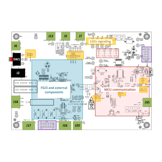
Figure 2. Location of key KITFS23LDOEVM components 4.4 KITFS23LDOEVM evaluation board This section describes the KITFS23LDOEVM evaluation board by explaining the features associated with each jumper and switch, giving information on hardware configuration to enable these features, and providing advice on LED signaling and test points available on the board. - Page 9 UM11879 NXP Semiconductors KITFS23LDOEVM evaluation board Figure 3. KITFS23LDOEVM default jumpers and switches configuration Table 1. Switches functions Position Function Description VIN_SEL Input voltage supply can come from battery (VIN_BAT) or from external power supply (VIN_PHX). HVIOx_CS Emulates a door switch as an example in cyclic sense configuration, by default for HVIO1, possible to change to HVIO2.
-
Page 10: Vin Selection (Sw1/J2/J6)
UM11879 NXP Semiconductors KITFS23LDOEVM evaluation board Table 2. Jumpers functions Position Function Description VIN_BAT Input voltage from battery via Jack connector (40 V max). V2_OUT Output for V2. VIN_PHX Input voltage from external power supply via Phoenix connector (40 V max). -
Page 11: V1, V2, V3 Connectors (J12/J5/J7)
UM11879 NXP Semiconductors KITFS23LDOEVM evaluation board 4.4.2 V1, V2, V3 connectors (J12/J5/J7) For FS2300, HVLDO1 can be configured to 3.3 V or 5.0 V, up to 100 mA with internal PMOS and up to 250 mA with external PNP. HVLDO2 can be configured to 3.3 V or 5.0 V, up to 100 mA current capability. -
Page 12: (J28/J29/J31/J32)
UM11879 NXP Semiconductors KITFS23LDOEVM evaluation board When VDD_MCU is supplied from onboard 5.0 V LDO (J37 in position 1-2), a distinct power supply must be connected to J35 Phoenix connector. This way, the MCU has a distinct power supply domain from FS23 device under evaluation. -
Page 13: Debug And Otp Configuration (J30/Sw10/Sw12)
UM11879 NXP Semiconductors KITFS23LDOEVM evaluation board Table 9. CAN and LIN connectors (J16/J20) Schematic label Signal name Description J16-1 CANH CAN bus high. J16-2 CANL CAN bus low. J16-3 Ground. J20-1 LIN bus. J20-2 Ground. 4.4.8 Debug and OTP configuration (J30/SW10/SW12) Debug mode is active when DEBUG pin (Pin 15) is set to 5 V. -
Page 14: High-Side Driver Connectors (J17/J18)
UM11879 NXP Semiconductors KITFS23LDOEVM evaluation board 4.4.9 High-side driver connectors (J17/J18) Each high-side driver (HSx) can be used to drive loads, or to perform cyclic sense when used in combination with a high-voltage input (WAKEx or HVIOx). High-side drivers are supplied by VSHS supply voltage. -
Page 15: Ext
The FS2300 can monitor an external regulator through VMON_EXT monitoring pin, accessible via J10-8 on the KITFS23LDOEVM. The regulator connected to VMON_EXT must be at least 1 V to be compatible with overvoltage and undervoltage monitoring thresholds. An external resistor bridge is used to divide the regulator voltage if higher than 1 V, and set the middle point to 1 V. - Page 16 UM11879 NXP Semiconductors KITFS23LDOEVM evaluation board Table 14. HSx configuration with corresponding resistor configuration Associated IO Cyclic sense Load/LED driver Load between J17-3 and J17-2 HVIO1 Populate R24 and R14 Load btw J17-1 and J17-2 HVIO2 Populate R24 and R31 Load between...
-
Page 17: Testing The Cyclic Sense Function With Onboard Switches
HVIO1, HVIO2, WAKE1, and WAKE2 pins can be configured for cyclic sensing when coupled with their corresponding HSx. The KITFS23LDOEVM provides a means to emulate door switches sensing with onboard switches, as an application example for the cyclic sense configuration. -
Page 18: Led Signaling
• Power: HVBUCK regulator output, HVLDOx regulator outputs • Power supply: VBAT, MCU supply • OTP control: Debug 5 V, OTP 8 V Figure 10. KITFS23LDOEVM LED signaling UM11879 All information provided in this document is subject to legal disclaimers. © 2023 NXP B.V. All rights reserved. -
Page 19: Test Points
Red: Test loop access for power supplies and CAN/LIN bus Black: Test loop access to GND Figure 11. KITFS23LDOEVM test points 4.4.14 Schematic layout and bill of materials The board layout and bill of materials for the KITFS23LDOEVM evaluation board are available at https:// www.nxp.com/KITFS23LDOEVM UM11879 All information provided in this document is subject to legal disclaimers. -
Page 20: Installing And Configuring Software Tools
5 Installing and configuring software tools 5.1 Flashing S32K144 MCU GUI firmware The KITFS23LDOEVM is delivered with the S32K144 firmware already flashed. 5.2 Installing the FS23 NXP GUI software package To install the FS2300 NXP GUI, first download or obtain the NXP GUI package, then follow the instructions below: 1. - Page 21 UM11879 NXP Semiconductors KITFS23LDOEVM evaluation board 4. On the License Agreement window, read the license information and click I Agree. Figure 15. GUI license agreement 5. In the Choose Components window, select the GUI components to install, then click Next.
- Page 22 UM11879 NXP Semiconductors KITFS23LDOEVM evaluation board Figure 17. GUI choose install location 7. In the Completing Setup window, select the following options: • Run NXP_GUI • Show Readme Then click Finish to complete the installation. Figure 18. Complete setup UM11879 All information provided in this document is subject to legal disclaimers.
-
Page 23: Launching The Fs23 Nxp Gui
5.3 Launching the FS23 NXP GUI When the KITFS23LDOEVM kit is set up and the GUI is installed, follow the steps below to launch the GUI: 1. Click the Windows icon (bottom left corner) and locate NXPGUI in the Windows All Apps bar, then click on the NXPGUI icon to launch the GUI. -
Page 24: Fs23 Nxp Gui
UM11879 NXP Semiconductors KITFS23LDOEVM evaluation board 6 FS23 NXP GUI This section gives guidance on use of the FS23 NXP GUI. 6.1 NXP GUI framework window The Framework window consists of the following sections: • Connection toolbar: Used to start communication with device, enter or exit Test/OTP modes, fix I... -
Page 25: Framework Settings Bar
UM11879 NXP Semiconductors KITFS23LDOEVM evaluation board 6.2 Framework settings bar The Framework settings section appears at the top left corner of the Framework window. It consists of four items: • File • View • Import/Export • Help Figure 23. Framework items 6.2.1 File menu item... -
Page 26: Import/Export Menu Item
UM11879 NXP Semiconductors KITFS23LDOEVM evaluation board Figure 26. View menu: Show • Naming Conventions: Allows the user to select Friendly or Register name display for OTP tool. Option enabled only when OTP tool is active. Figure 27. View menu: Naming Conventions ... -
Page 27: Help Menu Item
UM11879 NXP Semiconductors KITFS23LDOEVM evaluation board 6.2.4 Help menu item The Help menu item contains links to additional information, displays GUI and firmware version numbers, and a glossary for acronyms. Figure 29. Help menu • Documentation: Lists online NXP documentation related the FS2300 GUI. -
Page 28: Device Connection
UM11879 NXP Semiconductors KITFS23LDOEVM evaluation board 6.3.1 Device connection The device connection boxes appear first in the Connection toolbar menu. Figure 31. Device connection When the S32K144 MCU is not connected through the USB port, the State indicator in the USB and Status bar shows NOT DETECTED, the FS2300 header text appears red, and the Start button is not available. -
Page 29: Watchdog Management
UM11879 NXP Semiconductors KITFS23LDOEVM evaluation board 1. Start the FS23 NXP GUI in I C mode and connect the KITFS23LDOEVM to the GUI by following the procedure in Section 7.2. 2. Enter Test mode to be able to write into the Mirror registers. See Section 7.3.2. -
Page 30: Watchdog Enablement And Configuration On Sbc Side
UM11879 NXP Semiconductors KITFS23LDOEVM evaluation board 6.3.3.1 Watchdog enablement and configuration on SBC side On the FS2300 side, when the part is QM, Watchdog disablement is possible by OTP. Watchdog monitoring default configuration is done via SPI/I C via ACCESS tool. -
Page 31: Watchdog Configuration On Mcu Side
UM11879 NXP Semiconductors KITFS23LDOEVM evaluation board 6.3.3.2 Watchdog configuration on MCU side On the S32K144 MCU side, actions are configured with the Watchdog management boxes in the Connection toolbar menu. Figure 39. Enable Watchdog Refresh The mechanism is fully operative when both SBC and MCU actions are enabled and have matching configurations. -
Page 32: Tools Access Bar
UM11879 NXP Semiconductors KITFS23LDOEVM evaluation board 6.5 Tools access bar The Tools access bar appears in a vertical row along the left side of the Framework window. The bar provides access to tools that implement various GUI functions. The Tools access bar consists of nine items: •... -
Page 33: Otp
UM11879 NXP Semiconductors KITFS23LDOEVM evaluation board 6.5.2 OTP The OTP tool is used to enter an OTP configuration. The OTP configuration can be saved as a CFG file or exported as a TBB file: • The CFG file is used by the GUI to log all of the configuration information. The CFG file can be used to save an OTP configuration or load Mirror registers with the MIRROR tool in Debug mode. - Page 34 UM11879 NXP Semiconductors KITFS23LDOEVM evaluation board Figure 46. Power sequence configuration 6.5.2.1.2 Regulators tab The Regulators tab allows the user to set OTP Parameters for HVLDO1, HVLDO2, and HVLDO3. This tab displays a simplified diagram of the selected configuration as a visual crosscheck.
-
Page 35: Otp Details Window
UM11879 NXP Semiconductors KITFS23LDOEVM evaluation board Figure 48. Functional Safety tab 6.5.2.1.4 Program ID tab The Program ID tab displays the OTP ID. Only NXP users can create an OTP ID. Figure 49. Program ID tab 6.5.2.1.5 Calculator tab The Calculator tab is available for FS2320 version only. -
Page 36: Prog
UM11879 NXP Semiconductors KITFS23LDOEVM evaluation board 6.5.3 PROG The PROG tool provides access to device programming configuration and tools for the OTP burning process. Note: Use this tab cautiously, as a device can be programmed just twice. The programming tool is available only in Test mode. -
Page 37: Log Window
UM11879 NXP Semiconductors KITFS23LDOEVM evaluation board The Script editor window consists of four sections: • Log window • Script Commands • Script window and its Script bar • Script Results window Figure 53. SCRIPT tool 6.5.4.1 Log window The Log window lists events as they occur in real time when the script is executing. The Filter Messages box allows the user to limit log messages to certain events (Register Read, Register Write, Pin Read, Pin Write). - Page 38 UM11879 NXP Semiconductors KITFS23LDOEVM evaluation board Figure 54. Generate an initialization script example (INIT-Script) Note: HELP button in the Script bar gives information on Commands. Figure 55. Script command panel help All menu items work in a similar way. The example below shows a typical process using the Registers menu tab.
-
Page 39: Script Commands Window
UM11879 NXP Semiconductors KITFS23LDOEVM evaluation board Figure 56. Using the SCRIPT tool 6.5.4.3 Script Commands window The Script Commands window is the area where existing script files can be loaded in Test mode only and where script commands are entered, edited, and executed. -
Page 40: Mirror
UM11879 NXP Semiconductors KITFS23LDOEVM evaluation board 6.5.5 MIRROR The MIRROR tool provides access to all Mirror registers. Mirror registers are an emulation of OTP registers. Mirror registers can be read/written multiple times, whereas OTP registers can be burned once. In case of a power-on reset, the Mirror registers are reset to the default OTP configuration (empty if OTP sectors are not burned). -
Page 41: Registermap
UM11879 NXP Semiconductors KITFS23LDOEVM evaluation board The tab content contains 11 tabs: • RegisterMap • INIT Safety • WatchDog • DiagSafety • Main Tab • Regulators • Interrupts • AMUX • General I/Os • Physical Layers • CRC Calculator 6.5.6.1 Register map The Register Map tab allows the user to read or write the FS2300 SPI/I C registers, bit per bit. - Page 42 UM11879 NXP Semiconductors KITFS23LDOEVM evaluation board Figure 62. Registers Content window 6.5.6.1.2 Accessing one register content using Read and Write buttons In the Registers Content window, the user can read and/or write the FS2300 SPI/I C registers using the Read and Write buttons.
- Page 43 UM11879 NXP Semiconductors KITFS23LDOEVM evaluation board Figure 64. Bit-Map Dialog 6.5.6.1.4 Modifying multiple registers using the lower Read/Write/Reset bar In the Registers Content window, the user can read, write, and/or reset multiple FS2300 SPI/I C registers at a time using the lower Read/Write/Reset bar.
-
Page 44: Init Safety
UM11879 NXP Semiconductors KITFS23LDOEVM evaluation board 6.5.6.2 INIT Safety The INIT Safety tab allows the user to read or write the parameters related to the safety functions initialization and safety behavior configuration. Figure 66. INIT Safety tab • Fault Impact: To choose safety pin assertion response to each fault source. -
Page 45: Diagsafety
UM11879 NXP Semiconductors KITFS23LDOEVM evaluation board Figure 68. Watchdog tab 6.5.6.4 DiagSafety The DiagSafety tab allows the user to carry out the safety diagnosis by reading or clearing the interrupt and status bits of safety pins and UV/OV monitoring bits. The DiagSafety tab also allows the user to launch ABIST and observe the ABIST status. -
Page 46: Main Tab
UM11879 NXP Semiconductors KITFS23LDOEVM evaluation board 6.5.6.5 Main Tab The Main Tab allows the user to monitor Events occurrence, to operate the Device States, and to configure FS2300 functions such as Timers, PWMs, or Long Duration Timer (LDT). • General Flags: To monitor occurrence of events on FS2300 functions. -
Page 47: Interrupts
UM11879 NXP Semiconductors KITFS23LDOEVM evaluation board Figure 71. Regulators tab 6.5.6.7 Interrupts The Interrupts tab is arranged as an Interrupt board with two thematic sub-menus displaying one Interrupt box per function: • Main Interrupt Configuration: To monitor the events related to FS2300 functional features such as... -
Page 48: Amux
UM11879 NXP Semiconductors KITFS23LDOEVM evaluation board Figure 73. Using Interrupts tab 6.5.6.8 AMUX The AMUX tab allows the user to measure voltage levels and temperature values of multiple key locations from onboard sensors. The AMUX feature uses one ADC to successively measure multiple points. The AMUX feature must be enabled beforehand by clicking Enable AMUX. -
Page 49: General I/Os
UM11879 NXP Semiconductors KITFS23LDOEVM evaluation board Figure 74. AMUX menu Measurement graphs can be edited using their editing bar, as shown in Figure Figure 75. Measurement graphs 6.5.6.9 General I/Os The General I/Os tab allows the user to control I/O levels, to configure Wake-Up/Interrupt features, and to operate the Cyclic Sense feature depending on I/Os desired configuration. -
Page 50: Physical Layers Menu
UM11879 NXP Semiconductors KITFS23LDOEVM evaluation board • I/O Wake-up Config: To set I/O Wake-Up parameters when the Wake-Up feature is enabled on I/O. • Cyclic Sense: To enable Cyclic Sense feature, to set Cyclic Sense parameters on I/Os and High-Side pins, and to operate the Cyclic Sensing by monitoring status. -
Page 51: Crc Calculator
UM11879 NXP Semiconductors KITFS23LDOEVM evaluation board 6.5.6.11 CRC Calculator The CRC Calculator is used to compute I C/SPI protocol CRC from an address and a data field value in hexadecimal format. The user enters the address field content and the data field content of the I C/SPI frame to be sent, and reads CRC result. -
Page 52: Can
UM11879 NXP Semiconductors KITFS23LDOEVM evaluation board Figure 79. MCU PINS tool 6.5.8 CAN The CAN tool provides a means to use the CAN transceiver on FS2300. The CAN tool allows the user to configure the CAN bus on the MCU side and send edited frames on the bus sporadically or periodically with a selectable repeat rate. -
Page 53: Lin
UM11879 NXP Semiconductors KITFS23LDOEVM evaluation board • CAN Frames Editing window: To edit the frames to be sent on the CAN bus (up to 64 bytes) with hexadecimal values. CAN frames can be imported and saved as CSV files. • CAN Log window: Displays exchanged frames. -
Page 54: Setting Up And Running The Kitfs23Ldoevm
7 Setting up and running the KITFS23LDOEVM This section gives guidance on how to set up and run the KITFS23LDOEVM evaluation board and GUI. The device has a high level of flexibility thanks to the parameter configuration available by using the OTP registers. -
Page 55: Operation Modes
Understanding these modes helps the user interact with the GUI properly. Note: When using the KITFS23LDOEVM for the first time, it is recommended the user start the device in Debug mode so the Watchdog function is not active. Indeed, the Watchdog must be configured in Debug mode before starting the device in Normal mode for the first time. -
Page 56: Debug Mode
UM11879 NXP Semiconductors KITFS23LDOEVM evaluation board Figure 83 gives an overview of the device modes and actions to do in the GUI or on the EVB to enter or exit modes. Test mode stays active for as long as nothing is written in TM_ENTRY register. Therefore, it is possible to be in Test mode and Normal mode at the same time. -
Page 57: Debug Mode Activation
UM11879 NXP Semiconductors KITFS23LDOEVM evaluation board Debug mode is helpful during software development if the device has those functions enabled by OTP. 7.3.1.2 Debug mode activation There are two ways to activate Debug mode: 7.3.1.2.1 With the GUI using mode selection in Connection toolbar (recommended) 1. -
Page 58: Test Mode Activation: Hardware And Software
UM11879 NXP Semiconductors KITFS23LDOEVM evaluation board Test mode requires DEBUG SELECT jumper ON, DEBUG = +8 V (Debug mode is therefore enabled when Test mode is enabled) and valid Test mode keys sent by SPI/I C. Permanently fusing all the data stored in Mirror registers to the OTP sectors necessitates an extra key command, available in the PROG tool. -
Page 59: Normal Mode
UM11879 NXP Semiconductors KITFS23LDOEVM evaluation board 7.3.3 Normal mode 7.3.3.1 Normal mode definition The Normal mode operation is used for final product test in automotive environment. Normal mode entry at power-on reset requires DEBUG SELECT jumper J30 = OFF and DEBUG = GND. -
Page 60: First-Start Procedure: Configure Watchdog As Infinite Time Out
This procedure is to be used as a first-start and allows the user to enter system-level Normal mode execution with the Watchdog configured with infinite timeout and window fully opened (equivalent to disabled). 1. Set up and connect the KITFS23LDOEVM to the GUI using Section 7.1 Section 7.2. -
Page 61: Otp And Mirror Registers
UM11879 NXP Semiconductors KITFS23LDOEVM evaluation board Figure 88. ACCESS tool Note: If FS0B and LIMP0 cannot be released after resetting the fault error counter, check that no interrupt is still pending and triggering FS0B or LIMP0 assertion. 7.6 OTP and Mirror registers The device incorporates one OTP block for configuration. -
Page 62: Operate Otp Emulation By Loading Configuration In The Mirror Registers
UM11879 NXP Semiconductors KITFS23LDOEVM evaluation board Device Mirror OTP fuse configuration register configuration C/SPI S1 - config S1 - config Primary CONFIG S1bis - config Images CONFIG aaa-050006 Figure 89. OTP block diagram At device start up, the content of the last-programmed sector is loaded into the Mirror registers. The Mirror registers content is accessible from the NXP GUI. -
Page 63: Modify The Mirror Registers With The Mirror Tool
UM11879 NXP Semiconductors KITFS23LDOEVM evaluation board 7.7.2 Modify the Mirror registers with the MIRROR tool To configure the Mirror registers, the MIRROR tool can be used to write/read directly into Mirror registers. See Section 6.5.5. This requires Test mode to be activated. - Page 64 UM11879 NXP Semiconductors KITFS23LDOEVM evaluation board The device is empty and capable of being burned if Sector 1 is set to 0 (blue). Once the sector is burned, the sector flag is set to 1 (orange). The figure to the right shows the Sector Flags status in the Programming interface for an empty part.
- Page 65 UM11879 NXP Semiconductors KITFS23LDOEVM evaluation board Figure 92. Programming procedure UM11879 All information provided in this document is subject to legal disclaimers. © 2023 NXP B.V. All rights reserved. User manual Rev. 2 — 25 September 2023 65 / 73...
-
Page 66: Save A Routine From Log Window Then Run It As A Script
UM11879 NXP Semiconductors KITFS23LDOEVM evaluation board 7.9 Save a routine from Log window then Run it as a Script The Log window shows the requests and answers transiting between the S32K144 MCU and the FS23 device. The commands are sent using I²C or SPI protocol depending on user’s choice. -
Page 67: Init Crc Computation
UM11879 NXP Semiconductors KITFS23LDOEVM evaluation board 7.10 INIT CRC computation This section gives guidance on how to compute INIT CRC. A specific tool for INIT CRC computation is available in the GUI. See Section 6.5.6.11. Procedure for INIT CRC computation 1. -
Page 68: Tbb Script Example
UM11879 NXP Semiconductors KITFS23LDOEVM evaluation board 7.11 TBB script example This TBB script, which corresponds to FS2300 HVBUCK ASIL B version, is given as an example code. //FS2300 - OTP Editor SET_REG:FS2300:OTP:M_MIRRORCMD:0x012C //file generated on jeu. juin 2 11:00:02 2022... -
Page 69: Legal Information
NXP Semiconductors. specifications with known limitations. Customer is responsible for the design In no event shall NXP Semiconductors be liable for any indirect, incidental, and operation of its applications and products throughout their lifecycles punitive, special or consequential damages (including - without limitation - to reduce the effect of these vulnerabilities on customer’s applications... - Page 70 UM11879 NXP Semiconductors KITFS23LDOEVM evaluation board Tables Tab. 1. Switches functions ..........9 Tab. 11. High-side driver connectors (J17/J18) .....14 Tab. 2. Jumpers functions ........... 10 Tab. 12. VDDIO selection jumper (J26) ......14 Tab. 3. VIN selection (SW1/J2/J6) ......10 Tab.
- Page 71 Wake pins configuration as global input Fig. 59. MIRROR tool ...........40 pins ..............17 Fig. 60. ACCESS tool ...........40 Fig. 10. KITFS23LDOEVM LED signaling ....18 Fig. 61. Register Map menu .........41 Fig. 11. KITFS23LDOEVM test points ......19 Fig. 62. Registers Content window ......42 Fig.
-
Page 72: Table Of Contents
Setting up and running the KITFS23LDOEVM ..........54 4.4.11.4 Setting VSUP as an input for WAKE1 pin (global) ............. 17 Setting up the KITFS23LDOEVM ....54 4.4.12 LED signaling ..........18 Connecting the KITFS23LDOEVM to the 4.4.13 Test points ............19 GUI ..............54... - Page 73 UM11879 NXP Semiconductors KITFS23LDOEVM evaluation board 7.7.1 Modify the Mirror registers with a TBB script ... 62 7.7.2 Modify the Mirror registers with the MIRROR tool ........... 63 Programming an OTP configuration ....63 Save a routine from Log window then Run it as a Script ............
Need help?
Do you have a question about the KITFS23LDOEVM and is the answer not in the manual?
Questions and answers