Table of Contents
Advertisement
Quick Links
UM11670
KITFS86SKTFRDMEM evaluation board
Rev. 1 — 5 November 2021
Document information
Information
Content
Keywords
FS8600, KITFS86SKTFRDMEM, KL25Z, I2C
Abstract
The KITFS86SKTFRDMEM provides flexibility to play with all the features of
the device and make measurements on the main part of the application.
User manual
Advertisement
Table of Contents

Subscribe to Our Youtube Channel
Related Manuals for NXP Semiconductors KITFS86SKTFRDMEM


Summary of Contents for NXP Semiconductors KITFS86SKTFRDMEM
- Page 1 Rev. 1 — 5 November 2021 User manual Document information Information Content Keywords FS8600, KITFS86SKTFRDMEM, KL25Z, I2C Abstract The KITFS86SKTFRDMEM provides flexibility to play with all the features of the device and make measurements on the main part of the application.
- Page 2 UM11670 NXP Semiconductors KITFS86SKTFRDMEM evaluation board Revision history Revision history Date Description 20211105 • Initial version UM11670 All information provided in this document is subject to legal disclaimers. © NXP B.V. 2021. All rights reserved. User manual Rev. 1 — 5 November 2021...
- Page 3 UM11670 NXP Semiconductors KITFS86SKTFRDMEM evaluation board Important notice NXP provides the enclosed product(s) under the following conditions: This evaluation kit is intended for use of ENGINEERING DEVELOPMENT OR EVALUATION PURPOSES ONLY. It is provided as a sample IC pre-soldered to a printed circuit board to make it easier to access inputs, outputs, and supply terminals.
-
Page 4: Introduction
Working with the KITFS86SKTFRDMEM requires the kit contents, additional hardware and a Windows PC workstation with installed software. 3.1 Kit contents • Assembled and tested KITFS86SKTFRDMEM connected to a FRDM-KL25Z in an anti- static bag • 3.0 ft USB-STD A to USB-B-mini cable •... -
Page 5: Additional Hardware
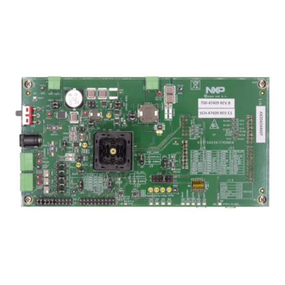
- latest version Getting to know the hardware The KITFS86SKTFRDMEM provides flexibility to play with all the features of the device and make measurements on the main part of the application. The KL25Z MCU Freedom board plugged on the board, combined with the NXP GUI software allows access to the registers in read and write mode. -
Page 6: Kitfs86Sktfrdmem Features
• Support OTP fuse capabilities • Voltage monitoring jumper setting 4.3 Schematic, board layout and bill of materials The schematic, board layout and bill of materials for the KITFS86SKTFRDMEM evaluation board are available at http://www.nxp.com/KITFS86SKTFRDMEM. 4.3.1 VMON board configuration The VMONx configuration is highly dependent on the use case. This kit is delivered with a default configuration. - Page 7 UM11670 NXP Semiconductors KITFS86SKTFRDMEM evaluation board selected so that VMON5_RES and VMON6_RES would receive 0.8 V if VMONX_RES voltage inputs were respectively 3.3 V and 5.0 V. Figure 2 shows the corresponding part of the schematic. VMON5_3V3 37.4 kΩ VMON5_RES 12 kΩ...
-
Page 8: Vpre Compensation Network
UM11670 NXP Semiconductors KITFS86SKTFRDMEM evaluation board VMON7 VMON7_RES 0 Ω 20 kΩ VMON_08V 5.1 kΩ 3 2 1 Jumper (Default) = 1-2 Short HDR 1X3 VMON8 VMON8_RES 10 kΩ 20 kΩ VMON_08V 5.1 kΩ 3 2 1 Jumper (Default) = 1-2 Short... -
Page 9: Battery Switch
UM11670 NXP Semiconductors KITFS86SKTFRDMEM evaluation board Table 1. Compensation network ...continued Components VPRE 455 kHz VPRE 2.22 MHz Ccomp1/Ccomp2 7.5 nF 1.8 nF Rcomp1/Rcomp2 4.7 kΩ 5.6 kΩ LPRE From 4.7 µH to 10 µH From 1.5 µH to 4.7 µH 4.3.3 Battery switch... -
Page 10: I2C
UM11670 NXP Semiconductors KITFS86SKTFRDMEM evaluation board VSUP 10 kΩ BAT_SW MMSZ5240BT1G 10 kΩ VBOS BC858B PMOS_G 150 kΩ 10 kΩ BC846A 10 kΩ VBOS MMBT2369ALT1G 0 Ω 10 kΩ 10 kΩ BAT_SW 0.01 µF BC846A 10 kΩ 10 nF R157 2 kΩ... -
Page 11: Vmon0_I2C
UM11670 NXP Semiconductors KITFS86SKTFRDMEM evaluation board 4.3.5 VMON0_I2C VMON0_I2C pin is powered through VDDI2C net and is used to supply internal buffers and I C communication. This supply is monitored through this pin depending on the OTP configuration. The monitoring voltage needs to be selected by the OTP. -
Page 12: Kit Featured Components
UM11670 NXP Semiconductors KITFS86SKTFRDMEM evaluation board P3V3_KL25Z 1-2: 425 kHz 3-2: 2.44 kHz R149 R148 R150 100 kΩ DEFAULT (1-2) 47 kΩ 0 Ω 0.1 µF HDR 1X3 425 kHz 2.44 MHz R151 0 Ω, DNP LTC6900CS5#PBF aaa-044211 Figure 11. FIN oscillator 4.4 Kit featured components... -
Page 13: Led Signaling
UM11670 NXP Semiconductors KITFS86SKTFRDMEM evaluation board Table 2. Evaluation board featured components location ...continued Number Description VBAT three position switch • Left position: board supplied by Jack connector • Middle position: board not supplied • Right position: board supplied by Phoenix connector... -
Page 14: Connectors
UM11670 NXP Semiconductors KITFS86SKTFRDMEM evaluation board Table 3. Evaluation board LED signaling description ...continued Label Name Color Description FS0B FS0B asserted (logic level = 0) INTB INTB asserted (logic level = 0) PGOOD Green PGOOD released VBAT Green VBAT On VPRE... -
Page 15: Debug Connector (J25)
UM11670 NXP Semiconductors KITFS86SKTFRDMEM evaluation board Table 5. LDO1/LDO2 connector (J21) ...continued Schematic label Signal name Description J21-3 Ground Table 6. VBOOST/BUCK connector (J22) Schematic label Signal name Description J22-1 VBOOST VBOOST output J22-2 BUCK BUCK power supply output J22-3 Ground Table 7. VPRE connector (J23) -
Page 16: Voltage Monitoring Connector (J26)
UM11670 NXP Semiconductors KITFS86SKTFRDMEM evaluation board 4.4.2.4 Voltage monitoring connector (J26) Table 9. Voltage monitoring connector (J26) Schematic label Signal name Description J26-1 VPRE VPRE power supply output J26-2 VMON8 Voltage monitoring input n°8 J26-3 VBOOST VBOOST output J26-4 VMON7 Voltage monitoring input n°7... - Page 17 UM11670 NXP Semiconductors KITFS86SKTFRDMEM evaluation board Table 11. I C connector (J2) ...continued Schematic label Signal name Description J2-19 n.c. not connected J2-20 I2C_SCL_MCU C Serial Clock line Table 12. ADC connector (J10) Schematic label Signal name Description J10-1 VBOOST_ADC BOOST power supply to KL25Z ADC...
-
Page 18: Test Points
UM11670 NXP Semiconductors KITFS86SKTFRDMEM evaluation board 4.4.3 Test points Figure 15 shows test points that provide access to various signals to and from the boards. Figure 15. Evaluation board test points Table 15. Evaluation board test points description Test point name Signal name... -
Page 19: Jumpers
UM11670 NXP Semiconductors KITFS86SKTFRDMEM evaluation board 4.4.4 Jumpers Figure 16 shows jumper locations for board configuration. Figure 16. Evaluation board jumpers location (with default position) Table 16. Evaluation board jumpers description Name Function Pin number Jumper/pin function BAT_SW shunt 1−2 Bypass BAT_SW protection 3−4... -
Page 20: Switches
UM11670 NXP Semiconductors KITFS86SKTFRDMEM evaluation board Table 16. Evaluation board jumpers description ...continued Name Function Pin number Jumper/pin function VMON5_RES input 1–2 VMON5_RES pin tied to VMON_08V (fixed 0.8 V) selection 2–3 VMON5_RES pin tied to configured regulator (through J25) VMON8_RES input 1–2... -
Page 21: Configuring The Hardware For Startup
UM11670 NXP Semiconductors KITFS86SKTFRDMEM evaluation board Table 18. SW2 description ...continued Position Function Description MIDDLE VBAT Off Board not supplied BOTTOM VBAT On VBAT from J29 Table 19. SW3 description Position Function Description OTP mode On FS8600 can be emulated or burnt by OTP... - Page 22 (DBG = 4.5 V) close (OTP mode ON) 2. Connect the Windows PC USB port to the KITFS86SKTFRDMEM development board using the provided USB 2.0 cable. 3. Set the DC power supply to 12 V and current limit to 1.0 A. With power turned Off, attach the DC power supply positive and negative output to VBAT Phoenix connector (J6).
-
Page 23: References
NXP Semiconductors KITFS86SKTFRDMEM evaluation board References KITFS86SKTFRDMEM — detailed information on this board, including documentation, downloads, and software and tools http://www.nxp.com/KITFS86SKTFRDMEM FS86 — detailed information on FS8600, Safety System Basis Chip For Domain Controller, Fit For ASIL B and D http://www.nxp.com/FS86... -
Page 24: Legal Information
NXP Semiconductors. In no event shall NXP product remains with customer. In no event shall NXP Semiconductors, its... - Page 25 UM11670 NXP Semiconductors KITFS86SKTFRDMEM evaluation board Tables Tab. 1. Compensation network ........8 Tab. 11. I2C connector (J2) .......... 16 Tab. 2. Evaluation board featured components Tab. 12. ADC connector (J10) ........17 location ............12 Tab. 13. KL25Z supply connector (J14) ......17 Tab.
-
Page 26: Table Of Contents
Additional hardware ........... 5 Windows PC workstation ........5 Software .............5 Getting to know the hardware ......5 Kit overview ............5 KITFS86SKTFRDMEM features ......6 Schematic, board layout and bill of materials ............6 4.3.1 VMON board configuration ........ 6 4.3.2...
Need help?
Do you have a question about the KITFS86SKTFRDMEM and is the answer not in the manual?
Questions and answers