Table of Contents
Advertisement
Quick Links
Advertisement
Table of Contents

Subscribe to Our Youtube Channel
Related Manuals for NXP Semiconductors FS5600


Summary of Contents for NXP Semiconductors FS5600
- Page 1 UM11642 KITFS5600SKTEVM evaluation board Rev. 1 — 23 July 2021 User manual Document information Information Content Keywords FS5600, controller, FET Abstract The KITFS5600SKTEVM is a hardware evaluation tool that allows performance test of the FS5600.
- Page 2 UM11642 NXP Semiconductors KITFS5600SKTEVM evaluation board Revision history Revision history Date Description 20210723 • Initial version UM11642 All information provided in this document is subject to legal disclaimers. © NXP B.V. 2021. All rights reserved. User manual Rev. 1 — 23 July 2021...
- Page 3 UM11642 NXP Semiconductors KITFS5600SKTEVM evaluation board Important notice NXP provides the enclosed product(s) under the following conditions: This evaluation kit is intended for use of ENGINEERING DEVELOPMENT OR EVALUATION PURPOSES ONLY. It is provided as a sample IC pre-soldered to a printed circuit board to make it easier to access inputs, outputs, and supply terminals.
-
Page 4: Introduction
KITFS5600SKTEVM evaluation board Introduction The FS5600 integrates a 36 V DC-DC controller with external FETs and a 36 V DC- DC converter with internal FETs. In addition, it offers functional safety features such as independent voltage monitors, windowed watchdog timer, I/O monitoring via ERRMON and FCCU and built-in self-test. -
Page 5: Windows Pc Workstation
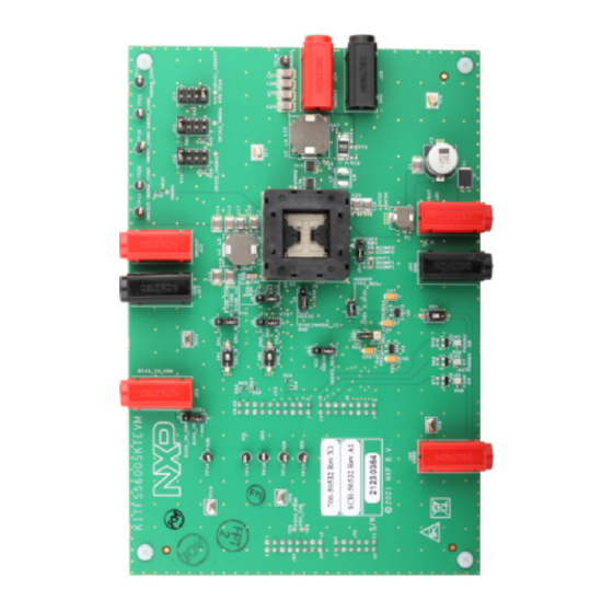
4.1 Kit overview The KITFS5600SKTEVM is a hardware evaluation tool that allows performance test and OTP programming of the FS5600. An Emulation mode is possible to test different OTP configurations as needed. Different inductors and MOSFETs are included in the kit to allow the user to try different switching frequencies. - Page 6 4. BIAS_IN input 5. Debug voltage input 6. EN1 and EN2 switches 7. GPIO1/2/3 option selection 8. 32-pin QFN socket for inserting the FS5600 Figure 1. Evaluation board featured component locations UM11642 All information provided in this document is subject to legal disclaimers.
-
Page 7: Jumpers
UM11642 NXP Semiconductors KITFS5600SKTEVM evaluation board 4.2.1 Jumpers Figure 2. Evaluation board jumper/switch locations Table 1. Evaluation board jumper/switch descriptions Name Default Description 2-3 shorted Controls EN1 source • 1-2 shorted → From Freedom board • 2-3 shorted → From onboard switch 2−3 shorted... -
Page 8: Schematic, Board Layout And Bill Of Materials
UM11642 NXP Semiconductors KITFS5600SKTEVM evaluation board Table 1. Evaluation board jumper/switch descriptions ...continued Name Default Description 7−8 shorted GPIO1 selection • 1-2 → Floating • 3-4 → GPO1 • 5-6 → ERRMON1 • 7-8 → VDDOTP (for debug and development) 1−2 shorted BIAS_IN selection •... - Page 9 UM11642 NXP Semiconductors KITFS5600SKTEVM evaluation board 1. Press the RST push button on the Freedom board and connect the USB cable into the SDA port (J5) on the Freedom board. 2. If a new “BOOTLOADER” device appears on the left pane of the File explorer: a.
-
Page 10: Configuring The Hardware For Startup
UM11642 NXP Semiconductors KITFS5600SKTEVM evaluation board 5. Freedom board Firmware is successfully loaded. Disconnect and reconnect the USB cable into the USB port. Open the previously installed NXPGUI. The “Start” button on the top-left corner must be activated. 6. If only the NXPGUI firmware needs to be updated, then start from step 4 above. The PC detects FRDM_K82FD. - Page 11 UM11642 NXP Semiconductors KITFS5600SKTEVM evaluation board 5. A configuration window is displayed. Select the kit type and the device silicon version, and then click OK. 6. Click Start to enable the connection to the device. Once the device is connected properly, the “Start”...
-
Page 12: Using The Kitfs5600Sktevm Evaluation Board
3. Apply 12 V at J92. 4. Apply EN1 or EN2 = High. 5. The state machine of FS5600 stops in a debug state to allow the user to configure the mirror registers. The mirror registers can be configured in this state using the GUI either by running a script, or individually modifying them. -
Page 13: References
References KITFS5600SKTEVM — detailed information on this board, including documentation, downloads, and software and tools http://www.nxp.com/KITFS5600SKTEVM FS5600 — product information on FS5600, Automotive Dual Buck Regulator and Controller with Voltage Monitors and Watchdog Timer http://www.nxp.com/FS5600 UM11642 All information provided in this document is subject to legal disclaimers. -
Page 14: Legal Information
NXP Semiconductors. In no event shall NXP product remains with customer. In no event shall NXP Semiconductors, its... - Page 15 UM11642 NXP Semiconductors KITFS5600SKTEVM evaluation board Tables Tab. 1. Evaluation board jumper/switch descriptions ............7 Figures Fig. 1. Evaluation board featured component Fig. 2. Evaluation board jumper/switch locations ..7 locations ............6 Fig. 3. Typical initial configuration ......10 UM11642 All information provided in this document is subject to legal disclaimers.
-
Page 16: Table Of Contents
UM11642 NXP Semiconductors KITFS5600SKTEVM evaluation board Contents Introduction ............4 Finding kit resources and information on the NXP web site ..........4 Getting ready ............4 Kit contents ............4 Additional hardware ........... 4 Windows PC workstation ........5 Software .............5 Getting to know the hardware ......5 Kit overview ............
Need help?
Do you have a question about the FS5600 and is the answer not in the manual?
Questions and answers