Table of Contents
Advertisement
Quick Links
UM11723
KITPF5200FRDMEVM evaluation board
Rev. 1 — 8 December 2021
Document information
Information
Content
Keywords
PF5200, FRDM-KL25Z, PF200 NXP GUI, PMIC, mirror register, One-Time
Programming, Try Before Buy
Abstract
The KITPF5200FRDMEVM evaluation board user guide is intended for the
engineers involved in the evaluation, design, implementation, and validation
of PF5200, Fail-safe system basis chips with multiple SMPS. The main
purpose of this board is to run performance test. For device programming,
use KITPF5200SKTEVM socket board.
User manual
Advertisement
Table of Contents

Related Manuals for NXP Semiconductors UM11723


Summary of Contents for NXP Semiconductors UM11723
- Page 1 UM11723 KITPF5200FRDMEVM evaluation board Rev. 1 — 8 December 2021 User manual Document information Information Content Keywords PF5200, FRDM-KL25Z, PF200 NXP GUI, PMIC, mirror register, One-Time Programming, Try Before Buy Abstract The KITPF5200FRDMEVM evaluation board user guide is intended for the engineers involved in the evaluation, design, implementation, and validation of PF5200, Fail-safe system basis chips with multiple SMPS.
- Page 2 NXP Semiconductors KITPF5200FRDMEVM evaluation board Revision history Table 1. Revision history Revision Date Description UM11723 v.1 20211208 Initial release UM11723 All information provided in this document is subject to legal disclaimers. © NXP B.V. 2021. All rights reserved. User manual Rev. 1 — 8 December 2021...
- Page 3 UM11723 NXP Semiconductors KITPF5200FRDMEVM evaluation board Important notice NXP provides the enclosed product(s) under the following conditions: This evaluation kit is intended for use of ENGINEERING DEVELOPMENT OR EVALUATION PURPOSES ONLY. It is provided as a sample IC pre-soldered to a printed circuit board to make it easier to access inputs, outputs, and supply terminals.
-
Page 4: Introduction
Finding kit resources and information on the NXP web site NXP Semiconductors provides online resources for this evaluation board and its supported device(s) on http://www.nxp.com. The information page for KITPF5200FRDMEVM evaluation board is at http:// www.nxp.com/KITPF5200FRDMEVM. -
Page 5: Windows Pc Workstation
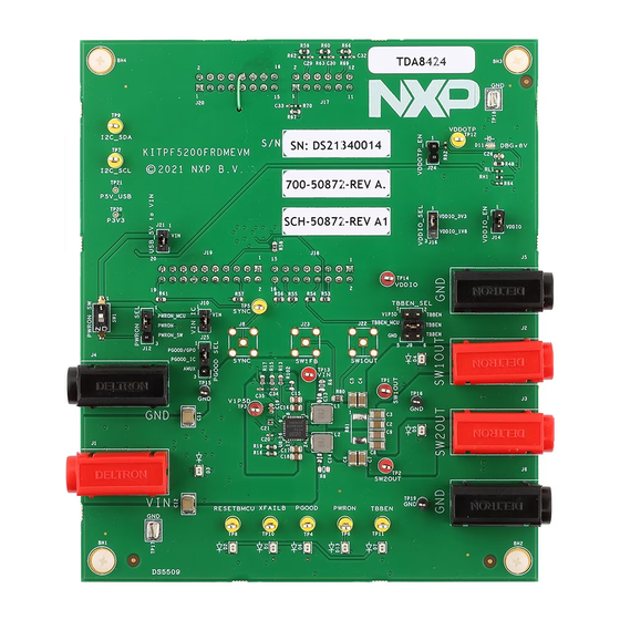
UM11723 NXP Semiconductors KITPF5200FRDMEVM evaluation board • Power supply with a range of 3.3 V to 5.0 V. Current limit depends of the use case, but a 4.0 A current limit supports all use cases 3.3 Windows PC workstation This evaluation board requires a Windows PC workstation. - Page 6 UM11723 NXP Semiconductors KITPF5200FRDMEVM evaluation board Figure 1. Evaluation board featured component locations Table 2. Jumper or switch functions Position Function Description J1 / J4 Input voltage (3.3 V min / 5.5 V max) J2 / J5 SW1OUT Output for SW1 J3 / J6...
-
Page 7: Vin Connectors
UM11723 NXP Semiconductors KITPF5200FRDMEVM evaluation board Table 2. Jumper or switch functions ...continued Position Function Description PGOOD_SEL PGOOD setting either PGGO/GPO or output of temperature junction analog voltage 4.3.1 VIN connectors Nominal VIN voltage is 3.3 V minimum / 5.5 V maximum. -
Page 8: Vin_Ic Jumper (J10)
UM11723 NXP Semiconductors KITPF5200FRDMEVM evaluation board 4.3.5 VIN_IC jumper (J10) This jumper selects the VIN power source. The main purpose is to enable VIN current measurements. Table 7. VIN_IC jumper (J10) Schematic label Signal name Description J10-1 Connected to VIN power input power supply... -
Page 9: Led Signaling
UM11723 NXP Semiconductors KITPF5200FRDMEVM evaluation board 4.3.10 LED signaling The LED signaling displays the state of the following signals: • Signals: PWRON, TBBEN, PGOOD, RESETBMCU and XFAIL • Regulators: SW1OUT and SW2OUT, LEDs light above 0.6 V • Power supply: VIN... -
Page 10: Schematic, Board Layout And Bill Of Materials
UM11723 NXP Semiconductors KITPF5200FRDMEVM evaluation board SW1OUT SW2OUT V1P5D PGOOD SYNC PWRON I2C_SCL RESETBMCU I2C_SDA XFAILB TP10 TBBEN VDDOTP TP11 TP12 VDDIO VDDIO TP13 TP14 TP15 TP16 TP17 TP18 TP19 aaa-044591 Figure 3. Test points 4.4 Schematic, board layout and bill of materials The schematic, board layout and bill of materials for the KITPF5200FRDMEVM evaluation board are available at http://www.nxp.com/KITPF5200FRDMEVM. -
Page 11: Flashing The Frdm-Kl25Z Firmware - Windows 10
UM11723 NXP Semiconductors KITPF5200FRDMEVM evaluation board 3. Disconnect and reconnect the USB cable into the SDA port. • This time without pressing the RST push-button, the FRDM_KL25Z device should appear on the left pane of the File explorer as shown in the following figure. -
Page 12: Pf52 Nxp Gui
UM11723 NXP Semiconductors KITPF5200FRDMEVM evaluation board 4. Disconnect and reconnect the USB cable into the SDA port. • This time without pressing the RST push-button, the FRDM_KL25Z device should appear on the left pane of the File explorer as shown in the following figure. - Page 13 UM11723 NXP Semiconductors KITPF5200FRDMEVM evaluation board 3. Click Next when the initial application setup window appears. UM11723 All information provided in this document is subject to legal disclaimers. © NXP B.V. 2021. All rights reserved. User manual Rev. 1 — 8 December 2021...
- Page 14 UM11723 NXP Semiconductors KITPF5200FRDMEVM evaluation board 4. On the License Agreement window, read the license information and click I Agree. UM11723 All information provided in this document is subject to legal disclaimers. © NXP B.V. 2021. All rights reserved. User manual Rev.
- Page 15 UM11723 NXP Semiconductors KITPF5200FRDMEVM evaluation board 5. In the Choose Components window, select the GUI components you want to install. Then click Next. UM11723 All information provided in this document is subject to legal disclaimers. © NXP B.V. 2021. All rights reserved.
- Page 16 UM11723 NXP Semiconductors KITPF5200FRDMEVM evaluation board 6. In the Choose Install Location window, choose the folder where you want the GUI installed. UM11723 All information provided in this document is subject to legal disclaimers. © NXP B.V. 2021. All rights reserved.
-
Page 17: Launching The Pf52 Nxp Gui
UM11723 NXP Semiconductors KITPF5200FRDMEVM evaluation board 7. In the completing setup window, select the following options: • Run NXP_GUI • Show Readme Click Finish to complete the installation. 8. When the installation is completed, the GUI opens automatically. Proceed to Step 2 in Section 5.2.2 "Launching the PF52 NXP... -
Page 18: The Framework Window
UM11723 NXP Semiconductors KITPF5200FRDMEVM evaluation board Selection window can also be disabled through the File main menu item. When you finish selecting the settings, click OK. 3. The Framework window opens as shown below: 5.2.3 The Framework window The Framework window consist of the following sections: UM11723 All information provided in this document is subject to legal disclaimers. -
Page 19: Framework Settings
UM11723 NXP Semiconductors KITPF5200FRDMEVM evaluation board • Device manager: used to start communication with device, enter or exit test mode, enable I C CRC and I C secure access, enable watchdog. • Framework settings: manages file import/export and framework configuration. - Page 20 UM11723 NXP Semiconductors KITPF5200FRDMEVM evaluation board 5.2.3.1.1 File menu item Load or save a configuration or exit the application. Load and Save are only enabled when OTP tool tab is active. • Display GUI kit selection at start: when starting the GUI, allows you to enable/disable the kit selection window.
- Page 21 UM11723 NXP Semiconductors KITPF5200FRDMEVM evaluation board • Naming conventions: selects Friendly or Register name display for OTP tool. Option enabled only when OTP tool is active. The naming convention options are: – Friendly: causes register names to be displayed as user-friendly names throughout the OTP tool.
- Page 22 UM11723 NXP Semiconductors KITPF5200FRDMEVM evaluation board • HEX: outputs the script in HEX format. A drop-down menu allows you to select the type of HEX format to be exported. – I-HEX: exports as an Intel Hex script file. – S-HEX: exports as a Simple Hex script file.
-
Page 23: Device Manager
UM11723 NXP Semiconductors KITPF5200FRDMEVM evaluation board 5.2.3.2 Device manager The Device Manger menu is located directly below the framework settings menu in the top left corner of the framework window (Figure Note: The Device manager does not display if the Connection toolbar is not selected in the Frameworks setting →... - Page 24 UM11723 NXP Semiconductors KITPF5200FRDMEVM evaluation board Click the Start button to start communication with the PF5200. At this point, the State indicator displays CONNECTED and PF5200 header text changes from red to green. Usually, when connected, the next step is to load a script that is written to the Mirror register.
-
Page 25: Tools Access Bar
UM11723 NXP Semiconductors KITPF5200FRDMEVM evaluation board 5.2.3.3 Tools access bar The Tools access bar appears in a vertical row along the left side of the framework window. It provides access to tools that implement various GUI functions. The tool access bar consists of seven items: •... - Page 26 UM11723 NXP Semiconductors KITPF5200FRDMEVM evaluation board 5.2.3.3.2 Script The script editor allows you to create script sequences or to send existing sequences to the device. You can read/write individually to a register, to a digital pin, or to an analog pin. You can also emulate an OTP configuration with this tool. The Script tool is accessible from Tool access bar.
- Page 27 UM11723 NXP Semiconductors KITPF5200FRDMEVM evaluation board • Digital pins: enters the script command to read the value of the selected digital pin. • Analog pins: enters the script command to read the value of the selected analog pin. • Registers: enters the script command to read or write to functional and OTP functional registers.
- Page 28 UM11723 NXP Semiconductors KITPF5200FRDMEVM evaluation board The Script command window is the area where existing script files can be loaded and where script commands are entered, edited, and executed. The menu bar at the bottom of the window contains the following six buttons: •...
- Page 29 UM11723 NXP Semiconductors KITPF5200FRDMEVM evaluation board There are two different tbb-mode procedures, depending on whether or not the OTP fuses have already been burned. Working with a part whose OTP fuses have not yet been burned: 1. Before performing a read or write, be sure you are in tbb-mode. To do so, select tbb- mode in the Device Manager menu and click Apply.
- Page 30 UM11723 NXP Semiconductors KITPF5200FRDMEVM evaluation board 4. Click IO PINS button in the Tools access bar. When the IO PINS window appears, set TBBEN high. If TBBEN has already been set high by the MCU, do nothing. 5. Return to the Mirror tool and Read/Write the mirror registers as you require.
- Page 31 UM11723 NXP Semiconductors KITPF5200FRDMEVM evaluation board Figure 6. OTP tool main panel sections UM11723 All information provided in this document is subject to legal disclaimers. © NXP B.V. 2021. All rights reserved. User manual Rev. 1 — 8 December 2021 31 / 51...
- Page 32 UM11723 NXP Semiconductors KITPF5200FRDMEVM evaluation board • OTP parameter setting section: this section is organized into four tabs. – Configuration tab: provides a means of setting miscellaneous PF5200 configuration parameters. The system configuration tab displays a different window, depending on whether a QM device or an ASIL B device has been selected in the Program Details panel.
- Page 33 UM11723 NXP Semiconductors KITPF5200FRDMEVM evaluation board the following figure, some fields are unavailable when OTP_PWRDN_MODE is set to sequential instead group. The Sequence diagram graph displays the power-up/power-down sequence. The x-axis of the Sequence diagram can be set to either time mode (displays the sequence in increments of time) or slot mode (displays the sequence in terms of the assigned sequence slots).
- Page 34 UM11723 NXP Semiconductors KITPF5200FRDMEVM evaluation board mode only, the OTP_SW_MODE setting in the SW miscellaneous window cannot be changed. – Program ID tab: displays the OTP ID. Only NXP users can create a new OTP ID. UM11723 All information provided in this document is subject to legal disclaimers.
- Page 35 UM11723 NXP Semiconductors KITPF5200FRDMEVM evaluation board • OTP Details section: collects and stores information about the customer and OTP version. All the information entered in this section is retained as part of the .cfg and TBB file. – The Custom Details window collects information related to the customer.
-
Page 36: Tab Content
UM11723 NXP Semiconductors KITPF5200FRDMEVM evaluation board The IO PINS panel consists of three sections: • Log window: maintains a running log of events initiated during the current session. A drop-down menu in the upper left allows the log to be filtered by register read, register write, pin read, and pin write. - Page 37 UM11723 NXP Semiconductors KITPF5200FRDMEVM evaluation board • OTP functional: OTP functional registers access (OTP mirrors register map) In each submenu, registers are organized by categories in the panel on the left. The PF5200 has two types of registers. Read-only registers (for example, ID registers) appear with a Read button only.
- Page 38 UM11723 NXP Semiconductors KITPF5200FRDMEVM evaluation board The SW regulators tab gives the main setting of each switch and monitoring configuration. 5.2.3.4.3 Sequence The Sequence tab sets up the power up/power down sequence and the switcher slot assignments for the device. The tab has three sections: •...
- Page 39 UM11723 NXP Semiconductors KITPF5200FRDMEVM evaluation board 5.2.3.4.5 PMIC config The PMIC config tab allows you to manage values related to various functions such as Watchdog, Thermal Monitoring, etc. The PMIC config tab contains the following windows: • AMUX: sets values for AMUX_SEL and AMUX_EN •...
- Page 40 UM11723 NXP Semiconductors KITPF5200FRDMEVM evaluation board In ASIL-B, an exhaustive list of bits is available only in the I C functional registers. 5.2.3.4.7 Interrupts The Interrupts tag displays interrupts by category and allows you to clear or mask selected interrupts.
-
Page 41: Setting Up And Running The Kitpf5200Frdmevm
UM11723 NXP Semiconductors KITPF5200FRDMEVM evaluation board 5.2.3.4.9 PMIC ID The PMIC tab provides basic information regarding the device. It contains three sections: • Device ID: shows the device family and indicates whether the part is trimmed ASIL B or QM. - Page 42 UM11723 NXP Semiconductors KITPF5200FRDMEVM evaluation board 1. Make sure that the board has the jumper’s configured in their default positions as shown in Figure 7. The default configuration enables the board to be fully controlled by the FRDM-KL25Z and the GUI.
-
Page 43: Connecting The Pf5200 To The Gui
UM11723 NXP Semiconductors KITPF5200FRDMEVM evaluation board 6.2 Connecting the PF5200 to the GUI The procedure for connecting the PF5200 to the GUI is as follows: 1. Click the Windows icon at the bottom left of the screen and select NXPGUI icon to open the GUI. -
Page 44: Programing A Tbb Operation
UM11723 NXP Semiconductors KITPF5200FRDMEVM evaluation board PF5200. If the USB cable is not plugged in, the State message displays "NOT DETECTED". 4. To establish communication between the FRDM- KL25Z and the PF5200 and allow the GUI to take control, click Start in the upper left corner. - Page 45 UM11723 NXP Semiconductors KITPF5200FRDMEVM evaluation board Window, click OPEN to load the TBB script file into the Script Command Window. Note that the script file must have a “PF5200” prefix. You can also copy and paste the script file in Section 6.5 "OTP script example"...
-
Page 46: Programming An Otp Operation
UM11723 NXP Semiconductors KITPF5200FRDMEVM evaluation board 6.4 Programming an OTP operation The PROG tool (Section 5.2.3.3.3 "Prog") is used to execute the OTP script and burn the PF5200 fuses. The OTP script can be the same one created and tested in Section 6.3... -
Page 47: Otp Script Example
UM11723 NXP Semiconductors KITPF5200FRDMEVM evaluation board 6.5 OTP script example This section contains an example of a complete OTP script that can be load and executed. //PF5200 - OTP Editor //file generated on lun. janv. 18 21:22:32 2021 //Device Type : PF5200-ASILB... -
Page 48: References
UM11723 NXP Semiconductors KITPF5200FRDMEVM evaluation board SET_REG:PF5200:M_OTP:OTP_OV_BYPASS1:0x00 SET_REG:PF5200:M_OTP:OTP_UV_BYPASS1:0x00 SET_REG:PF5200:M_OTP:OTP_ILIM_BYPASS1:0x00 SET_REG:PF5200:M_OTP:OTP_PROG_IDH:0x00 SET_REG:PF5200:M_OTP:OTP_PROG_IDL:0x00 SET_REG:PF5200:M_OTP:OTP_DEBUG1:0x00 SET_REG:PF5200:M_OTP:OTP_SW_COMP1:0x00 SET_REG:PF5200:M_OTP:OTP_SW_RAMP:0x00 //SET CRC VALUES SET_REG:PF5200:OTP_PAGE2:FCMD:0xA5 SET_REG:PF5200:OTP_PAGE2:FCMD:0xA4 SET_DPIN:PF5200:TBBEN:low SET_DPIN:PF5200:PWRON:high References PF5200 — detailed information on PF5200, Dual-Channel PMIC for Automotive Applications – 2 High Efficient LVBUCK, Fit for ASIL B Safety Level http://www.nxp.com/PF5200... -
Page 49: Legal Information
NXP Semiconductors. In no event shall NXP implied or statutory, including but not limited to the implied warranties of Semiconductors be liable for any indirect, incidental, punitive, special or non-infringement, merchantability and fitness for a particular purpose. - Page 50 UM11723 NXP Semiconductors KITPF5200FRDMEVM evaluation board Tables Tab. 1. Revision history ..........2 Tab. 7. VIN_IC jumper (J10) ......... 8 Tab. 2. Jumper or switch functions ....... 6 Tab. 8. PWRON_SEL jumper (J12) ......8 Tab. 3. VIN connector (J1 / J4) ........7 Tab.
-
Page 51: Table Of Contents
'Legal information'. © NXP B.V. 2021. All rights reserved. For more information, please visit: http://www.nxp.com For sales office addresses, please send an email to: salesaddresses@nxp.com Date of release: 8 December 2021 Document identifier: UM11723...
Need help?
Do you have a question about the UM11723 and is the answer not in the manual?
Questions and answers