Table of Contents

Related Manuals for Oneida Air Systems XXVM001500


Summary of Contents for Oneida Air Systems XXVM001500
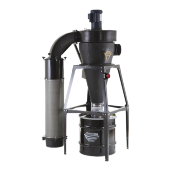
- Page 1 Owner’s Manual V-System Dust Collector 1.5 HP/ 2 HP / 3 HP #XXVM001500 EXP-XXVM020139H #XXVM003000 #XXVM003000W #XXVM003055 #XXVM003055W Patents: www.oneida-air.com/patents Appearance may vary slightly Rev: B 20231025LL Doc. #ZBM000101A...
-
Page 3: Table Of Contents
Table of Contents System Start-Up Information System Specifications Wall Bracket Dimensions Component Dimensions System Dimensions for V-1500 & 35 Gal. Drum System Dimensions for V-3000 & 35 Gal. Drum System Dimensions for V-3000 & 55 Gal. Drum System Contents Assembly Instructions Maintenance Troubleshooting F.A.Q. -
Page 4: System Start-Up Information
13. ENSURE enough air volume is at the suction point to capture all the particulate generated. 14. NEVER make modifications without prior approval from Oneida Air Systems. Modifying the dust collector or using it differently than intended will void the warranty and may result in malfunction or mechanical failure that leads to serious personal injury or death! DO NOT allow use as a toy. - Page 5 system start-up Information (Continued) 15. DO NOT locate or operate the system in moist, wet, poorly lit, or cluttered environments. Operating in these areas can create shock hazards, increase the risks of accidents and injury, and/or lower the operating lifespan of the dust collector. 16.
- Page 6 Oneida Air Systems assumes no responsibility or liability for the suitability of any fire and/ or explosion mitigation strategy, or any items incorporated into a collector as part of an owner/operators hazard mitigation strategy.
- Page 7 system start-up Information (Continued) d. Check wood stock for old nails and screws which can create red-hot metal fragments. 14. DO NOT overload woodworking equipment, especially sanders, as excessive frictional heat can spontaneously ignite dust. Sanders can produce concentrations of dust well into the combustible range. 15.
-
Page 8: System Specifications
Inlet 7" (177.8 mm) Diameter Overall Height (with 35 Gallon Drum) 1.5 HP: 87" (2,209.8 mm) / 3 HP: 88" (2,235.2 mm) Overall Weight 1.5 HP: 189 lbs (85.7 kg) / 3 HP: 202 lbs (91.6 kg) Oneida Air Systems... -
Page 9: Wall Bracket Dimensions
wall Bracket Dimensions 20-1/4" 516 mm 10-1/4" 262 mm 18in systems dimensions 1/4" 8 mm Back Support Brace 3/4" 19 mm 3-1/4" 83 mm 14" 356 mm 14-3/4" 375 mm Left Wall Bracket Right Wall Bracket 16" 406 mm Note: The Wall Bracket is universal to 18" and 21" systems. The blackened holes on the Back Support Brace and Left and Right Wall Brackets in the images above will not be utilized in the V-System installation. -
Page 10: Component Dimensions
6-3/4" 171 mm 17-3/8" 442 mm 13-1/2" 344 mm 14-9/16" 370 mm 26" 661 mm 40" 1,016 mm 35" 889 mm 55 Gallon 22-1/4" 6" 565 mm 152 mm 35 Gallon 23" 23" 584 mm 584 mm Oneida Air Systems... -
Page 11: System Dimensions For V-1500 & 35 Gal. Drum
system Dimensions for V-1500 & 35 Gal. Drum Nominal dimensions shown. Dimensions subject to slight variations in manufacturing. Top View 48" 1,219 mm 16" 406 mm 32-1/2” 826 mm 30" 762 mm 90" 2,286 mm 75" 1,905 mm 14" 356 mm 67"... -
Page 12: System Dimensions For V-3000 & 35 Gal. Drum
30" 762 mm 91" 2,311 mm 75" 1,905 mm 14" 356 mm 58-1/2" 1,486 mm 67" 1,702 mm 39" 991 mm 29" 737 mm 6-1/2" 165 mm 3" 76 mm 27" 686 mm 30" 762 mm 10 Oneida Air Systems... -
Page 13: System Dimensions For V-3000 & 55 Gal. Drum
system Dimensions for V-3000 & 55 Gal. Drum Nominal dimensions shown. Dimensions subject to slight variations in manufacturing. Top View 48-13/16" 1194 mm 16" 32-1/2" 406 mm 762 mm 30" 762 mm 14" 99" 356 mm 2,515 mm 75" 1,905 mm 66-1/2"... -
Page 14: System Contents
You will need the following tools: general Fan hOuSing Filter 8' Ladder Razor Knife Flathead Screwdriver 7/16" Wrench Level Diagonal Cutters Hammer 7/16" Socket Wrench Scissors Tape Measure / Ruler 1/2" Wrench 1/4" Socket 1/2" Socket Wrench Impact Driver 12 Oneida Air Systems... - Page 15 system Contents (Continued) oneida-air.com...
-
Page 16: Assembly Instructions
• Stand Instruction Sheet # ZBI000018 [FIG 1a] • Leg Extension Instruction Sheet # ZBI000013 • Wall Bracket Instruction Sheet and Template # ZBI010018A and ZBT010018 [FIG 1b] FIG. 1a FIG. 1b 14 Oneida Air Systems... - Page 17 assembly Instructions (Continued) Apply Gasket (G4A) making sure that there is no gap where the ends meet: a. Apply to the top rim of the Barrel (C) outside of the bolt holes [FIG. 2a]. Top View b. Apply to the Fan Housing (B) outlet inside the bolt holes [FIG.
- Page 18 Instructions (Continued) Lift the Cone (D) onto the supplied support, making sure to align the Cone’s flange holes with those on the Stand [FIG 4a] or Wall Bracket [FIG 4b]. FIG. 4a FIG. 4b 16 Oneida Air Systems...
- Page 19 assembly Instructions (Continued) Once your cone is aligned with the supplied support, lift the Barrel (C) onto the Cone (D), making sure to align the corresponding flange holes. v [FIG. 5] Note: Loosely tighten only at this time. Once your Fan Housing is installed in the preferred orientation you will need to remove one bolt to install the Support Brace (G3) shown in Step 11.
- Page 20 Housing (B) using eight Flange Bolts (G4D) [FIG. 7b]. Note: Unwrap the braided filter grounding wire from the Motor Assembly's chassis box and let hang loose for future grounding steps [FIG. 7c]. FIG. 7a FIG. 7b FIG. 7c 18 Oneida Air Systems...
- Page 21 assembly Instructions (Continued) Secure Filter Plate (I2), gasket side up, to Filter Plenum Elbow (I1) with nine Bolts (I5C), nine Flat Washers (I5D), and nine Whiz-Lock Nuts (I5E). [FIG. 8a] Support Note: Ensure holes on the Filter Plate line Hanger Ringlet up with those on the Plenum Elbow.
- Page 22 Barrel (C) using the hardware installed in Step 5. [FIG. 11] Tighten all hardware on the flange that was previously loosely tightened. Note: Tighten bolts until snug but not so tightly that the gasket extrudes outside the flange. FIG. 11 20 Oneida Air Systems...
- Page 23 assembly Instructions (Continued) Insert the Drop-in Silencer (I3) into one end of the Filter (H). This end will become the top of the Filter [FIG. 12]. FIG. 12 Install the Stacking Sound Filter (K) [FIG. 13] by referencing the included instruction sheet: • Stacking Sound Filter Sheet #ZBI131800 Note: You will use four J-Bolts (I5A) and four Thumb Nuts (I5B) to install the Stacking Sound...
- Page 24 [FIG. 15]. Note: If you need to extend the wire, you can use any 16 gauge copper stranded wire and connect with wire nuts FIG. 15 22 Oneida Air Systems...
- Page 25 assembly Instructions (Continued) The flex hose connects the cyclone to the dust bin below and only requires enough height to allow the lid to be lifted from the bin. You may shorten the provided 1’ hose length as needed. Attach Hose (G2) to the Cone’s (D) discharge, and secure it in place with the Clamp Band (G1).
- Page 26 WITH FURTHER STEpS. Use the adhesive of your choice to temporarily secure the Magnetic Starter (A1) to the wall [FIG. 18]. To permanently secure the starter to the wall proceed to step 19. FIG. 18 24 Oneida Air Systems...
- Page 27 assembly Instructions (Continued) To permanently secure the Magnetic Starter Mounting (A1) to the wall. Remove the Magnetic Screw Hole Starter cover by loosening the top and bottom screws and exposing the overload and contact connections [FIG 19a]. Set aside the screws. a.
-
Page 28: Maintenance
Per the manufacturer’s specification, lubricate the 1.5HP Baldor motor every 5,500 hours. Refer to the * Special HIGH temperature grease is recommended Table below to determine if your motor’s Lubrication ** Special LOW temperature grease is recommended 26 Oneida Air Systems... -
Page 29: Troubleshooting
Clean filter more often with compressed air. If you continue to experience difficulty with your dust collector, call oneida Air Systems’ Customer Service Department at 1-866-387-8822 or email support@oneida-air.com. oneida-air.com... -
Page 30: F.a.q
What dust can be collected? Oneida Air Systems’ dust collectors are designed and tested for wood and wood dust. They can and have been used effectively for various other dusts and chips, such as drywall dust, paper dust, agricultural dust, metal chips and other forms of debris. - Page 31 F.a.Q. (Continued) Where do I mount the included Dust Sentry? The strobe can be mounted anywhere convenient that is within reach of the wiring. Can I lengthen the Bin level Sensor power cord? The 8' power cord can be extended to any length using wire of the same gauge or higher. Why does the bin level indicator flash when the bin is empty? Because the Dust Sentry works via an adjustable infrared sensor, it can sometimes show false positives with an empty container because of the reflective surface at the bottom of the steel drum.
-
Page 32: Recommended Accessories
RF Remote Control Key Fob #AMR000000 • Sends long range wireless signal via radio frequency. • Works at long distances and even through walls! • Compatible only with systems that include a magnetic motor starter control box. 30 Oneida Air Systems... - Page 33 Universal Drum Dolly #SDD990000 • Fits nearly any cylindrical waste bin sold by Oneida Air Systems. • Includes five 2" non-marking caster wheels (3 non-locking, 2 locking). • Requires Leg Extension Kit (Item #STZ212301) if used with a stand mounted system.
-
Page 34: Warranty Information
In no event shall Oneida Air Systems’ liability under this warranty exceed the purchase price paid for the product and any legal actions brought against Oneida Air Systems shall be tried in the State of New York, County of Onondaga. -
Page 35: Notes
notes oneida-air.com... - Page 36 Regardless of where you purchased your system, if you have any questions or issues with missing / damaged parts, please call Oneida Air Systems first to let us help resolve your problem. We fully stand behind the quality of our products and place the utmost value on customer satisfaction.
Need help?
Do you have a question about the XXVM001500 and is the answer not in the manual?
Questions and answers