
Related Manuals for Oneida Air Systems V1500


Summary of Contents for Oneida Air Systems V1500
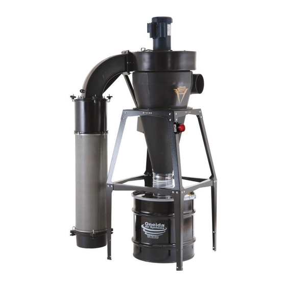
- Page 1 OWNER’S MANUAL V-System Dust Collector 1.5 HP/3 HP #XXVM001500 #XXVM003000 #XXVM003000W #XXVM003055 #XXVM003055W U.S. Patent 8377160, 9370740, 8514090, 8496719, 7247180 Appearance may vary slightly Rev: 11/20/2019 Doc. #ZBM000101A...
-
Page 3: Table Of Contents
Table of Contents System Start-Up Information System Speci cations System Dimensions for V1500 and 35 Gal. Drum System Dimensions for V-3000 and 35 Gal. Drum System Dimensions for V-3000 and 55 Gal. Drum System Contents Assembly Instructions Maintenance Troubleshooting Recommended Accessories Warranty Information oneida-air.com... -
Page 4: System Start-Up Information
5. Check amperage draw on motor with all gates open. Current draw should not exceed maximum motor amperage as stated on motor plate. (Oneida Air Systems is not responsible for damage to motors caused by improper installation, wiring or failure to follow these directions). - Page 5 System Start-Up Information (Continued) d. NFPA664 Code book, “Standard for the Prevention of Fires and Explosions in Wood Processing and Woodworking Facilities”, applies to woodworking operations that occupy areas of more than 5,000 sq. . or to areas where dust producing equipment requires an aggregate dust collection ow rate of more than 1,500 cfm (cubic feet per minute).
-
Page 6: System Speci Cations
Inlet 7" (177.8 mm) Diameter Overall Height (with 35 Gallon Drum) 1.5 HP: 87" (2,209.8 mm) / 3 HP: 88" (2,235.2 mm) Overall Weight 1.5 HP: 189 lbs (85.7 kg) / 3 HP: 202 lbs (91.6 kg) Oneida Air Systems... -
Page 7: Drum
System Dimensions for V1500 and 35 Gal. Drum Nominal dimensions shown. Dimensions subject to slight variations in manufacturing. Top View 47" 1194 mm 13" 30" 32-1/2” 330 mm 762 mm 762 mm 1.5 HP 87" 2210 mm 14" 356 mm 75"... -
Page 8: Drum
32-1/2” 330 mm 762 mm 762 mm 88" 2235 mm 14" 356 mm 75" 63" 56" 1905 mm 1600 mm 1422 mm 36" 914 mm 25" 635 mm 8" 203 mm 27" 686 mm 30" 762 mm Oneida Air Systems... - Page 9 System Dimensions for V-3000 and 55 Gal. Drum Nominal dimensions shown. Dimensions subject to slight variations in manufacturing. Top View 47" 1194 mm 13" 30" 32-1/2" 330 mm 762 mm 762 mm 14" 99" 356 mm 2515 mm 75" 1905 mm 87"...
-
Page 10: System Contents
You will need the following tools: GENERAL FAN HOUSING FILTER 8" Ladder Razor Knife Flathead Screwdriver 7/16" Wrench Level Diagonal Cutters Hammer 7/16" Socket Wrench Scissors Tape Measure / Ruler 1/2" Wrench 1/4" Socket 1/2" Socket Wrench Impact Driver Oneida Air Systems... - Page 11 System Contents (Continued) oneida-air.com...
-
Page 12: Assembly Instructions
[FIG 1a] or wall-bracket [FIG 1b] refer to the included instruction sheets: • Stand Instruction Sheet # ZBI000018 • Leg Extension Instruction Sheet # ZBI000013 • Wall Bracket Instruction Sheet and Template # ZBI010018A and ZBT010018 10 Oneida Air Systems... - Page 13 Assembly Instructions (Continued) Orient the Fan Housing (B) so that the molded “UP” text is visible and facing towards you. Push the U-Spring Nuts (G4C) onto each of the holes lining the inside circle of the Fan Top View Housing, making sure that the U-Spring Nuts align into the bolt holes of the housing.
- Page 14 NO air leaks. FIG. 4 Li the Cone (D) onto the stand, making sure to align the Cone’s ange holes with those on the stand [FIG 4]. FIG. 5 12 Oneida Air Systems...
- Page 15 Assembly Instructions (Continued) Once your cone is aligned with the stand, li the Barrel (C) onto the Cone (D), making sure to align the corresponding ange holes. [FIG. Secure both components to the stand using eight Flange Bolts (G4D) and eight 5/16" Flat Washers (G4G), and eight Nylock Nuts (G4F).
- Page 16 Note: Ensure holes on the Filter Plate line up with those on the Plenum Elbow. hole pattern is asymmetrical. [FIG. 9b] rectangular sha on the Bolt (I5B) must push through the holes on the Filter Plate (I2). FIG. 9a FIG. 9b 14 Oneida Air Systems...
- Page 17 Assembly Instructions (Continued) Secure the Filter Plenum Elbow (I1) to the outlet on the Fan Housing (B) using six Flange Bolts (G4D) and six Whiz-Lock Nuts (G4E). Support Outlet Hanger Leave lower outer corner empty for Step 10. Ringlet [FIG. 10] Note: e Plenum Elbow should be oriented so that the support hanger ringlet is closest to the...
- Page 18 Note: Tighten bolts until snug but not so tightly that the gasket extrudes outside the ange. Insert the Drop-In Silencer (I3) into the top of the Filter (H) [FIG. 12]. FIG. 12 16 Oneida Air Systems...
- Page 19 Assembly Instructions (Continued) To install the Stacking Sound Filter (K) [FIG. 13] refer to the included instruction sheet: • Stacking Sound Filter Sheet #ZBI131816 FIG. 13 Attach the Fine Dust Bin (I4) to the Filter (H) with four J-Bolts (I5A) and four umb Nuts (Ih5B) as in [FIG.
- Page 20 Flex Hose (G2) using a razor knife and diagonal cutter to cut through the clear lining and reinforcing wire. Note: Be careful to only remove 0.5” at a time so as not to over trim. FIG. 15 18 Oneida Air Systems...
- Page 21 Assembly Instructions (Continued) To ground the lter, attach the ring terminal on the braided ground wire from the Motor Assembly (A) to a bolt on the lter plate, under the nut, then attach the alligator clip to the lter’s cage [FIG. 16]. Note: If you need to extend the wire, you can use any 16 gauge copper stranded wire and connect with wire nuts...
-
Page 22: Maintenance
Per the manufacturer’s speci cation, lubricate the 1.5HP Baldor motor every 5,500 hours. Refer to the * Special HIGH temperature grease is recommended Table below to determine if your motor’s Lubrication ** Special LOW temperature grease is recommended 20 Oneida Air Systems... -
Page 23: Troubleshooting
2. Heavy sanding with a drum sander or ne grit paper will cause the pleated lter media to blind sooner than with larger size dust. Clean lter more often with compressed air. If you continue to experience difficulty with your dust collector, call Oneida Air Systems’ Customer Service Department at 1-866-387-8822 or email support@oneida-air.com. oneida-air.com... -
Page 24: Recommended Accessories
RF Remote Control Key Fob #AMR000000 • Sends long range wireless signal via radio frequency. • Works at long distances and even through walls! • Compatible only with systems that include a magnetic motor starter control box. 22 Oneida Air Systems... - Page 25 Universal Drum Dolly #SDD990000 • Fits nearly any cylindrical waste bin sold by Oneida Air Systems. • Includes ve 2" non-marking caster wheels (3 non-locking, 2 locking). • Requires Leg Extension Kit (Item #STZ212301) if used with a stand mounted system.
-
Page 26: Warranty Information
Oneida Air Systems makes every e ort to accurately represent our products and prices, however Oneida Air Systems reserves the right to make changes to products and prices at any time. As a manufacturer, Oneida Air Systems reserves the right to change product speci cations at any time in an e ort to achieve better quality products. - Page 27 Notes oneida-air.com...
- Page 28 Regardless of where you purchased your system, if you have any questions or issues with missing / damaged parts, please call Oneida Air Systems rst to let us help resolve your problem. We fully stand behind the quality of our product and place the utmost value on our customer’s satisfaction.
Need help?
Do you have a question about the V1500 and is the answer not in the manual?
Questions and answers