Table of Contents

Related Manuals for Oneida Air Systems V-System XXVS300035


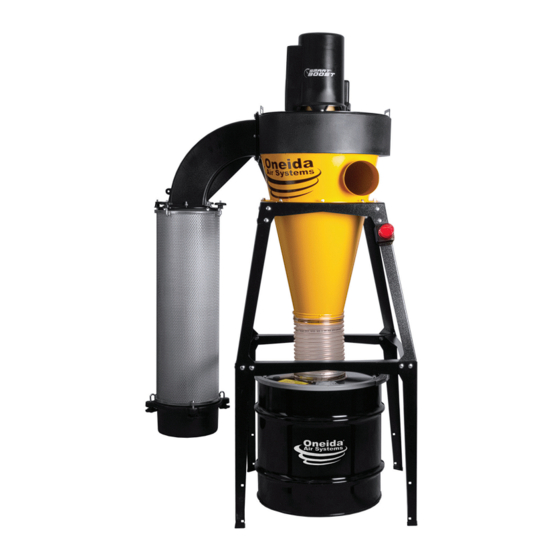
Summary of Contents for Oneida Air Systems V-System XXVS300035
- Page 1 OWNER’S MANUAL V-System ® with SMART Boost ® # XXVS300035 # XXVS300055 # XXVS300035W # XXVS300055W US Pat. 8496719, 8377160, 8514090, 9370740, D908854, 7247180, 8491685 Appearance may vary slightly Rev: B 20221019LL Doc. #ZBM000046...
-
Page 3: Table Of Contents
Table of Contents System Start-Up Information System Specifications Stand and Leg Extension Dimensions System Dimensions for 35 Gallon Drum System Dimensions for 55 Gallon Drum System Contents Assembly Instructions Maintenance Troubleshooting F.A.Q. Recommended Accessories Warranty Information Notes oneida-air.com... -
Page 4: System Start-Up Information
Facilities”, applies to woodworking operations that occupy areas of more than 5,000 sq. ft. or to areas where dust producing equipment requires an aggregate dust collection flow rate of more than 1,500 cfm (cubic feet per minute). Oneida Air Systems, Inc. - Page 5 System Start-Up Information (Continued) This exempts some small operators from the NFPA code 664, but other codes may apply in your jurisdiction. Consult your local Fire Marshal for help. Additional information can be found in NFPA Code Book 664. 4. The customer assumes the responsibility for contacting their insurance underwriter regarding specific application requirements of explosion venting or if additional fire protection and safety equipment may be required.
-
Page 6: System Specifications
E12 Minimum Efficiency Rating Filter Surface Area 95 sq. ft. SYSTEM DIMENSIONS AND CONSTRUC TION Barrel/Cyclone Body Heavy-gauge cold-rolled steel Inlet 6" Diameter Overall Height (with 35 Gallon Drum) 84" Overall Height (with 55 Gallon Drum) 96" Oneida Air Systems... -
Page 7: Stand And Leg Extension Dimensions
Stand and Leg Extension Dimensions The Angle Bracket Leg Extension Kit (#STZ212301) is included with the 55 gallon drum kits. The Ÿ Leg Extensions are required for the 35 gallon drum kits if you purchased the Universal Drum Dolly (#SDD990000) or the 13" Stacking Sound Filter (#BSS131400). Nominal dimensions shown. -
Page 8: System Dimensions For 35 Gallon Drum
406 mm 30" 764 mm 33" 838 mm 83-7/8" 2,130 mm 65-1/2" 1,666 mm 54-1/4" 1,379 mm 58-1/4" 1,481 mm 36" 914 mm 25-1/2" 646 mm 6-1/8" 157 mm 7-1/2" 191 mm 27" 686 mm 30" 762 mm Oneida Air Systems... -
Page 9: System Dimensions For 55 Gallon Drum
System Dimensions for 55 Gallon Drum Nominal dimensions shown with a 55 gallon drum. Dimensions subject to slight variations in manufacturing. Top View 49" 49" 1,243 mm 1,243 mm 16" 16" 406 mm 406 mm 30" 30" 764 mm 764 mm 33"... -
Page 10: System Contents
You will need the following tools: GENER AL FAN HOUSING FILTER 8' Ladder Razor Knife Flathead Screwdriver 7/16" Wrench Level Diagonal Cutters Hammer 7/16" Socket Wrench Scissors Tape Measure / Ruler 1/2" Wrench 1/4" Socket 1/2" Socket Wrench Impact Driver Oneida Air Systems... - Page 11 System Contents (Continued) Note: Attached to the Motor Assembly (A) oneida-air.com...
-
Page 12: Assembly Instructions
Wall Bracket Template # ZBT300021 [FIG 2] Note: The Leg Extensions (O) are required if you purchased the 35 Gallon Kit (XGK030035) and Oneida Air Systems' Stacking Sound Filter. FIG. 1 FIG. 2 FIG. 3 10 Oneida Air Systems... - Page 13 Assembly Instructions (Continued) Apply Gasket (J1) making sure that there is no gap where the ends meet: a. Apply to the top flange of the Cone (C) outside the bolt holes [FIG. 2a]. b. Apply to the Filter Plate (I2); it may partially cover the bolt holes.
- Page 14 Note: If you know the orientation of your fan housing’s outlet, test the location of the plenum support brace, and leave the corresponding hole free. See steps 9 and 10 for further clarification. FIG. 3a FIG. 3b 12 Oneida Air Systems...
- Page 15 Assembly Instructions (Continued) Lift the Fan Housing (B) onto the Cone FIG. 4a (C), making sure it is oriented so that the molded “UP” text is visible [FIG 4a]. Align the housing’s holes with the holes in the Cone and keep in mind the direction you want your outlet to face.
- Page 16 Secure the Motor Assembly to the Fan Housing using seven Flange Bolts (J3). [FIG. 6b]. Note: The eighth hole (indicated by X) on the Fan Housing (B) does not require a bolt because it is inaccessible [FIG. 6a]. FIG. 6a FIG. 6b 14 Oneida Air Systems...
- Page 17 Assembly Instructions (Continued) Secure Filter Plate (I2), gasket side up, to Filter Plenum Elbow (I1) with nine Bolts (I5C), nine Flat Washers (I5D), and nine Whiz-Lock Nuts (I5E). [FIG. 7a] Support Note: Ensure holes on the Filter Plate line Hanger Ringlet up with those on the Plenum Elbow.
- Page 18 Install other end of the Support Brace (K) to the flange of the Cone (C) using the hardware installed in Step 3 [FIG. 10]. Note: The hardware removed will depend on your outlet’s orientation. FIG. 10 16 Oneida Air Systems...
- Page 19 Assembly Instructions (Continued) Insert the Drop-In Silencer (I3) into one end of the Filter (H). This end will become the top of the Filter [FIG. 11]. FIG. 11 Attach the Fine Dust Bin (I4) to the bottom of the Filter (I) with four J-Bolts (I5A) and four Thumb Nuts (I5B) as shown in [FIG.
- Page 20 Drum, you may trim the Hose using a razor knife and diagonal cutter to cut through the clear lining and reinforcing wire. Note: Be careful to only remove 0.5" at a time so as not to over trim. FIG. 14 18 Oneida Air Systems...
- Page 21 Assembly Instructions (Continued) Statically ground the Drum (G) by attaching the 14" Grounding Cable (J7); Drive the 3/8" Self-Tapping Screw through its eyelet and into the bottom of the Cone (C) just above the installed Flex Hose (E). Repeat using the second 3/8"...
- Page 22 FIG. 17b Reattach the cover with the screws set aside in Step 17 [FIG 18]. START STOP FIG. 18 To install the Dust Sentry (N) [FIG. 19], refer to the included instruction sheet: • Dust Sentry Sheet #ZBI000002A FIG. 19 20 Oneida Air Systems...
-
Page 23: Maintenance
Maintenance Lubricating the Motor UNPLUG YOUR UNIT BEFORE SERVICING OR CLEANING Per the motor's specifications, their 2-pole motors (3,600 RPM) are to be lubricated every 5,500 hours. Cleaning the Filter Refer to the Table below to determine if your motor’s lubrication interval must be adjusted. -
Page 24: Troubleshooting
2. If there is no room to remove the cowling, unplug your system for 1 minute. If you continue to experience difficulty with your dust collector, call Oneida Air Systems’ Customer Service Department at 1-866-387-8822 or email support@oneida-air.com. 22 Oneida Air Systems... -
Page 25: F.a.q
What dust can be collected? Oneida Air Systems’ dust collectors are designed and tested for wood and wood dust. They can and have been used effectively for various other dusts and chips, such as drywall dust, paper dust, agricultural dust, metal chips and other forms of debris. - Page 26 Is this remote IR or RF? All of our current remote control products operate via Radio Frequency (RF). What type of battery does the Remote (M) use? The remote control keyfob uses an A23 type battery. Oneida Air Systems, Inc.
-
Page 27: Recommended Accessories
Recommended Accessories 13" x 39" Spunbond Filter #FCS133995 • Specially designed for high airflow performance with minimal pressure drop. • Durable polyester pleating material with external, reinforcing steel wire frame. • Independently lab tested and verified filtration media. 13" x 36 HEPA Media Filter #FCS133695HF • Independently tested G.E. - Page 28 Universal Drum Dolly #SDD990000 • Fits nearly any cylindrical waste bin sold by Oneida Air Systems. • Includes five 2" non-marking caster wheels (3 non-locking, 2 locking). • Requires Leg Extension Kit (Item #STZ212301) if used with a stand mounted system.
-
Page 29: Warranty Information
In no event shall Oneida Air Systems’ liability under this warranty exceed the purchase price paid for the product and any legal actions brought against Oneida Air Systems shall be tried in the State of New York, County of Onondaga. -
Page 30: Notes
Notes 28 Oneida Air Systems... - Page 31 oneida-air.com...
- Page 32 Regardless of where you purchased your system, if you have any questions or issues with missing / damaged parts, please call Oneida Air Systems first to let us help resolve your problem. We fully stand behind the quality of our products and place the utmost value on customer satisfaction.
Need help?
Do you have a question about the V-System XXVS300035 and is the answer not in the manual?
Questions and answers