
Subscribe to Our Youtube Channel
Related Manuals for Oneida Air Systems XXK100300


Summary of Contents for Oneida Air Systems XXK100300
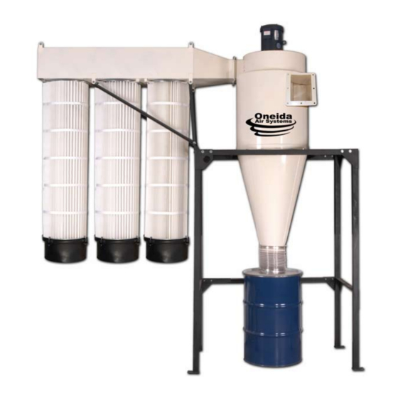
- Page 1 ZBM000017 10 HP Direct Drive Dust Collectors 9_11 Owner’s Manual Oneida Air Systems, Inc. 1001 West Fayette St., Syracuse, NY 13204 Phone 1.800.732.4065 315.476.5151 Fax 315.476.5044 www.oneida-air.com...
-
Page 2: Table Of Contents
Thank You for Choosing an Oneida Air Systems Product! OAS manufactures and sells dust collection equipment only. Our qualified technicians and sales staff are available 7:30am - 6:00pm EST Mon. - Thurs. and 7:30am - 5:00pm EST Fri. to answer any ques- tions concerning OAS products and dust collection. -
Page 3: System Start-Up Information
I. System Start-Up Information 1. Read the installation and maintenance instructions as well as the recommended safety practices in this manual. 2. Install Ductwork completely: (A.) Seal ductwork with silicone sealant or duct tape. (B.) Have Dust Bin in place and sealed. 3. -
Page 4: General Assembly
II. General Assembly - XXK100300 - 3 Phase 10hp Direct Drive System - XXK010300 3 phase 9. 55 gal. Steel Drum Kit - SEK551001 1. Motor Blower Assembly - BXI050100 - 1ph - BXI070300 - 3ph 9a. Drum Lid w/ 10” ring - SEX55100 1a. -
Page 5: General Specifications & Fan Performance Curve
III. General Specifications & Fan Performance Curves Physical and Electrical Data for 10hp Direct Drive Systems Dust Bin System Performance 55 Gal. Steel Drum 10hp - 3800 cfm @ 2.3” SP no filter Large Dust Bins available System Dimensions Sound Fan Wheel Diameter: 17”... -
Page 6: Dimensions
IV. Dimensions For minimum mounting heights with 55 gal. drum 115.9 10hp Direct Drive © O.A.S. 2010... - Page 7 V. Angle Iron Stand 10hp Direct Drive © O.A.S. 2010...
- Page 8 VI. Assembly Instructions 10hp Direct Drive © O.A.S. 2010...
- Page 9 VI. Assembly Instructions (Cont.) Wait a few minutes 5. Attach flex hose to bot- Filter for internal dust to tom of collector and to lid settle then unscrew of dust bin. Securely fas- thumb nuts from J-Hook J-Hooks and remove ten hose clamps.
-
Page 10: Fan / Blower Maintenance
VII. Fan / Blower Maintenance A high pressure blower requires a certain amount of resistance which will prevent motor over amperage. Make sure power source matches wire voltage configurations. Check set screw and key in fan wheel, make sure fan wheel is secure. Fan blower should not vibrate. 1. -
Page 11: Filter Maintenance
VIV. External Filter Maintenance All steps should be done with a dust mask and eye protection. Proper filter clean- ing should not be neglected. A dirty filter can affect dust collector operation and filter life. 1. Compressed air from outside. Blast air along pleats of the filter at about a 20 degree angle. - Page 12 VIII. Single and Three Phase Wire Diagram Use wiring diagram on motor plate if different from below. Wiring should always be done by a licensed electrician! - Electrically insulate all connections. - For counter-clockwise rotation, looking from top of motor down. Motor Wire Green...
-
Page 13: Accessories
XI. Accessories Air Locks - Rotary air locks provide an alternative to an air tight dust bin for larger volume capacity and less maintenance. Bin Level Monitor - AIB000000 - Provides level sensing for dry bulk solids. The monitor operates by using a 1 rpm synchronous motor to rotate a paddle. When paddle rotation is impeded by material surrounding it, the motor is de-energized and triggers a SPDT snap switch. -
Page 14: Troubleshooting
Note: If you continue to experience difficulty with your collector, call Motor Overheating Oneida Air Systems at The motor’s internal circuit breaker will trip if the motor is overheating. 1.800.732.4065 for assis- Motor amperage too high - Shut system down. - Page 15 XIII. Fire Hazards - Read Before Installing and Operating Oneida Collectors are designed for WOOD DUST only!! Wood shaping and cutting processes generate wood chips, shavings, and dust. These materials are considered combustible. Air borne wood dust below 420 microns in size (,017 of an inch) in certain concentration ranges when ignited can deflagrate (burn quickly). An ignition source such as a spark or ember can ignite a dust mixture resulting in an expanding flame front which can cause an explo- sion if tightly contained.
-
Page 16: Terms And Conditions
Returned Goods Policy Buyer must inform Oneida Air Systems of any shortage or damage, by so noting in writing, on the freight delivery bill prior to signing to indicate receipt of shipment. All claims covered under the limited warranty, are subject to inspection and investigation by Oneida Air Systems. Oneida Air Systems reserves the right to inspect and investigate all returned products before Buyer’s claim is settled. - Page 17 XV. Filter Efficiency Gauge Mounting Instructions Air Flow to Filter Silicone Washer Mounting Instructions 1. Mount brass static pressure tube in plenum with tip pointed into the air stream. Use provided washers and nut. Refer to drawings for location of brass static pressure tube.
-
Page 18: Fan Motor Lunbrication
XVI. Fan Motor Lubrication Per Baldor specifications, their 2 pole motors (3600 RPM) motors are to be relubricated every 5500 hours. 10hp Direct Drive © O.A.S. 2010... -
Page 19: Supplemental Instructions For Magnetic Motor Starters
Oneida Air Systems Dust Collectors Please see complete manufacturer instructions for more information. This supplement is designed to aid Oneida Air Systems customers with frequently asked questions. You must have this product installed by a qualified and licensed electrician. Improper installation is very dangerous and will void your warranty. - Page 20 Open access cover on the overload, then set the overload amperage dial to match the FLA amperage of your motor. The FLA value can be found on your motor nameplate. Be sure you have the proper voltage available for your Starter’s Power & Control Circuit (Control circuit controls Contactor Coil in Starter).
- Page 21 Circuit Breaker or disconnect here as required by code. Note: Select size of fuse or circuit breaker per article 430.32 of the NEC (NFPA 70) 3O only Move this Wire to L2 for Single O White Yellow Plug-In Connector OL / Reset Brown Install this Jumper for Single O Using the Same...
Need help?
Do you have a question about the XXK100300 and is the answer not in the manual?
Questions and answers