Table of Contents
Advertisement
Quick Links
OWNER'S MANUAL
U.S. Patent: #8491685,
#9370740, #8514090,
#8496719, #7247180,
D908854, and patent pending
Rev: 03/05/2021
Appearance may vary slightly
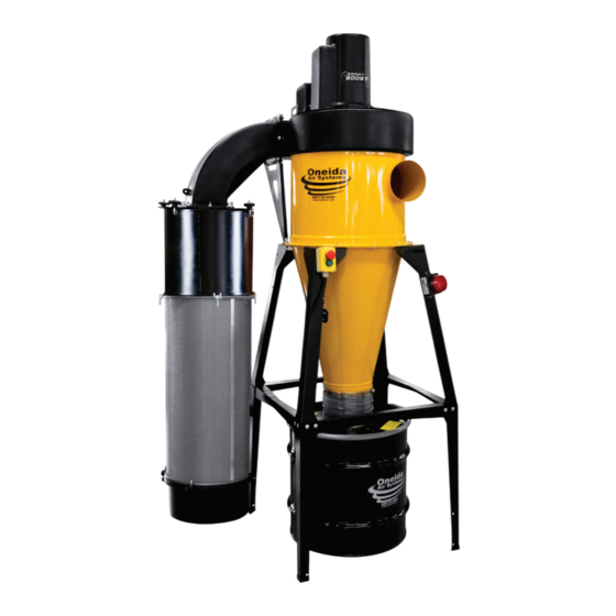
Dust Gorilla Pro
Dust Collector
with SMART Boost
# XGK030035
# XGK030055
# XGK030035W
# XGK030055W
# XGK050035
# XGK050055
# XGK050035W
# XGK050055W
Doc. #ZBM000104
3 HP/5 HP
Advertisement
Table of Contents

Related Manuals for Oneida Air Systems XGK030035


Summary of Contents for Oneida Air Systems XGK030035
- Page 1 OWNER’S MANUAL Dust Gorilla Pro Dust Collector with SMART Boost 3 HP/5 HP # XGK030035 # XGK030055 # XGK030035W U.S. Patent: #8491685, # XGK030055W #9370740, #8514090, # XGK050035 #8496719, #7247180, # XGK050055 D908854, and patent pending # XGK050035W # XGK050055W...
-
Page 3: Table Of Contents
Table of Contents System Start-Up Information System Specifications for 3 HP System Specifications for 5 HP System Dimensions for 35 Gallon Drum System Dimensions for 55 Gallon Drum System Contents Assembly Instructions Maintenance Troubleshooting F.A.Q. Recommended Accessories Warranty Information Notes oneida-air.com... -
Page 4: System Start-Up Information
Facilities”, applies to woodworking operations that occupy areas of more than 5,000 sq. ft. or to areas where dust producing equipment requires an aggregate dust collection flow rate of more than 1,500 cfm (cubic feet per minute). Oneida Air Systems, Inc. - Page 5 System Start-Up Information (Continued) This exempts some small operators from the NFPA code 664, but other codes may apply in your jurisdiction. Consult your local Fire Marshal for help. Additional information can be found in NFPA Code Book 664. 4. The customer assumes the responsibility for contacting their insurance underwriter regarding specific application requirements of explosion venting or if additional fire protection and safety equipment may be required.
-
Page 6: System Specifications For 3 Hp
99.97% @ 0.3 microns Filter Surface Area 110 Sq. Ft. SYSTEM DIMENSIONS AND CONSTRUC TION Barrel/Cyclone Body Heavy-gauge cold-rolled steel Inlet 7" Diameter Overall Height (with 35 Gallon Drum) 94" Overall Height (with 55 Gallon Drum) 106" Oneida Air Systems... -
Page 7: System Specifications For 5 Hp
System Specifications for 5 HP OPER ATION Fan Rating (Free Fan) 5 HP: 3,250 CFM Fan Rating (with Cyclone & Filter) 5 HP: 1,625 CFM at 3" WC Maximum Suction Rating 5 HP: 23" WC MOTOR AND ELEC TRIC AL Motor Type U.S. -
Page 8: System Dimensions For 35 Gallon Drum
219 mm 18" 457 mm 30" 762 mm 94" 2,388 mm 75-1/2" 1,918 mm 16" 406 mm 56" 66-1/2" 1,422 mm 1,689 mm 36" 914 mm 25" 635 mm 8" 203 mm 27" 686 mm 30" 762 mm Oneida Air Systems... -
Page 9: System Dimensions For 55 Gallon Drum
System Dimensions for 55 Gallon Drum Nominal dimensions shown with a 55 gallon drum. Dimensions subject to slight variations in manufacturing. Top View 48" 219 mm 18" 457 mm 30" 762 mm 106" 2,692 mm 87-1/2" 2,223 mm 16" 406 mm 78-1/2"... -
Page 10: System Contents
You will need the following tools: GENER AL FAN HOUSING FILTER 8" Ladder Razor Knife Flathead Screwdriver 7/16" Wrench Level Diagonal Cutters Hammer 7/16" Socket Wrench Scissors Tape Measure / Ruler 1/2" Wrench 1/4" Socket 1/2" Socket Wrench Impact Driver Oneida Air Systems... - Page 11 System Contents (Continued) Note: Sent out attached to the Motor Assembly (A) oneida-air.com...
-
Page 12: Assembly Instructions
• Stand Instruction Sheet # ZBI000014 [FIG 1a] • Leg Extension Instruction Sheet # ZBI000013 • Wall Bracket Instruction Sheet and Template # ZBI300021A and ZBT300021 [FIG 1b] FIG. 1a FIG. 1b 10 Oneida Air Systems... - Page 13 Assembly Instructions (Continued) Apply Gasket (K1) making sure that there is no gap where the ends meet: a. Apply to the top flange of the Cone (D) inside the bolt holes [FIG. 2a]. Top View Top View b. Apply to the top rim of the Barrel (C) outside of the bolt holes [FIG.
- Page 14 Assembly Instructions (Continued) Lift the Cone (D) onto the supplied support, making sure to align the Cone’s flange holes with those on the Stand [FIG 3a] or Wall Bracket [FIG 3b]. FIG. 3a FIG. 3b 12 Oneida Air Systems...
- Page 15 Assembly Instructions (Continued) Once your cone is aligned with the supplied support, lift the Barrel (C) onto the Cone (D), making sure to align the corresponding flange holes. Secure both components to the support using twelve Flange Bolts (K2A) and twelve Whiz-Lock Nuts (K2B) [FIG 4].
- Page 16 Unwrap the braided filter grounding wire FIG. 6a from the Motor cowling and let hang loose for future grounding steps [FIG. 7c]. Also, unclip the Remote from the Filter Grounding Wire [FIG. 6d]. FIG. 6b FIG. 6c FIG. 6d 14 Oneida Air Systems...
- Page 17 Assembly Instructions (Continued) Secure Filter Plate (J2), gasket side up, to Filter Plenum Elbow (J1) with nine Bolts (J5C), nine Flat Washers (J5D), and nine Whiz-Lock Nuts (J5E). [FIG. 7a] Support Note: Ensure holes on the Filter Plate line Hanger up with those on the Plenum Elbow.
- Page 18 Install other end of the Support Brace (L) to the flange of the Barrel (C) using the hardware installed in Step 4 [FIG. 10]. Note: The hardware removed will depend on your outlet’s orientation. FIG. 10 16 Oneida Air Systems...
- Page 19 Assembly Instructions (Continued) Insert the Drop-In Silencer (J3) into one end of the Filter (I). This end will become the top of the Filter [FIG. 11]. FIG. 11 Install the Stacking Sound Filter (N) [FIG. 12] by referencing the included instruction sheet: • Stacking Sound Filter Sheet #ZBI131816 Note: You will use the four J-Bolts (J5A) and four Thumb Nuts (J5B) to install the Stacking...
- Page 20 Thumb Nut, then attach the alligator clip to the filter’s cage [FIG. 14]. Note: If you need to extend the wire, you can use any 16 gauge copper stranded wire and connect with wire nuts FIG. 14 18 Oneida Air Systems...
- Page 21 Assembly Instructions (Continued) The flex hose connects the cyclone to the dust bin below and only requires enough height to allow the lid to be lifted from the bin. You may shorten the provided 1’ hose length as needed. Attach Hose (F) to the Cone’s (D) discharge, and secure it in place with the Clamp Band (E).
- Page 22 PROCEEDING WITH FURTHER STEPS. Use the adhesive of your choice to temporarily secure the starter to the wall [FIG. 17]. To permanently secure the starter to the wall proceed to step 18, otherwise proceed to step FIG. 17 20 Oneida Air Systems...
- Page 23 Assembly Instructions (Continued) To permanently secure the starter to the wall, Mounting Screws Holes take off the starter cover by removing the top and bottom screws and exposing the overload and contact connections [FIG 18a]. Set aside the screws. START a.
-
Page 24: Maintenance
Corrosion Severe Dirt; > 122° F (50° C) Extreme Abrasive Dust; or Class H Insulation* Corrosion < -22° F (-30° C)** Temperature * Special HIGH temperature grease is recommended ** Special LOW temperature grease is recommended 22 Oneida Air Systems... -
Page 25: Troubleshooting
2. If there is no room to remove the cowling, unplug your system for 1 minute. If you continue to experience difficulty with your dust collector, call Oneida Air Systems’ Customer Service Department at 1-866-387-8822 or email support@oneida-air.com. oneida-air.com... -
Page 26: F.a.q
What dust can be collected? Oneida Air Systems’ dust collectors are designed and tested for wood and wood dust. They can and have been used effectively for various other dusts and chips, such as drywall dust, paper dust, agricultural dust, metal chips and other forms of debris. - Page 27 F.A.Q. (Continued) Where do I mount the included Dust Sentry? The strobe can be mounted anywhere convenient that is within reach of the wiring. Can I lengthen the Bin Level Sensor power cord? The 8' power cord can be extended to any length using wire of the same gauge or higher. Why does the bin level indicator flash when the bin is empty? Because the Dust Sentry works via an adjustable infrared sensor, it can sometimes show false positives with an empty container because of the reflective surface at the bottom of the steel drum.
-
Page 28: Recommended Accessories
RF Remote Control Key Fob #AMR000000 • Sends long range wireless signal via radio frequency. • Works at long distances and even through walls! • Compatible only with systems that include a magnetic motor starter control box. 26 Oneida Air Systems... - Page 29 Universal Drum Dolly #SDD990000 • Fits nearly any cylindrical waste bin sold by Oneida Air Systems. • Includes five 2" non-marking caster wheels (3 non-locking, 2 locking). • Requires Leg Extension Kit (Item #STZ212301) if used with a stand mounted system.
-
Page 30: Warranty Information
In no event shall Oneida Air Systems’ liability under this warranty exceed the purchase price paid for the product and any legal actions brought against Oneida Air Systems shall be tried in the State of New York, County of Onondaga. -
Page 31: Notes
Notes oneida-air.com... - Page 32 Regardless of where you purchased your system, if you have any questions or issues with missing / damaged parts, please call Oneida Air Systems first to let us help resolve your problem. We fully stand behind the quality of our products and place the utmost value on customer satisfaction.
Need help?
Do you have a question about the XGK030035 and is the answer not in the manual?
Questions and answers