Table of Contents
Advertisement
Quick Links
Advertisement
Table of Contents

Related Manuals for Dahua N41C1P


Summary of Contents for Dahua N41C1P
- Page 1 Network Video Recorder User's Manual Dahua North America V2.3.1...
-
Page 2: Foreword
User's Manual Foreword General This user’s manual (hereinafter referred to be "the Manual") introduces the installation, functions and operations of the Network Video Recorder (NVR) devices (hereinafter referred to be "the Device"). Read carefully before using the Device, and keep the manual safe for future reference. - Page 3 User's Manual Version Revision Content Release Time ● Added some models. ● Updated the web login page. V1.3.0 November 2021 ● Added privacy masking. Added Analytics+ codec. ● Combined Analytics+ and non-Analytics+ V1.1.0 May 2021 models and deleted discontinued models. V1.0.10 Added several models.
- Page 4 User's Manual About the Manual ● The manual is for reference only. If there is inconsistency between the manual and the actual product, ● We are not liable for any loss caused by the operations that do not comply with the manual.
-
Page 5: Important Safeguards And Warnings
User's Manual Important Safeguards and Warnings This section introduces content covering the proper handling of the Device, hazard prevention, and prevention of property damage. Read carefully before using the Device, and comply with the guidelines when using it. Transportation Requirements Transport the Device under allowed humidity and temperature conditions. - Page 6 User's Manual ● Do not place the Device in a place exposed to sunlight or near heat sources. ● Keep the Device away from dampness, dust, and soot. ● Put the Device in a well-ventilated place, and do not block its ventilation. ●...
-
Page 7: Table Of Contents
1.1 Overview ................................ 1 1.2 Features ................................. 1 2 Front Panel and Rear Panel ..........................4 2.1 Front Panel ..............................4 2.1.1 N41C1P/N41C2P ..........................4 2.1.2 N42C1P/N42C2P/N42C3P/N52B5P/N54A4P/N54B3P/N54B5N ..........6 2.1.3 N82B2P/N82B3P/N82B5P ........................ 7 2.1.4 N84B3P/N84B3N/N84B5N ......................8 2.1.5 N98A5N/N98A6N/N98A7N ......................9 2.2 Rear Panel ..............................10... - Page 8 User's Manual 4 Starting the Device ............................30 5 Local Operations ..............................31 5.1 Initialization ..............................31 5.2 Startup Wizard ............................34 5.3 Login ................................39 5.4 Main Menu ..............................41 5.5 Quick Operation Bar ..........................43 5.6 Live View ..............................44 5.6.1 Live Page............................
- Page 9 User's Manual 5.6.7.4.6 Auxiliary Button ......................68 5.6.8 Wireless Pairing ..........................68 5.6.9 Sequence ............................69 5.6.10 Fisheye ............................. 72 5.6.10.1 Fisheye De-warp on Live View Interface ................72 5.6.10.2 Fisheye De-warp During Playback ..................74 5.6.11 Temperature Monitoring ......................74 5.6.12 Shortcut Menu to Add Camera ....................
- Page 10 User's Manual 5.8.2 Search and Playback ........................109 5.8.2.1 Search Page ..........................109 5.8.2.2 Playback ...........................111 5.8.2.3 Smart Search Playback ......................114 5.8.2.4 Clipping Videos ........................114 5.8.2.5 Backing Up ..........................115 5.8.2.6 File List ............................. 116 5.8.2.7 Tag Playback........................... 116 5.8.3 Recording Information ........................
- Page 11 User's Manual 5.9.6 IVS ..............................139 5.9.6.1 Enabling Smart Plan ......................139 5.9.6.2 Configuring IVS ........................140 5.9.6.2.1 Tripwire .......................... 140 5.9.6.2.2 Intrusion ........................142 5.9.6.2.3 Abandoned Object Detection ..................145 5.9.6.2.4 Fast Moving ........................148 5.9.6.2.5 Parking ..........................151 5.9.6.2.6 Crowd Gathering......................
- Page 12 User's Manual 5.9.10.3 Report Query ........................184 5.9.11 People Counting ........................... 185 5.9.11.1 Enabling Smart Plan ......................185 5.9.11.2 Configuring People Counting ................... 185 5.9.11.3 Configuring In Area No...................... 187 5.9.11.4 Queuing..........................188 5.9.11.5 Report Query ........................189 5.9.12 Heat Map ............................189 5.9.12.1 Enabling Smart Plan ......................
- Page 13 User's Manual 5.10.5.5 PIR Alarm ..........................212 5.10.6 Audio Detection ........................... 214 5.10.7 Thermal Alarm ..........................214 5.10.8 Exception ............................215 5.10.9 Disarming ............................217 5.11 Network ..............................218 5.11.1 TCP/IP.............................. 218 5.11.2 Routing Table ..........................222 5.11.3 Port ..............................222 5.11.4 External Wi-Fi ..........................
- Page 14 User's Manual 5.12.6.1 Manual Check ........................253 5.12.6.2 Detection Report ......................... 254 5.12.6.3 Disk Health Monitoring ..................... 256 5.12.7 Record Estimate ........................... 257 5.12.7.1 Calculating Recording Time ....................259 5.12.7.2 Calculating HDD Capacity for Storage ................259 5.12.8 FTP ..............................260 5.12.9 iSCSI ...............................
- Page 15 User's Manual 5.15.1 General Settings ........................... 291 5.15.1.1 General ........................... 291 5.15.1.2 Date and Time ........................293 5.15.1.3 Holiday ..........................295 5.15.2 Serial Port ............................297 5.16 Output and Display ..........................298 5.16.1 Display ............................298 5.16.2 Tour ..............................300 5.16.3 Custom Layout ..........................
- Page 16 User's Manual 5.19.4.4 System Update ........................325 5.19.4.4.1 Upgrading File ......................325 5.19.4.4.2 Online Upgrade ......................326 5.19.4.4.3 Uboot Upgrading ....................... 327 5.19.4.5 Intelligent Diagnosis ......................327 5.20 USB Device Auto Pop-up ........................328 5.21 Shutdown ............................... 328 6 Web Operation ..............................332 6.1 Network Connection ..........................
-
Page 17: Introduction
User's Manual 1 Introduction 1.1 Overview The NVR is a high performance network video recorder. This product supports local live view, multiple-window display, recorded file local storage, remote control and mouse shortcut menu operation, and remote management and control function. This product supports center storage, front-end storage and client-end storage. - Page 18 User's Manual ● ANPR playback. It can screen out the record with a specific car plate number or all the records with car plate numbers. ● Human body detection playback. It can screen out and replay the records with specific human bodies.
- Page 19 User's Manual Network Security ● Send audio/video data compressed by IPC or NVS to client-ends through the network, and then the data will be decompressed and displayed. ● Support max 128 connections at the same time. ● Transmit audio/video data by protocols such as HTTP, TCP, UDP, MULTICAST and RTP/RTCP.
-
Page 20: Front Panel And Rear Panel
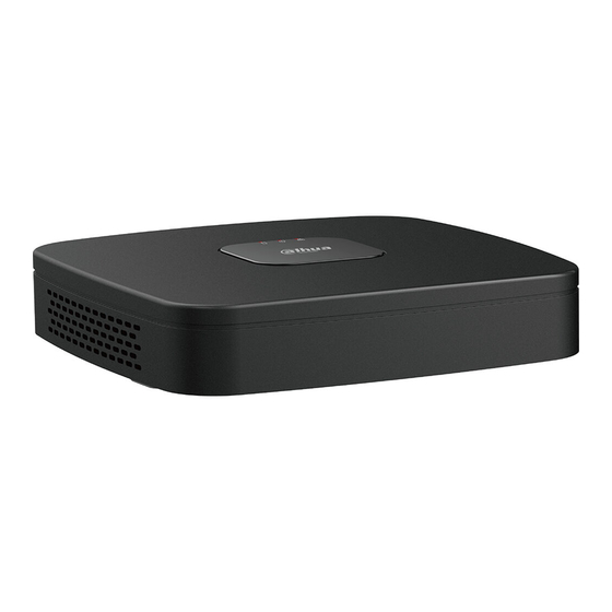
The following front panel and rear panel figures are for reference only. 2.1 Front Panel 2.1.1 N41C1P/N41C2P The figure is for reference only. The N41C1P/N41C2P front panel is shown as below. Figure 2-1 Front panel The N41C1P/N41C2P front panel is shown as below. - Page 21 User's Manual Figure 2-2 Front panel Table 2-1 Icons Name Function The red light becomes on when HDD is HDD status indicator light abnormal. The red light becomes on when the Power indicator light power connection is normal. Network status indicator The red light becomes on when the light network connection is abnormal.
-
Page 22: N42C1P/N42C2P/N42C3P/N52B5P/N54A4P/N54B3P/N54B5N
User's Manual Icon Name Function Power status indicator The blue light is on when the power POWER light connection is OK. Connect to peripheral USB storage device, USB port mouse and more. 2.1.2 N42C1P/N42C2P/N42C3P/N52B5P/N54A4P/N54B3P/N54B5N The figures are for reference only. The N42C1P/N42C2P/N42C3P/N52B5P/N54A4P/N54B3P/N54B5N series front panel is shown as below. -
Page 23: N82B2P/N82B3P/N82B5P
User's Manual Icon Name Function The blue light is on when the HDD status indicator light HDD malfunctions. The blue light is on when the Network status indicator light network connection is abnormal. The blue light is on when the POWER Power status indicator light power connection is normal. -
Page 24: N84B3P/N84B3N/N84B5N
User's Manual Figure 2-16 Front panel Table 2-6 Icons Icon Name Function HDD status indicator The blue light is on when the HDD malfunctions. light The blue light is on when the Network status indicator light network connection is abnormal. The blue light is on when the Power status indicator light power connection is OK. -
Page 25: N98A5N/N98A6N/N98A7N
User's Manual Figure 2-22 Front panel Table 2-10 Icons Icon Name Function The blue light is on when the HDD status indicator light HDD malfunctions. The blue light is on when the Network status indicator light network connection is abnormal. The blue light is on when the Power status indicator light power connection is normal. -
Page 26: Rear Panel
Name Power on-off button 2.2 Rear Panel 2.2.1 N41C1P/N41C2P The N41C1P/N41C2P series rear panel is shown as below. Figure 2-55 Rear panel The N41C1P/N41C2P series rear panel is shown as below. Figure 2-56 Rear panel The N41C1P/N41C2P series rear panel is shown as below. -
Page 27: N42C1P/N42C2P/N42C3P/N52B5P/N54A4P/N54B3P/N54B5N
It can connect to the monitor to view port analog video. Ground end. Power socket. ● For N41C1P/N41C2P: 12 VDC/2 A power. Power input port ● For NVR41-P-4KS2: 48 VDC/72 W power. ● For NVR41-8P-4KS2: 48 VDC/96 W power. - Page 28 User's Manual Figure 2-58 Rear panel The N42C1P series rear panel is shown as below. Figure 2-59 Rear panel The N42C2P series rear panel is shown as below. Figure 2-60 Rear panel The N42C3P series rear panel is shown as below. Figure 2-61 Rear panel Table 2-21 Rear panel description Name...
- Page 29 User's Manual Name Function Audio output port. It is to output the analog audio signal to the devices such as the sound box. ● Bidirectional talk output. MIC OUT Audio output port ● Audio output on 1-window video monitor. Audio output on 1-window video ●...
-
Page 30: Alarm Connection
User's Manual 2.3 Alarm Connection 2.3.1 Alarm Port The alarm port is shown as below. The following figure is for reference only. Figure 2-97 Alarm port Table 2-45 Alarm port description Icon Function ALARM1–ALARM16. The alarm becomes activated in the low 1–16 level. - Page 31 User's Manual 16) of the NVR. Connect the negative end (-) of the alarm input device to the ground end ) of the NVR. Figure 2-98 Alarm input port (1)
-
Page 32: Alarm Output Port
User's Manual Figure 2-99 Alarm input port (2) ● There are two alarm input types: NO/NC. ● When connect the ground port of the alarm device to the NVR, you can use any of the GND ports ( ● Connect the NC port of the alarm device to the alarm input port (ALARM) of the NVR. ●... -
Page 33: Alarm Relay Specifications
User's Manual 2.3.4 Alarm Relay Specifications Table 2-46 Alarm relay specifications Model: JRC-27F Material of the touch Silver Rated switch capacity 30 VDC 2 A, 125 VAC 1 A Maximum switch power 125 VAC, 160 W Rating (Resistance Load) Maximum switch voltage 250 VAC, 220 VDC Maximum switch currency Between touches with same... -
Page 34: Pc-End To The Device-End
User's Manual Figure 2-100 Enable two-way talk Step 5 At the device end, speak by the speaker or the pickup, and then you can get the audio from the earphone or sound box at the PC end. Figure 2-101 Device to PC 2.4.2 PC-end to the Device-end Device Connection 1. -
Page 35: Device Installation
User's Manual 3 Device Installation All the installation and operations here should conform to your local electric safety rules. 3.1 Device Installation Diagram Please see the following diagram to install the NVR. Figure 3-1 Installation flowchart... -
Page 36: Checking Unpacked Nvr
● Use the dedicated SATA HDD for monitoring recommended by the HDD manufacturer. ● You can see the Appendix for HDD space information and recommended HDD brand. 3.3.1 N41C1P/N41C2P Background Information Connect cable and then secure the HDD on the NVR if it is not convenient to connect the HDD data cable and power cable at first. - Page 37 User's Manual Figure 3-2 Lossen screws Step 2 Place the HDD in accordance with the four holes in the bottom. Figure 3-3 Aligh HDD Step 3 Turn the device upside down and then secure the screws firmly.
- Page 38 User's Manual Figure 3-4 Secure screws Step 4 Connect the HDD cable and power cable to the HDD and the mainboard respectively. Figure 3-5 Connect cables Step 5 Put the cover back and then fix the screws of the rear panel. The installation is complete.
-
Page 39: Cd-Rom Installation
User's Manual Figure 3-6 Put back the cover 3.4 CD-ROM Installation Procedure Step 1 Open the top cover and then remove the HDD bracket. Figure 3-37 Open the top cover Step 2 Take off the bottom of the HDD bracket and CD-ROM bracket. - Page 40 User's Manual Figure 3-38 Take out HDD bracket Figure 3-39 Take out CD-ROM bracket Step 3 Fix the CD-ROM bracket at the HDD bracket. Figure 3-40 Fix bracket Step 4 Install a pair of the CD-ROM bracket. Please make sure that the reverse side is secure too.
- Page 41 User's Manual Figure 3-42 Install bracket (reverse side) Step 5 Install SATA burner. Line up the SATA burner to the hole positions. Figure 3-43 Install SATA burner Step 6 Use screw driver to fix the screws. Figure 3-44 Fasten screws Step 7 Put the bracket back.
- Page 42 User's Manual Figure 3-45 Put bracket back Step 8 Connect the SATA cable and power wire. Figure 3-46 Connect cables Step 9 Secure the HDD bracket and put the top cover back.
-
Page 43: Connection Sample
User's Manual Figure 3-47 Put cover back 3.5 Connection Sample The following figures are for reference only and might differ from the actual product. 3.5.1 N41C1P/N41C2P Figure 3-48 Typical connection... -
Page 44: N42C1P/N42C2P/N42C3P/N52B5P/N54A4P/N54B3P/N54B5N
User's Manual 3.5.2 N42C1P/N42C2P/N42C3P/N52B5P/N54A4P/N54B3P/N54B5N Figure 3-52 Typical connection... -
Page 45: N42C1P/N42C2P/N42C3P/N52B5P/N54A4P/N54B3P/N54B5N
User's Manual 3.5.3 N42C1P/N42C2P/N42C3P/N52B5P/N54A4P/N54B3P/N54B5N Figure 3-53 Typical connection... -
Page 46: Starting The Device
User's Manual 4 Starting the Device Background Information ● For device security, connect the NVR to the power adapter first and then connect the device to the power socket. ● The rated input voltage matches the device power button. Make sure the power wire connection is OK. -
Page 47: Local Operations
User's Manual 5 Local Operations The following figures are for reference only. Slight difference might be found on the actual interface. 5.1 Initialization Background Information ● For first-time use, set a login password for the admin account (default user). ● We recommend setting password protection so that you can reset password in case you forgot. - Page 48 User's Manual Figure 5-1 Set password Table 5-1 Password parameters Parameter Description User By default, the user is admin. Password Enter the password for admin and then confirm the password. Confirm Password Enter the information that can remind you of the password. Password Hint On the login window, click to display the password hint.
- Page 49 User's Manual ● The pattern that you want to set must cross at least four points. ● If you do not want to configure the unlock pattern, click Skip. ● Once you have configured the unlock pattern, the system will require the unlock pattern as the default login method.
-
Page 50: Startup Wizard
User's Manual Table 5-2 Security question parameters Password Protection Description Mode Enter the linked email address. Enter an email address for password reset. If you forgot the Email Address password, enter the security code that you will get from this linked email address to reset the password of admin. - Page 51 User's Manual The number of network adapters might vary with models. Configure the IP address of the network adapter according to the actual connection situation. 1) Click Figure 5-5 Edit network adapter 2) Configure parameters. Table 5-3 Network parameters Parameter Description Network Mode ●...
- Page 52 User's Manual Parameter Description of the two network adapters is disconnected, the system network status is regarded as offline. ● Fault Tolerance : Two network adapters share one IP address. Normally only one network adapter is working. When this adapter fails, the other network adapter will start working automatically to ensure the network connection.
- Page 53 User's Manual To unbind NIC, on the TCP/IP page, click . The unbinding will take effect after the Device restarts. 3) On the TCP/IP page, configure DNS server. This step should be performed when you enable the domain name service. You can get DNS server address or manually enter it.
- Page 54 User's Manual ● The number of cameras that can be added to the NVR varies with models. ● The system supports adding camera through searching, manual add and batch add. This section uses adding by searching as an example. ● Initialize the camera before adding to the Device. 1) Click Search Device.
-
Page 55: Login
User's Manual For uninitialized cameras, the Device automatically initializes them before adding them. 3) Enable H.265 Auto Switch When H.265 Auto Switch is enabled, the video compression standard of added remote devices is switched to H.265 automatically. 4) Double-click a camera, or select a camera and then click Add to register it to the Added Device list. - Page 56 User's Manual Procedure Step 1 Right-click the live page, and then click the shortcut menu. ● If you have configured unlock pattern, the unlock pattern login window is displayed. Click Forgot Pattern to switch to password login. ● If you did not configure unlock pattern, the password login window is displayed. Figure 5-9 Unlock pattern login...
-
Page 57: Main Menu
User's Manual Figure 5-10 Password login Step 2 Draw unlock pattern, or enter password and then click OK. 5.4 Main Menu After login, right-click the live page, and then click Main Menu. - Page 58 User's Manual Figure 5-11 Main menu Table 5-4 Main menu description Description Click each tile to open the corresponding configuration page. Go back to live view. Point to the icon to view the current username. Log out of, restart, or shut down the Device. Click the icon to get the QR codes of mobile client and device SN.
-
Page 59: Quick Operation Bar
User's Manual 5.5 Quick Operation Bar You can click the icons on the main menu to go to the corresponding configuration page. After that, you can go to other function tiles or setting item through the quick operation bar. This section uses ALARM and CAMERA as examples to show how to quickly access other modules. -
Page 60: Live View
User's Manual Icon Description Go to the AUDIO page. Shortcut Icons on Setting Menu Click CAMERA to go to the CAMERA page. Figure 5-13 Quick operation bar (2) Table 5-6 Quick operation bar description (2) Icon Description Go to the CAMERA page. Go to the NETWORK page. -
Page 61: Live Page
User's Manual The number of window splits might vary depending on the model you are using. 5.6.1 Live Page On the live view page, you can view the live video of each channel. The corresponding channel displays date, time, and channel name after you overlay the corresponding information. -
Page 62: Live View Control Bar
User's Manual Icon Function Select view layout. Go to the previous screen. Go to the next screen. Enable tour function. The icon switches to If you close the tour or the triggered tour operation has canceled, the Device restores the previous preview video. Open the PTZ control panel. -
Page 63: Instant Playback
User's Manual ● Disable the navigation bar before using this function. ● The live view control bar is different depending on the model. Figure 5-15 Live view control bar Table 5-9 Live view control bar description Name Name Instant playback. Two-way talk. -
Page 64: Digital Zoom
User's Manual Figure 5-16 Instant playback ● Move the slider to choose the time you want to start playing. ● You can start, pause and close playback. ● The information such as channel name and recording status icon are shielded during instant playback and will not display until you exit playback. -
Page 65: Instant Backup
User's Manual When the image is in the enlarged status, you can drag the image toward any direction to view the other enlarged areas. Right-click to cancel zoom and go back to the original video image. Figure 5-17 Zoom 5.6.3.3 Instant Backup You can record the video of any channel and save the clip to a USB storage device. -
Page 66: Picture Search
User's Manual ● M: Main stream: Its bit streams are big and definition is high. It occupies large network bandwidth suitable for video wall security, storage and more. ● S: Sub stream: Its definition is low but occupies small network bandwidth. It is suitable for general security, remote connection and more. -
Page 67: Quick Pick
User's Manual Figure 5-19 Picture search results Related Operations ● Play video. Select the picture and then click to play back the video within 10 seconds before and after the snapshot. During playback, you can Click to pause. ◇ Click to stop. - Page 68 User's Manual You can adjust the searching area. Make sure that there are less than 30 targets in the selected area. Figure 5-20 Quick pick Step 3 Click OK. The search results are displayed. Figure 5-21 Search results Step 4 (Optional) Click Search Condition, change the search conditions, and then click Search.
-
Page 69: Shortcut Menu
User's Manual You can only select up to 8 targets for search. Figure 5-22 Search conditions Step 5 Hover over a search result to view the basic information including channel, start time, end time and target type. Double-click a result to play the video. You can select one or more search results and then click Backup to back up the results. - Page 70 User's Manual The shortcut menu is different for different models. Figure 5-23 Shortcut menu (1)
- Page 71 User's Manual Figure 5-24 Shortcut menu (2) Figure 5-25 Shortcut menu (3) Table 5-10 Shortcut menu description Function Description Main Menu Go to main menu. Search Search and play back videos or images. PTZ Control Open the PTZ control panel. For details, see "5.6.7 PTZ".
-
Page 72: Analytics+ Live View Mode
User's Manual Function Description View Configure the live view screen as a single-channel layout or 1/4/8/9/16/25/36 multi-channel layout. Set customized screen split mode and channels. For details, see Sequence "5.6.9 Sequence". Add Camera Add cameras to the Device. Wireless Pairing Quickly add IPCs. - Page 73 User's Manual Figure 5-26 Analytics+ live view Step 2 (Optional) Double-click the image on the right to play the corresponding video. Step 3 Click , and then select the face attributes that you want to display. You can select up to four attributes.
-
Page 74: Split Tracking
User's Manual Figure 5-27 Face vehicle properties Step 4 Click OK. The system can display four attributes at most. 5.6.6 Split Tracking You can track window split for a certain channel. Background Information This function is for select models only. Procedure Step 1 Right-click the live page, and then select Split Track. - Page 75 User's Manual Figure 5-28 Split track Step 2 Select a split mode. Figure 5-29 Split mode Split mode includes full screen, 1 main screen + 3 split screens and 1 main screen + 5 split screens. ● You can move the rectangles with color to adjust the videos displayed on split screens.
-
Page 76: Ptz
User's Manual Figure 5-30 Split display 5.6.7 PTZ PTZ is a mechanical platform that carries a camera and a protective cover and performs overall control remotely. A PTZ can move in both horizontal and vertical direction to provide all-around view to the camera. Before you control the PTZ, make sure the PTZ decoder and the NVR network connection is 5.6.7.1 PTZ Settings Background Information... - Page 77 User's Manual Figure 5-31 PTZ (local) Figure 5-32 PTZ (remote) Step 2 Configure parameters. Table 5-11 PTZ parameters Parameter Description Channel Select the channel that you want to connect the PTZ camera to.
-
Page 78: Ptz Control
User's Manual Parameter Description ● Local: Connect through RS-485 port. Type ● Remote: Connect through network by adding IP address of PTZ camera to the Device. Protocol Select the protocol for the PTZ camera such as PELCOD. Enter the address for PTZ camera. The default is 1. Address The entered address must be the same with the address configured on the PTZ camera;... - Page 79 User's Manual Parameter Description : Zoom out. Zoom : Zoom in. : Focus far. Focus : Focus near. : Image darker. Iris : Image brighter. PTZ movement Supports eight directions. Fast positioning button. ● Positioning: Click the icon, and the click any point on the live page.
-
Page 80: Configuring Ptz Functions
User's Manual ● The functions with buttons in gray are not supported by the system. ● Right-click once to return to the interface of PTZ basic control panel. Table 5-13 PTZ functions Icon Function Icon Function Preset Tour Flip Pattern Reset Click the AUX Config icon to open Scan... -
Page 81: Configuring Tours
User's Manual 5.6.7.3.2 Configuring Tours Procedure Step 1 On the expanded PTZ control panel, click Step 2 Click the Tour tab. Figure 5-36 Tour Step 3 In the Tour No. box, enter the value for the tour route. Step 4 In the Preset box, enter the preset value. -
Page 82: Configuring Autoscan
User's Manual Figure 5-37 Pattern Step 3 In the Pattern box, enter the value for pattern. Step 4 Click Start to perform the directions operations. You can also go to the PTZ Control Panel to perform the operations of adjusting zoom, focus, iris, and directions. Step 5 On the PTZ window, click End to complete the settings. -
Page 83: Using Ptz Functions
User's Manual 5.6.7.4 Using PTZ Functions After you have configured the PTZ settings, you can use the PTZ functions from the expanded PTZ control panel. Figure 5-39 Expanded PTZ control panel 5.6.7.4.1 Presets Procedure Step 1 On the expanded PTZ control panel, in the No. box, enter the value of the preset. Step 2 Click to call the preset. -
Page 84: Calling Autopan
User's Manual 5.6.7.4.5 Calling AutoPan Procedure Step 1 On the expanded PTZ control panel, click to start moving in horizontal direction. Step 2 Click again to stop moving. 5.6.7.4.6 Auxiliary Button On the expanded PTZ control panel, click In the Shortcut Aux list, select the option that corresponds to the applied protocol. In the Aux No. -
Page 85: Sequence
User's Manual Figure 5-41 Wireless pairing 5.6.9 Sequence Background Information You can configure the sequence of the channels displayed on the live page. Procedure Step 1 Right-click the live page, and then select Sequence. - Page 86 User's Manual ● After you select Sequence, the system automatically switches to the max split amount mode. ● The channel list on the Sequence panel displays the added camera channel number and channel name. means camera is online. means camera is offline.
- Page 87 User's Manual Figure 5-43 Channel number Step 3 Click Apply. After you change the channel sequence, click Cancel or right-click the live view page, the system prompts you whether to save the sequence change. ● Click OK to save current settings. ●...
-
Page 88: Fisheye
User's Manual 5.6.10 Fisheye This function is for some models only. 5.6.10.1 Fisheye De-warp on Live View Interface The fisheye camera (panoramic camera) has wide video of angle but its video is seriously distorted. The de-warp function can present the proper and vivid video suitable for human eyes. - Page 89 User's Manual ● The different installations modes have different de-warp modes. ● Some models support de-warp of 180° fisheye camera. 180° fisheye camera supports de-warp in wall mount mode only. Figure 5-46 Fisheye settings Table 5-14 Installation mode Installation mode Icon Description 360°...
-
Page 90: Fisheye De-Warp During Playback
User's Manual Installation mode Icon Description 1 panorama unfolding view +8 de warp windows Figure 5-47 De-warp You can adjust the color pane on the left pane or use your mouse to change the position of the small images on the right pane to realize fish eye de-warp. Operation: Use mouse to zoom in, zoom out, move, and rotate the image (Not for wall mount mode.) 5.6.10.2 Fisheye De-warp During Playback... -
Page 91: Shortcut Menu To Add Camera
User's Manual ● This function might collect the human temperature in the security video. ● This function is available on select models. Procedure Step 1 Go to Main Menu > DISPLAY > Display to enable the temperature test function. Step 2 On the live page, click any position on the thermal channel video. -
Page 92: Smart Tracking
User's Manual Figure 5-49 Add icon Step 2 Click "+", and then configure the parameters to add the remote device. For details, see "5.7.2 Adding Remote Devices". 5.6.13 Smart Tracking Track targets manually or automatically. This function is only available on the multi-sensor panoramic camera + PTZ camera. - Page 93 User's Manual ● When you connect a camera to the NVR via PoE port, NVR automatically initializes the camera. The camera adopts NVR current password and email information by default. ● When you connect a camera to the NVR via PoE port after NVR is upgraded to the new version, the NVR might fail to initialize the camera.
- Page 94 User's Manual Figure 5-51 Password 2) Enter the password and then confirm it. For your device security, we recommend you create a strong password according to the password strength indication and change your password regularly. 3) Click Next.
- Page 95 User's Manual Figure 5-52 Password protection 4) Enter your email address, and then click Next. The email address is used to receive the security code for password resetting. If you do not want to enter email information, cancel the selection of the checkbox and then click Next or Skip.
- Page 96 User's Manual ● When you are changing IP addresses of several devices at the same time, enter incremental value. The system can add the fourth decimal digit of the IP address one by one to automatically allocate the IP addresses. ●...
-
Page 97: Adding Remote Devices
User's Manual Figure 5-54 Device initialization Step 8 Click Finished. 5.7.2 Adding Remote Devices Add remote devices to the NVR to receive, store, and manage the video streams of the remote device. Before adding the remote devices, make sure that the devices have been initialized. 5.7.2.1 Adding Cameras from Search Background Information Search for the remote devices that are on the same network with the NVR, and then add the... - Page 98 User's Manual The remote devices found are displayed at the upper pane. Devices already added are not included in the searched results. Figure 5-55 Search device ● For cameras accessed through private protocol, you can click LIVE and then enter the username and password to play live video. ●...
-
Page 99: Adding Cameras Manually
User's Manual For uninitialized remote devices, the NVR automatically initializes them before adding them. Step 4 (Optional) Enable H.265 Auto Switch. When H.265 Auto Switch is enabled, the video compression standard of added remote devices is switched to H.265 automatically. Step 5 Double-click a remote device, or select a remote device and then click Add to register it to the Added Device list. - Page 100 User's Manual We recommend this method when you want to add only a few remote devices and know their IP addresses, usernames and passwords. Procedure Step 1 Select Main Menu > CAMERA > Camera List > Camera List. Step 2 (Optional) Enable H.265 Auto Switch.
-
Page 101: Importing Cameras
User's Manual Parameter Description RTSP Port Enter the RTSP port number. The default value is 554. HTTP Port Enter the HTTP port number. The default value is 80. TCP Port The default value is 37777. You can enter the value as needed. Username Enter the username of the remote device. -
Page 102: Changing Ip Address Of Remote Device
User's Manual Figure 5-57 Backup encryption 2) Cancel the selection of the On checkbox to disable backup encryption, and then click OK. ● If Backup Encryption is enabled, the file format is .backup. ● If Backup Encryption is disabled, the file format is .csv. Keep unencrypted files well to avoid data leakage. -
Page 103: Changing Ip Address Of Connected Remote Device
User's Manual You can change the IP address only when the camera is online. 5.7.3.1 Changing IP Address of Connected Remote Device Procedure Step 1 Select Main Menu > CAMERA > Camera List > Camera List. Step 2 On the Added Device list, double-click a remote device or click Step 3 Change the IP address. - Page 104 User's Manual Figure 5-58 Image Step 2 Select a channel and then configure parameters. The parameters might vary depending on the camera model. Table 5-16 Image parameters Parameter Description There are three configuration files. The system has configured Profile the corresponding parameters for each file. You can select according to your actual situation.
- Page 105 User's Manual Parameter Description Adjust the sharpness of image edge. The bigger the value is, the Sharpness more obvious the image edge is. Adjust image brightness and enhance the image dynamic display Gamma range. The bigger the value is, the brighter the video is. Switch the left and right sides of the video image.
- Page 106 User's Manual Parameter Description You can set camera backlight mode. ● SSA: In the backlight environment, the system can automatically adjust image brightness to clearly display the object. ● BLC: Default: The device performs automatic exposures ◇ according to the environment situation to make the darkest area of the video clear.
-
Page 107: Configuring Overlay Settings
User's Manual 5.7.5 Configuring Overlay Settings You can set parameters for overlay and private masking. 5.7.5.1 Overlay Background Information You can add the information of time and channel in the live view interface. Procedure Step 1 Select Main Menu > CAMERA > Overlay > Overlay. Step 2 Select a channel and then configure parameters. -
Page 108: Configuring Encoding Settings
User's Manual Figure 5-59 Privacy masking Step 2 Select a channel. Step 3 Click to enable privacy masking. Step 4 Click Add, select the masking type and color, and then draw mosaic or color blocks in the image as needed. A masking block appears on the video image. - Page 109 User's Manual Figure 5-60 Audio/video Step 2 Select a channel and then configure parameters. The parameters for main stream and sub stream are different. Some models support three streams: main stream, sub stream 1, sub stream 2. Table 5-18 Audio/video parameters Parameter Description ●...
- Page 110 User's Manual Parameter Description Select the encoding mode. ● H.265: Main profile encoding. This setting is recommended. ● H.264H: High profile encoding. Low bit stream with high definition. Compression ● H.264: Main profile encoding. ● H.264B: Baseline profile encoding. This mode requires higher bit stream compared with other modes for the same definition.
-
Page 111: Snapshot
User's Manual Figure 5-61 More settings Step 4 Configure audio compression parameters. Table 5-19 Audio compression parameters Parameter Description This function is enabled by default for main stream. You need to Audio manually enable it for sub stream. Once this function is enabled, the recorded video file is composite audio and video stream. - Page 112 User's Manual Figure 5-62 Snapshot Step 2 Configure parameters. Table 5-20 Snapshot parameters Parameter Description Manual Snapshot Select the number of snapshots that you want to take each time. Channel Select the channel that you want to configure the settings for. ●...
-
Page 113: Modifying Channel Name
User's Manual 5.7.7 Modifying Channel Name Background Information You can customize channel name. Procedure Step 1 Select Main Menu > CAMERA > Camera Name. Figure 5-63 Camera name Step 2 Modify a channel name. ● You can only change the name of the camera connected via the private protocol. ●... -
Page 114: Updating Remote Devices
User's Manual Figure 5-64 PoE Step 2 (Optional) Set Enhancement Mode to On or Off. When enhancement mode is enabled, the transmission distance of the PoE port will be extended. 5.7.9 Updating Remote Devices Background Information You can update the firmware of the connected network camera through online update or file update. -
Page 115: Viewing Remote Device Information
User's Manual Figure 5-65 Update Step 2 Update the firmware of the connected remote device. ● Online update. 1. Select a remote device and then click Manual Check .The system checks for available updates. 2. Select a remote device that has an update available for it, and then click Online Update. -
Page 116: Firmware
User's Manual Select Main Menu > CAMERA > Camera List > Device Status. Figure 5-66 Device status Table 5-21 Parameters of device status Icon Description Icon Description IPC works properly. IPC is not supported. Alarm. Video loss. 5.7.10.2 Firmware You can view the IP address, manufacturer, type, and system version of the connected remote device. -
Page 117: Recording Management
User's Manual Figure 5-67 Firmware 5.8 Recording Management 5.8.1 Recording Schedule After you set the recording schedule for videos and snapshots, the Device can automatically record videos and snapshots at the scheduled time. 5.8.1.1 Configuring Video Recording Schedule Background Information After you set the schedule for videos, the Device will record videos according to the period you set. - Page 118 User's Manual Figure 5-68 Video schedule Step 2 Configure the parameters. Table 5-22 Video schedule parameters Parameter Description Channel Select a channel to record a video. Enter the amount of time that you want the pre-recording to Pre-record last. A recording will be made prior to the event.
- Page 119 User's Manual Parameter Description If there are several HDDs installed to the Device, you can set one of the HDDs as the redundant HDD to save the recorded files into different HDDs. If one of the HDDs becomes damaged, you can find the backup on the other HDD.
- Page 120 User's Manual Figure 5-69 Period Step 3 Set one or more recording types from General, Motion (motion detection), Alarm, M&A (motion detection and alarm), Intelligent and Alarm. Figure 5-70 Recording type Step 4 Set recording period. If you have added a holiday, you can set the recording period for the holiday. Figure 5-71 Set record period ●...
- Page 121 User's Manual You can define the period for all the days simultaneously. Define for several days of a week: Click before each day one by one. ◇ The icon switches to . You can define the period for the selected days simultaneously.
-
Page 122: Configuring Snapshot Schedule
User's Manual Figure 5-73 Set period by editing 2. Set the recording type for each period. There are six periods for you to set for each day. ◇ Under Copy to, select All to apply the settings to all the days of the week, ◇... -
Page 123: Configuring Recording Mode
User's Manual Figure 5-74 Snapshot Step 2 Select a channel to set schedule snapshot. Step 3 Set a recording type. Figure 5-75 Recording type Step 4 Set snapshot period. For details, see Step4 in "5.8.1.1 Configuring Video Recording Schedule". Step 5 Click Apply. - Page 124 User's Manual You need to have storage authorities to use the Manual recording mode. Procedure Step 1 Right-click the live page, and then select Main Menu > STORAGE > Record. Figure 5-76 Recording mode Step 2 Configure parameters. Table 5-23 Recording mode parameters Parameter Description Displays all the connected channels.
-
Page 125: Search And Playback
User's Manual 5.8.2 Search and Playback 5.8.2.1 Search Page You can search for and play back the recorded files on the NVR. Select Main Menu > SEARCH, or right-click on the live view page and then select Search. The following figure is for reference only. Figure 5-77 Search Table 5-24 Search page description Function... - Page 126 User's Manual Function Description Click to clip the recording file and then save the Clip footage. See "5.8.2.4 Clipping Videos" for details. Backup Click to back up recordings. Display the type and time period of the current recorded video. ● In the 4-channel layout, 4 time bars are displayed. In other view layouts, only 1 time bar is displayed.
-
Page 127: Playback
User's Manual Function Description Click the date that you want to search for. Calendar The dates with recordings or snapshots have a small solid circle under the date. ● In the Camera Name list, select one or more channels that you want to play back. ●... - Page 128 User's Manual Step 2 Select From R/W Disk or From I/O Device. ● From R/W Disk: Search for recorded files on the HDD of the Device. Figure 5-78 Search from R/W disk ● From I/O Device: Search for recorded files from external storage device. Click Browse, select the storage path of the recorded video file that you want to play.
- Page 129 User's Manual Icon Function Fast forward In playback mode, click to realize various fast play modes such as fast play 1,fast play 2 and more. Adjust the volume of the playback. Smart search. See "5.8.2.3 Smart Search Playback" for detailed information. Smart motion detection.
-
Page 130: Smart Search Playback
User's Manual 5.8.2.3 Smart Search Playback Background Information This function is for some models only. During the playback process, the system can analyze the motion detection zone in the scene and give the analysis result. Make sure that motion detection has been enabled in Main Menu > ALARM > Video Detection >... -
Page 131: Backing Up
User's Manual Figure 5-81 Clip 5.8.2.5 Backing Up Background Information You can back up recorded videos, images, or video clips to a USB storage device. Procedure Step 1 Select the files that you want to back up. ● Videos or images. Click at the lower-right corner of the search page, and then on the file list, select the files for backup. -
Page 132: File List
User's Manual ● You can cancel the selection of the files that you do not want to back up. ● Select Combine Video to merge several videos into one. 5.8.2.6 File List On the search page, select a channel, and then click to view the file list. -
Page 133: Recording Information
User's Manual The system can play back previous N seconds before the tagged time if there is a video at that point. Otherwise, the system plays back as much as there is. Managing Tags On the tag list, click Figure 5-83 Tag management ●... -
Page 134: Analytics
User's Manual Figure 5-84 Recording information 5.9 Analytics+ Analytics+ detection is to process and analyze the image and extract the key information, and then compare the key information with the preset detection rule. An alarm is triggered when the detected behavior matches the detection rule. The following figures are for reference only and might differ from the actual situation. -
Page 135: Smart Plan
User's Manual ● Some models support Analytics+ by camera only. ● The Analytics+ functions might vary with models. ● Different Analytics+ functions might conflict with each other. You cannot enable two conflicting Analytics+ functions for the same channel. 5.9.2 Smart Plan Background Information To use Analytics+ by camera for face detection, Face Detection+ and other detection functions, you need to enable the corresponding smart plan first. -
Page 136: Face Detection
User's Manual Step 3 Click the icon that represents the smart plan to enable it. The icon becomes highlighted. If the channel is connected to a PTZ camera, you can set smart plans separately for each preset point. Figure 5-86 Smart plan (PTZ) Step 4 Click Apply. - Page 137 User's Manual Procedure Step 1 Select Main Menu > Analytics+ > Parameters > Face Detection. Figure 5-87 Face detection Step 2 Select a channel, and then select Analytics+ by Reorder or Analytics+ by camera as Type. When Analytics+ by camera is selected, you can enable Face Enhancement to improve face detection efficiency.
-
Page 138: Analytics+ Search (Face Detection)
User's Manual 5.9.3.3 Analytics+ Search (Face Detection) Background Information You can search for the detected faces and play back related recordings. Procedure Step 1 Select Main Menu > Analytics+ > Analytics+ Search > Face Detection. Figure 5-88 Face search Step 2 Select the channel, enter the start time and end time, and select the attributes. - Page 139 User's Manual For privacy reason, the human faces in the image are intentionally blurred. The actual image is clear. Figure 5-89 Search results Related Operations ● Play related video. Click a face and then click . The system plays back the video around the snapshot time. ●...
-
Page 140: Face & Body Detection
User's Manual Figure 5-90 Add face image to database 5.9.4 Face & Body Detection After enabling face & body detection, you can view the face and body snapshots and related attributes on the live page. 5.9.4.1 Enabling Smart Plan To use Analytics+ by camera, you need to enable the smart plan first. For details, see "5.9.2 Smart Plan". -
Page 141: Analytics+ Search (Face & Body Detection)
User's Manual Figure 5-91 Face and body detection Step 2 Select a channel, and then click to enable the function. Step 3 Enable Face & Body Image Enhancement to improve detection efficiency. Step 4 Configure target filters. You can configure two target filters (maximum size and minimum size). The system triggers an alarm when the size of detected target is between the maximum size and the minimum size. -
Page 142: Enabling Smart Plan
User's Manual 5.9.5.1 Enabling Smart Plan To use Analytics+ by camera, you need to enable the smart plan first. For details, see "5.9.2 Smart Plan". 5.9.5.2 Creating Face Database Create face databases to manage face images for Face Detection+. 5.9.5.2.1 Creating Local Face Databases You can create face databases on the Device to manage face images for Face Detection+ by Device. -
Page 143: Creating Remote Face Databases
User's Manual Figure 5-93 Add database Step 3 Select Normal Database from the Type list, and then enter database name. Step 4 Click OK. 5.9.5.2.2 Creating Remote Face Databases The Device can get face databases from the remote devices, and also allows creating face databases for remote devices. -
Page 144: Adding Images To Face Database
User's Manual You can create only one passerby database. Figure 5-94 Add database Step 3 Select Passerby Database from the Type list, and then configure other parameters. Table 5-26 Passerby database parameters Parameter Description Name Enter a name for the passerby database. Configure the number of images that the database can Number of Images contain. - Page 145 User's Manual Step 2 Click of the database that you want to configure. Figure 5-95 Databases details Step 3 Click Register. Figure 5-96 Register Step 4 Click to add a face image.
- Page 146 User's Manual Figure 5-97 Browse Step 5 Select a face image and then enter the registration information. Step 6 Click OK. The system prompts the registration is successful. Step 7 On the Details page, click Search. The system prompts modeling is successful. If the system prompts modeling is in process, wait a while and then click Search again.
-
Page 147: Adding Face Images In Batches
User's Manual Select one or more face images, and then click Delete. 5.9.5.3.2 Adding Face Images in Batches Background Information The system supports batch add if you want to import several human face image at the same time. Procedure Step 1 Give a name to the face picture by referring to the following table. -
Page 148: Configuring Face Detection
User's Manual Related Operations ● Edit registration information. Click to modify the registration information. ● Model face images. The face images are modeled automatically after added to face database. You can also model face images manually. On the Database Config page, select a database, and then click Modeling to model all ◇... - Page 149 User's Manual Figure 5-99 Analytics+ by recorder Step 3 Click Setting next to Schedule to configure arming periods. The corresponding alarm actions are linked by the alarm events triggered during armed period. Step 4 Arm target face database. ● General Alarm: The alarm is triggered when the similarity of detected faces reaches the defined value.
-
Page 150: Configuring Analytics+ By Camera
User's Manual Figure 5-100 Stranger alarm (Analytics+ by recorder) 1. Select Stranger Alarm in Analytics+ Mode. 2. Click enable the function. 3. Configure the alarm linkage actions. For details on alarm linkage, see Table 5-43. Step 5 Click Apply. 5.9.5.4.2 Configuring Analytics+ by camera Prerequisites Make sure the connected camera supports Face Detection+. -
Page 151: Analytics+ Search (Face Detection+)
User's Manual Figure 5-101 Analytics+ by camera Step 3 Enable Face Enhancement to make the faces displayed more clear. Step 4 Click Rule to draw areas to filter the target. You can configure two target filters (maximum size and minimum size). When the target is smaller than the minimum size or larger than the maximum size, no alarms will be activated. - Page 152 User's Manual Figure 5-102 Search by attributes Step 2 Select the channel and set the parameters including start time, end time, gender, age, glasses, beard, mask, name and similarity. Step 3 Click Search. The faces in the image are intentionally blurred for privacy protection. The actual images are clear.
-
Page 153: Search By Image
User's Manual During playback, you can: Click to pause. ◇ Click to stop. ◇ Click to display Analytics+ rule. The icon changes to ◇ ● Add tags. Select one or more images, and then click Add Tag. ● Lock. Select one or more images, and then click Lock. The locked files will not be overwritten. ●... -
Page 154: Report Query
User's Manual start time, end time, gender, age, glasses, beard, mask, and similarity. Step 4 Click Search. The search results are displayed. Related Operations ● Play back video. Click an image, and then click to play back the related video. During playback, you can: Click to pause. -
Page 155: Ivs
User's Manual Figure 5-105 Face statistics Step 2 Select the report type, start time and end time, and then click Search. Related Operations ● Switch chart type. Click Bart Chart or Line Chart to switch the chart type. ● Export. Select file type, and then click Export to export the report in picture or csv format. -
Page 156: Configuring Ivs
User's Manual 5.9.6.2 Configuring IVS 5.9.6.2.1 Tripwire Background Information When the detection target crosses the warning line along the set direction, the system performs an alarm linkage action. Procedure Step 1 Select Main Menu > Analytics+ > Parameters > IVS. Figure 5-106 IVS Step 2 Select channel and Analytics+ type. - Page 157 User's Manual Figure 5-107 Tripwire (Analytics+ by camera) Figure 5-108 Tripwire (Analytics+ by recorder) 2) Click to draw the minimum size or maximum size to filter the target. The system triggers an alarm only when the size of detected target is between the maximum size and the minimum size.
-
Page 158: Intrusion
User's Manual Table 5-28 Tripwire parameters Parameter Description Name Customize the rule name. Direction Set the tripwire direction, including A→B, B→A and A ↔ B. Click and then select effective target. With Human and Motor Vehicle selected by default, the system automatically Target Filter identifies the person and motor vehicle appeared within the monitoring range. - Page 159 User's Manual Procedure Step 1 Select Main Menu > Analytics+ > Parameters > IVS. Figure 5-110 IVS Step 2 Select channel and Analytics+ type. Step 3 Click Add to add a rule. Step 4 On the Type list, select Intrusion. Step 5 Draw the detection rule.
- Page 160 User's Manual Figure 5-111 Intrusion (Analytics+ by camera) Figure 5-112 Intrusion (Analytics+ by recorder) 2) Click to draw the minimum size or maximum size to filter the target. The system triggers an alarm only when the size of detected target is between the maximum size and the minimum size.
-
Page 161: Abandoned Object Detection
User's Manual Table 5-29 Intrusion parameters Parameter Description Name Customize the rule name. Action Set the intrusion action, including appear and crossing area. Direction Set the direction to cross the area, including enter, exit and both. Click and then select effective target. With Human and Motor Target Filter Vehicle selected by default, the system automatically identifies the person and motor vehicle appeared within the monitoring range. - Page 162 User's Manual Procedure Step 1 Select Main Menu > Analytics+ > Parameters > IVS. Figure 5-114 IVS Step 2 Select channel and Analytics+ type. Step 3 Click Add to add a rule. Step 4 On the Type list, select Abandoned Object. Step 5 Draw the detection rule.
- Page 163 User's Manual Figure 5-115 Abandoned object rule 2) Click to draw the minimum size or maximum size to filter the target. The system triggers an alarm only when the size of detected target is between the maximum size and the minimum size. 3) Configure parameters.
-
Page 164: Fast Moving
User's Manual Figure 5-116 Schedule and alarm linkage 1) Click 2) Click Setting next to Schedule to configure the alarm period. The system performs linkage actions only for alarms during the arming period. ● On the time line, drag to set the period. ●... - Page 165 User's Manual Figure 5-117 IVS Step 2 Select channel and Analytics+ type. Step 3 Click Add to add a rule. Step 4 On the Type list, select Fast Moving. Step 5 Draw the detection rule. 1) Click to draw a rectangle on the security video image. Right-click the image to stop drawing.
- Page 166 User's Manual Figure 5-118 Fast moving 2) Click to draw the minimum size or maximum size to filter the target. The system triggers an alarm only when the size of detected target is between the maximum size and the minimum size. 3) Configure parameters.
-
Page 167: Parking
User's Manual Figure 5-119 Schedule and alarm linkage 1) Click 2) Click Setting next to Schedule to configure the alarm period. The system performs linkage actions only for alarms during the arming period. ● On the time line, drag to set the period. ●... - Page 168 User's Manual Figure 5-120 IVS Step 2 Select channel and Analytics+ type. Step 3 Click Add to add a rule. Step 4 On the Type list, select Parking. Step 5 Draw the detection rule. 1) Click to draw a rectangle on the security video image. Right-click the image to stop drawing.
- Page 169 User's Manual Figure 5-121 Parking 2) Click to draw the minimum size or maximum size to filter the target. The system triggers an alarm only when the size of detected target is between the maximum size and the minimum size. 3) Configure parameters.
-
Page 170: Crowd Gathering
User's Manual Figure 5-122 Schedule and alarm linkage 1) Click 2) Click Setting next to Schedule to configure the alarm period. The system performs linkage actions only for alarms during the arming period. ● On the time line, drag to set the period. ●... - Page 171 User's Manual Figure 5-123 IVS Step 2 Select channel and Analytics+ type. Step 3 Click Add to add a rule. Step 4 On the Type list, select Crowd Gathering Estimation. Step 5 Draw the detection rule. 1) Click to draw a rectangle on the security video image. Right-click the image to stop drawing.
- Page 172 User's Manual Figure 5-124 Crowd gathering 2) Click to draw the minimum size or maximum size to filter the target. The system triggers an alarm only when the size of detected target is between the maximum size and the minimum size. 3) Set parameters.
-
Page 173: Missing Object Detection
User's Manual Figure 5-125 Schedule and alarm linkage 1) Click 2) Click Setting next to Schedule to configure the alarm period. The system performs linkage actions only for alarms during the arming period. ● On the time line, drag to set the period. ●... - Page 174 User's Manual Figure 5-126 IVS Step 2 Select channel and Analytics+ type. Step 3 Click Add to add a rule. Step 4 On the Type list, select Missing. Step 5 Draw the detection rule. 1) Click to draw a rectangle on the security video image. Right-click the image to stop drawing.
- Page 175 User's Manual Figure 5-127 Missing object 2) Click to draw the minimum size or maximum size to filter the target. The system triggers an alarm only when the size of detected target is between the maximum size and the minimum size. 3) Configure parameters.
-
Page 176: Loitering Detection
User's Manual Figure 5-128 Schedule and alarm linkage 1) Click 2) Click Setting next to Schedule to configure the alarm period. The system performs linkage actions only for alarms during the arming period. ● On the time line, drag to set the period. ●... - Page 177 User's Manual Figure 5-129 IVS Step 2 Select channel and Analytics+ type. Step 3 Click Add to add a rule. Step 4 On the Type list, select Loitering Detection. Step 5 Draw the detection rule. 1) Click to draw a rectangle on the security video image. Right-click the image to stop drawing.
- Page 178 User's Manual Figure 5-130 Loitering detection 2) Click to draw the minimum size or maximum size to filter the target. The system triggers an alarm only when the size of detected target is between the maximum size and the minimum size. 3) Configure parameters.
-
Page 179: Analytics+ Search (Ivs)
User's Manual Figure 5-131 Schedule and alarm linkage 1) Click 2) Click Setting next to Schedule to configure the alarm period. The system performs linkage actions only for alarms during the arming period. ● On the time line, drag to set the period. ●... -
Page 180: Stereo Analysis
User's Manual Figure 5-132 IVS search Step 2 Select a channel, start time, end time, event type, and then click Search. The search results are displayed. Related Operations ● Play back video. Click an image, and then click to play back the related video. During playback, you can: Click to pause. -
Page 181: Enabling Smart Plan
User's Manual people stay detection. ● This function requires access to a camera that supports stereo behavior analysis. ● Stereo analysis and IVS are mutually exclusive and cannot be enabled at the same time. 5.9.7.1 Enabling Smart Plan To use Analytics+ by camera, you need to enable the smart plan first. For details, see "5.9.2 Smart Plan". -
Page 182: Fall Detection
User's Manual Figure 5-133 Schedule and alarm linkage 1) Click 2) Click Setting next to Schedule to configure the alarm period. The system performs linkage actions only for alarms during the arming period. ● On the time line, drag to set the period. ●... - Page 183 User's Manual Table 5-37 Parameters of fall detection Parameter Description Name Customize the rule name. Sensitivity Set alarm sensitivity. Duration Set the minimum time of triggering an alarm when people fall. Set repeat alarm time. If the alarm-triggering event continues, an Repeat Alarm Time alarm will be triggered again when repeat alarm time passed.
-
Page 184: Violence Detection
User's Manual 5.9.7.2.3 Violence Detection When the target in the detection region has large body movements such as smashing and fighting, an alarm will be triggered. Procedure Step 1 Select Main Menu > Analytics+ > Parameters > Stereo Analysis. Step 2 Select a channel and then click Add. -
Page 185: People No. Exception Detection
User's Manual 3) Configure alarm linkage. For details, see Table 5-43. 4) Click Apply. Step 6 Click Apply. 5.9.7.2.4 People No. Exception Detection When the system detects an abnormal number of people in the same detection area, an alarm will be triggered. Procedure Step 1 Select Main Menu >... -
Page 186: People Stay Detection
User's Manual Figure 5-136 Schedule and alarm linkage 1) Click 2) Click Setting next to Schedule to configure the alarm period. The system performs linkage actions only for alarms during the arming period. ● On the time line, drag to set the period. ●... -
Page 187: Analytics+ Search (Stereo Analysis)
User's Manual Table 5-40 Parameters of people stay detection Parameter Description Name Customize the rule name. Sensitivity Set alarm sensitivity. Set low long people stay in the detection area until an alarm is Duration triggered. Set repeat alarm time. If the alarm-triggering event continues, an Repeat Alarm Time alarm will be triggered again when repeat alarm time passed. -
Page 188: Video Metadata
User's Manual Procedure Step 1 Select Main Menu > Analytics+ > Analytics+ Search > Stereo Analysis. Figure 5-138 Stereo analysis search Step 2 Select a channel, start time, end time, event type, and then click Search. The search results are displayed. Related Operations ●... -
Page 189: Enabling Smart Plan
User's Manual and non-motor vehicle. Once a target is detected, an alarm is triggered. 5.9.8.1 Enabling Smart Plan To use Analytics+ by camera, you need to enable the smart plan first. For details, see "5.9.2 Smart Plan". 5.9.8.2 Configuring Video Metadata When a metadata alarm is triggered, the system links the corresponding camera to record videos and logs and take snapshots. - Page 190 User's Manual Analytics+ by recorder is available on select models. Step 3 Click Add to add a rule. Step 4 Select Enable and then set Type to People Detection, Non-motor Vehicle Detection or Motor Vehicle Detection. Step 5 Draw detection rule. 1) Click , and then draw a detection area on the video image.
-
Page 191: Analytics+ Search (Video Metadata)
User's Manual 5.9.8.3 Analytics+ Search (Video Metadata) You can search for the video metadata detection results and play back related videos. 5.9.8.3.1 Human Detection Procedure Step 1 Select Main Menu > Analytics+ > Analytics+ Search > Human Detection. Figure 5-141 Human detection Step 2 Select a channel, start time, end time, and set corresponding parameters. -
Page 192: Motor Vehicle Detection
User's Manual For privacy protection, the faces are intentionally blurred. Figure 5-142 Search results Related Operations ● Play back video. Click an image, and then click to play back the related video. During playback, you can: Click to pause. ◇ Click to stop. - Page 193 User's Manual This function is available on select models. Procedure Step 1 Select Main Menu > Analytics+ > Analytics+ Search > Motor Vehicle Detection. Figure 5-143 Motor vehicle detection Step 2 Select a channel and then set parameters. ● The system supports fuzzy search of plate numbers. ●...
-
Page 194: Non-Motor Vehicle Detection
User's Manual Click to display Analytics+ rule. The icon changes to ◇ ● Add tags. Select one or more images, and then click Add Tag. ● Lock. Select one or more images, and then click Lock. The locked files will not be overwritten. ●... -
Page 195: Report Query
User's Manual Step 3 Click Search. Figure 5-145 Search results Related Operations ● Play back video. Click an image, and then click to play back the related video. During playback, you can: Click to pause. ◇ Click to stop. ◇ Click to display Analytics+ rule. -
Page 196: Anpr
User's Manual ● The statistics might be overwritten when the storage space runs out. Back up in time. ● When you restore the Device to factory settings, all the data except data in the external storage device will be cleared. You can clear the data in the external storage device through formatting or other methods. -
Page 197: Adding Vehicle Blocklist And Allowlist
User's Manual 5.9.9.1 Adding Vehicle Blocklist and Allowlist Background Information To facilitate vehicle management, you can add the plate numbers to the blocklist or allowlist. The system can compare the detected plate information with the plate on the blocklist and allowlist and then trigger the corresponding alarm linkage. -
Page 198: Configuring Anpr
User's Manual ● Import and export plate information. Import: Click Import, select the corresponding file, and then click Browse to import the ◇ file. Export: Click Export, select the file storage path and then click Save. ◇ ● Delete plate information. Delete one by one: Click the of the corresponding plate number. -
Page 199: Analytics+ Search (Anpr)
User's Manual Step 4 Click General (default), Blocklist or Allowlist tab. Before enabling the blocklist alarm or allowlist alarm, you need to add the corresponding plate information. ● General: The system triggers an alarm when it detects any plate number. ●... -
Page 200: Report Query
User's Manual Figure 5-149 Crowd distribution Step 2 Select a channel and then click next to Enable. Step 3 Configure parameters. Table 5-41 Crowd distribution parameters Parameter Description Crowd Density (Global) Click and then configure the density threshold. Crowd Density Alarm Tracking After an alarm occurs, the system tracks the target automatically. -
Page 201: People Counting
User's Manual ● The statistics might be overwritten when the storage space runs out. Back up in time. ● When you restore the Device to factory settings, all the data except data in the external storage device will be cleared. You can clear the data in the external storage device through formatting or other methods. - Page 202 User's Manual Figure 5-150 People counting Step 2 Select a channel and then click Add. Step 3 Select the Enable checkbox and then set Type to People Counting. Step 4 Draw people counting rule. 1) Click to draw people counting rule. Right-click the image to stop drawing. Figure 5-151 People counting rule 2) Customize the rule name and then select direction.
-
Page 203: Configuring In Area No
User's Manual Table 5-42 People counting parameters Parameter Description ● Select Enter No., and then the number of people entering the detection zone will be displayed on the live page. ● Select Exit No., and then the number of people leaving the detection zone will be displayed on the live page. -
Page 204: Queuing
User's Manual Step 2 Select a channel and then click Add. Step 3 Select the Enable checkbox and then set Type to In Area No. Step 4 Draw people counting rule. 1) Click to draw a rule. Right-click the image to stop drawing. 2) Configure the parameters. -
Page 205: Report Query
User's Manual 5.9.11.5 Report Query Background Information You can search for and export the people counting statistics. ● The statistics might be overwritten when the storage space runs out. Back up in time. ● When you restore the Device to factory settings, all the data except data in the external storage device will be cleared. -
Page 206: Enabling Smart Plan
User's Manual 5.9.12.1 Enabling Smart Plan To use Analytics+ by camera, you need to enable the smart plan first. For details, see "5.9.2 Smart Plan". 5.9.12.2 Configuring Heat map Background Information Heat map technology can monitor the active objects distribution status on the specified zone during a period of time, and use different colors to display on the heat map. -
Page 207: Report Query
User's Manual Figure 5-156 Schedule Step 4 Click Apply. 5.9.12.3 Report Query You can search for and export the heat map report of general and fisheye cameras. 5.9.12.3.1 General Procedure Step 1 Select Main Menu > Analytics+ > Report Query > Heat Map > General. Figure 5-157 General Step 2 Select the channel, start time, and end time. -
Page 208: Fisheye
User's Manual 5.9.12.3.2 Fisheye Procedure Step 1 Select Main Menu > Analytics+ > Report Query > Heat Map > Fisheye. Figure 5-158 Fisheye Step 2 Set channel, type and period, and then click Search. Step 3 Click Export to export the heat map. 5.9.13 SMD You can use SMD (Smart Motion Detection) to detect humans and vehicles in the video, and store the detection results in structured storage for fast retrieval. - Page 209 User's Manual Figure 5-159 SMD Step 2 Select a channel and Analytics+ type. Step 3 Click to enable the function. Step 4 Configure the sensitivity. The higher the value, the easier it is to trigger an alarm. But meanwhile, the false alarm might occur.
- Page 210 User's Manual Parameter Description generate an alarm. The alarm lasts a period of time depending on the defined value for Post-Alarm. ● Make sure that the alarm devices are connected to the alarm output port of NVR. Post-Alarm ● In Main Menu > ALARM > Alarm-out Port, set the mode to Auto so that the system can link the alarm output device to generate an alarm.
-
Page 211: Analytics+ Search (Smd)
User's Manual Parameter Description When an alarm occurs, the system takes a snapshot of the channel and stores the snapshot on the Device. Picture Storage Make sure that snapshot schedule and snapshot mode have been configured. For details, see "5.8.1 Recording Schedule". Buzzer The system activates the buzzer when an alarm occurs. -
Page 212: Configuring Vehicle Density
User's Manual 5.9.14.2 Configuring Vehicle Density Procedure Step 1 Select Main Menu > Analytics+ > Parameters > Vehicle Density. Figure 5-160 Vehicle density Step 2 Select a channel and then click Add. Step 3 Select the Enable checkbox and then select a detection type. Step 4 Click to draw the detection rule. - Page 213 User's Manual ● The statistics might be overwritten when the storage space runs out. Back up in time. ● When you restore the Device to factory settings, all the data except data in the external storage device will be cleared. You can clear the data in the external storage device through formatting or other methods.
-
Page 214: Main-Sub Tracking
User's Manual 5.9.15 Main-sub Tracking Main-sub tracking refers to fisheye camera and speed dome linkage system. The fisheye camera serves as the main camera and captures panoramic videos. The speed dome serves as the sub camera and captures details of the video. Prerequisites ●... -
Page 215: Video Quality Analytics
User's Manual Set a distant place as the first calibration point to improve accuracy. 1) Click or double-click the target scene. 2) Click the target place on the video of fisheye camera, or move to the target place. The video at upper-left corner is the fisheye camera screen, and the video at upper-right corner is the speed dome screen. -
Page 216: Configuring Video Quality Analytics
User's Manual ● This function takes effect only when the remote IPC supports video quality analytics. ● This function is available on select models. 5.9.16.1 Configuring Video Quality Analytics Procedure Step 1 Select Main Menu > Analytics+ > Parameters > Video Quality Analytics. Step 2 Select a channel and click Enable. - Page 217 User's Manual Figure 5-163 Video quality analytics settings The value range of threshold is 0–100, and the default value is 30. When the value exceeds the set threshold, an alarm will be triggered. Table 5-46 Video quality analytics parameters Parameter Description Stripes refer to the striped interferences in the video which might Stripe...
-
Page 218: Analytics List
User's Manual ● On the time line, drag to set the period. ● You can also click to set the period. Step 7 Configure alarm linkage actions. For details, see Step7. Step 8 Click Apply. 5.9.16.2 Analytics List Background Information Search for the results of video quality analytics. -
Page 219: Entries Frequency
User's Manual 5.9.17 Entries Frequency Background Information After setting entries frequency, when the entries detected of a person reach or exceed the threshold, an alarm is triggered. Procedure Step 1 Select Main Menu > Analytics+ > Parameters > Face Detection+ > Entries Frequency. -
Page 220: Alarm Settings
User's Manual Figure 5-166 Configure entries frequency Table 5-47 Entries frequency parameters Parameter Description Statistical Cycle Set the cycle for counting the entries frequency. Set the threshold of entries frequency. When the entries Entries Detected detected reaches or exceeds the threshold, an alarm is triggered. The name is Entries Frequency by default. -
Page 221: Alarm Status
User's Manual Figure 5-167 Alarm information Step 2 Select the event type, and then set the search period. Step 3 Click Search. The search results are displayed. Related Operations ● Play back alarm videos. Select an alarm event log, click to play the recorded video of alarm event. -
Page 222: Alarm Input
User's Manual Figure 5-168 Alarm status 5.10.3 Alarm Input Procedure Step 1 Select Main menu > ALARM > Alarm-in Port. Step 2 Click each tab to configure alarm input settings. ● Local alarm: After connect the alarm device to the NVR alarm input port, the system performs alarm linkage actions when there is an alarm signal from the alarm input port to the NVR. -
Page 223: Alarm Output
User's Manual Figure 5-169 Local alarm Step 3 Click Setting next to Schedule to configure the alarm schedule. Step 4 Configure the anti-dither period. If multiple alarms occur during the anti-dither period, the system only record the event once. Step 5 Configure alarm linkage. -
Page 224: Video Detection
User's Manual ● Auto: Once an alarm event occurs, the system generates an alarm. ● Manual: Alarm device is always on the alarming mode. ● Off: Disable alarm output function. Procedure Step 1 Select Main Menu > ALARM > Alarm-out Port. Figure 5-170 Alarm-out port Step 2 Select the alarm mode of the alarm output channel. -
Page 225: Motion Detection
User's Manual 5.10.5.1 Motion Detection Background Information When the moving object appears and moves fast enough to reach the preset sensitivity value, the system performs alarm linkage actions. Procedure Step 1 Select Main Menu > ALARM > Video Detection > Motion Detection. Step 2 Select a channel and then click to enable the function. -
Page 226: Video Tampering
User's Manual Procedure Step 1 Select Main Menu > ALARM > Video Detection > Video Loss. Figure 5-171 Video Loss Step 2 Select a channel and then click to enable the function. Step 3 Click Setting next to Schedule to configure the alarm schedule. Step 4 Configure alarm linkage. -
Page 227: Scene Change
User's Manual Figure 5-172 Video tampering Step 2 Select a channel and then click to enable the function. Step 3 Click Setting next to Schedule to configure the alarm schedule. Step 4 Configure alarm linkage. For details, see Network Video Recorder_User's Manual. Step 5 Click Apply. -
Page 228: Pir Alarm
User's Manual Figure 5-173 Scene changing Step 2 Select a channel and then click to enable the function. Step 3 Click Setting next to Schedule to configure the alarm schedule. Step 4 Configure alarm linkage. For details, see Network Video Recorder_User's Manual. Step 5 Click Apply. - Page 229 User's Manual Figure 5-174 PIR Step 2 Select a channel and then click to enable the function. Step 3 Configure the detection region. 1) Click Setting next to Region. 2) Point to the middle top of the page. 3) Select one region, for example, click 4) Drag on the screen to select the region that you want to detect.
-
Page 230: Audio Detection
User's Manual You can configure up to four detection regions. When any one of the four regions activates an alarm, the channel where this region belongs to will activate an alarm. 6) Right-click to exit the page. Step 4 Click Setting next to Schedule to configure the alarm schedule. Step 5 Configure the anti-dither period. -
Page 231: Exception
User's Manual higher or below the specified threshold. ● Make sure that the connected camera supports temperature monitoring function. ● This function is available on select models. ● The thermal detection functions might vary depending on the connected camera. This section uses heat alarm as an example. - Page 232 User's Manual actions. Procedure Step 1 Select Main Menu > ALARM > Exception. Figure 5-176 Disk exception Step 2 Click each tab and then select an event type. ● Disk: The system detects HDD error, no HDD, no space, and other HDD events. ●...
-
Page 233: Disarming
User's Manual 5.10.9 Disarming You can disarm all alarm linkage actions as needed through one click. Procedure Step 1 Select Main Menu > ALARM > Disarming. Step 2 Select On for Disarming to enable disarming. Figure 5-177 Disarming Step 3 (Optional) To enable scheduled disarming, click Setting next to Duration of Disarm by Period, and then set periods. -
Page 234: Network
User's Manual ● Drag your mouse to select time blocks. ● Green blocks indicates that disarming is enabled. ● You can also click to set time periods. One day can have 6 periods at most. Step 4 Select the alarm linkage actions to disarm. All alarm linkage actions will be disarmed if you select All. - Page 235 User's Manual Figure 5-179 TCP/IP Step 2 Click to configure the NIC card, and then click OK.
- Page 236 User's Manual Figure 5-180 TCP/IP Table 5-50 TCP/IP parameters Parameter Description ● Single NIC: The current NIC card works independently. If the current NIC card is disconnected, the Device becomes offline. ● Fault Tolerance: Two NIC cards share one IP address. Normally only one NIC card is working.
- Page 237 User's Manual Parameter Description When the network mode is Fault Tolerance or Load Balance, you need to select the checkbox to bind NIC cards. ● Make sure that at least two NIC cards are installed. NIC Member ● NIC cards using different ports such as optical port and electrical port cannot be bound together.
-
Page 238: Routing Table
User's Manual 5.11.2 Routing Table Background Information You can configure the routing table so that the system can automatically calculate the best path for data transmission. Procedure Step 1 Select Main Menu > NETWORK > TCP/IP > Routing Table. Figure 5-181 Routing table Step 2 Add the routing table. - Page 239 User's Manual Procedure Step 1 Select Main Menu > NETWORK > Port. Figure 5-182 Port Step 2 Configure the parameters. The parameters except Max Connection take effect after the Device restarts. Table 5-51 Port parameters Parameter Description The allowable maximum clients accessing the Device at the same Max Connection time, such as web client, platform, and mobile client.
-
Page 240: External Wi-Fi
User's Manual 5.11.4 External Wi-Fi The Device can be connected to wireless network with an external Wi-Fi module. Prerequisites Make sure that external Wi-Fi module is installed on the Device. Background Information This function is available on select models. Procedure Step 1 Select Main Menu >... -
Page 241: Wi-Fi Ap
User's Manual Parameter Description Refresh Search for the sites again. Disconnect Disconnect the current connection. Connect Select an available site and then click Connect. Step 3 Click Apply. ● After the connection is successful, a Wi-Fi connection signal flag appears in the upper-right corner of the live view page. - Page 242 User's Manual Figure 5-184 General settings Step 2 Select Wi-Fi to enable Wi-Fi. Step 3 Configure parameters. Table 5-53 Parameters of general settings Parameter Description SSID Wi-Fi name for the device. Hide SSID Hide the Wi-Fi name. Encryption Type Select an encryption mode from WPA2 PSK and WPA PSK. Password Set the Wi-Fi password for the Device.
-
Page 243: Advanced Settings
User's Manual 5.11.5.2 Advanced Settings Background Information This function is supported on select wireless models. You can configure IP address, subnet mask, default gateway, DHCP server of the Device. Procedure Step 1 Select Main Menu > NETWORK > Wi-Fi AP > Advanced. Figure 5-185 Advanced settings Step 2 Configure parameters. -
Page 244: Repeater
User's Manual Parameter Description End IP Preferred DNS Set preferred and alternate DNS server address. Alternate DNS Step 3 Click Apply. 5.11.8 Repeater The Device supports settings for the wireless repeater IPC to extend video transmission distance and range. Prerequisites ●... - Page 245 User's Manual ● Green connection line represents the successful connection between channel and wireless IPC. ● Auto cascade: After selecting auto cascade, the IPC can cascade to NVR automatically. Figure 5-190 Repeater Step 3 Select Manual Cascade.
- Page 246 User's Manual You can use manual cascade when there are at least two IPCs on the network. Figure 5-191 Manual cascade Step 4 Click and select the channel to be added. Figure 5-192 Added channel Step 5 Click Apply.
-
Page 247: Pppoe
User's Manual 5.11.9 PPPoE PPPoE is another way for the Device to access the network. You can establish network connection by configuring PPPoE settings to give the Device a dynamic IP address on the WAN. Prerequisites To use this function, firstly you need to obtain the username and password from the Internet Service Provider. -
Page 248: Ddns
User's Manual When the PPPoE function is enabled, the IP address on the TCP/IP page cannot be modified. 5.11.10 DDNS When the IP address of the Device changes frequently, the DDNS function can dynamically refresh the correspondence between the domain on DNS and the IP address. You can access the Device by using the domain. -
Page 249: Upnp
User's Manual Parameter Description ● For Dyndns DDNS, the default address is members.dyndns.org. ● For NO-IP DDNS, the default address is dynupdate.no-ip.com. Server Address ● For CN99 DDNS, the default address is members.3322.org. Enter the domain name that you have registered on the website of Domain Name DDNS service provider. - Page 250 User's Manual Figure 5-195 UPnP Step 2 Configure the settings for the UPnP parameters. Table 5-58 UPnP parameters Parameter Description Port Mapping Enable the UPnP function. Indicates the status of UPnP function. Status ● Offline: Failed. ● Online: Succeeded. Enter IP address of router on the LAN. LAN IP After mapping succeeded, the system obtains IP address automatically.
-
Page 251: Email
User's Manual Parameter Description The settings on port mapping list correspond to the UPnP port mapping list on the router. ● Service Name: Name of network server. ● Protocol: Type of protocol. ● Internal Port: Internal port that is mapped on the Device. ●... - Page 252 User's Manual Figure 5-196 Email Step 2 Click to enable the function. Step 3 Configure the email parameters. Table 5-59 Email parameters Parameter Description SMTP Server Enter the address of SMTP server of sender’s email account. Port Enter the port of SMTP server. The default value is 25. Username Enter the username and password of sender’s email account.
-
Page 253: Snmp
User's Manual Parameter Description Select the encryption type from NONE, SSL, or TLS. Encryption Type For SMTP server, the default encryption type is TLS. Set the interval at which the system sends an email for the same type of alarm event to avoid excessive pileup of emails caused by Interval (Sec.) frequent alarm events. - Page 254 User's Manual Figure 5-197 SNMP Step 2 Click to enable the function. Step 3 Configure the parameters. Table 5-60 SNMP parameters Parameter Description Select the checkbox of SNMP version that you are using. Version The default version is V3. There is a risk if you use V1 or V2. SNMP Port Enter the monitoring port on the agent program.
-
Page 255: Multicast
User's Manual Parameter Description Authentication Select MD5 or SHA. The system recognizes the type automatically. Type Authentication Enter the password for authentication. The password should be no Password less than eight characters. Encryption Type Select an encryption type. The default setting is CBC-DES. Encryption Enter the encryption password. -
Page 256: Alarm Center
User's Manual Figure 5-198 Multicast Step 2 Configure the parameters. Table 5-61 Multicast parameters Parameter Description Enable Enable the multicast function. Enter the IP address that you want to use as the multicast IP. IP Address The IP address ranges from 224.0.0.0 through 239.255.255.255. Enter the port for the multicast. -
Page 257: Register
User's Manual Figure 5-199 Alarm center Step 2 Click to enable the function. Step 3 Configure the parameters. Table 5-62 Alarm center parameters Parameter Description Protocol Type Select a protocol type. Server Address The IP address and communication port of the PC installed with alarm client. -
Page 258: Switch
User's Manual Figure 5-200 Register Step 2 Click to enable the function. Step 3 Configure the parameters. Table 5-63 Register parameters Function Description Enter the IP address or domain name of the server that you Server Address want to register to. Port Enter the port of the server. - Page 259 User's Manual ● Only models with PoE ports support this function. ● Do not connect the PoE port with a switch, otherwise it will cause connection failure. ● This function is enabled by default, and the IP segment start from 10.1.1.1. We recommend you use the default setting.
-
Page 260: P2P
User's Manual Related Operations When connecting IP camera to PoE port, if all the channels are occupied, the system prompts you whether to take place of one channel. Table 5-64 PoE operation PoE operation Description When an IPC is connected to the PoE port, the system automatically assigns the IP address to the IPC according to the set IP segment. -
Page 261: Storage
User's Manual Figure 5-202 P2P Step 2 Enable the P2P function. After you enable the P2P function and connect to the Internet, the system will collect the information such as email address and MAC address for remote access. Step 3 Click Apply. -
Page 262: Disk Manager
User's Manual Procedure Step 1 Select Main Menu > STORAGE > Basic. Figure 5-203 Basic storage Step 2 Set parameters. Table 5-65 Basic storage parameters Parameter Description Configure the storage strategy to be used when no more storage space is available Disk Full ●... -
Page 263: Ranalytics+D
User's Manual Figure 5-204 Disk manager View HDD Information You can view the physical position, properties, status and storage capacity of each HDD. Configure HDD Properties In the Properties column, you can set read and wire, read-only and redundant HDD. When there are two or more HDDs installed on the Device, you can set one HDD as redundant disk to back up recorded files. -
Page 264: Creating Ranalytics+D
User's Manual RAnalytics+D function is available on select models. Table 5-66 Disk quantity for different RAnalytics+D types RAnalytics+D Required disk quantity type RAnalytics+D 0 At least 2. RAnalytics+D 1 Only 2. RAnalytics+D 5 At least 3. We recommend using 4 disks to 6 disks. RAnalytics+D 6 At least 4. - Page 265 User's Manual Figure 5-205 RAnalytics+D Step 2 Select RAnalytics+D type and working mode. The working mode determines how the system allocate resources. ● Self-Adaptive: Automatically adjust the RAnalytics+D synchronization speed according to the business status. When there is no business running, synchronization is performed at a high ◇...
-
Page 266: Viewing Ranalytics+D Information
User's Manual Automatic creation of RAnalytics+D is available only when the RAnalytics+D type is Raid5. ● Manual creation. Select disks, click Create Manually and then follow the on-screen instructions to create RAnalytics+D. Related Operations ● Change working mode. Click to change the working mode of the RAnalytics+D group. ●... -
Page 267: Disk Group
User's Manual Figure 5-207 Local hotspare Figure 5-208 Global hotspare Step 3 You can select Local Hotspare or Global Hotspare. ● Local Hotspare: Select the target disk, and the current disk will serve as the hot spare disk for the selected target disk. ●... -
Page 268: Disk Quota
User's Manual Procedure Step 1 Select Main Menu > STORAGE > Disk Group. Figure 5-209 Disk group Step 2 (Optional) If Disk Quota is selected is shown on the page, click Switch to Disk Group Mode and then follow the on-screen instructions to format disks. Step 3 Select the group for each HDD, and then click Apply. -
Page 269: Disk Check
User's Manual Figure 5-210 Disk Quota Step 2 (Optional) If Disk group mode selected is shown on the page, click Switch to Quota Mode and then follow the on-screen instructions to format disks. Step 3 Select a channel and set the record duration, bit rate and storage capacity of picture. -
Page 270: Detection Report
User's Manual Figure 5-211 Manual check Step 2 Select the detection type. ● Key area detection: The system detects the used space of the HDD through the built-in file system. This type of detection is efficient. ● Global detection: The system detects the entire HDD through Window. This type of detection takes time and might affect the HDD that is recording. - Page 271 User's Manual Figure 5-212 Check report Step 2 Click to view detection results and S.M.A.R.T report. Figure 5-213 Results...
-
Page 272: Disk Health Monitoring
User's Manual Figure 5-214 S.M.A.R.T 5.12.6.3 Disk Health Monitoring Monitor health status of disks, and repair if any exceptions are found so as to avoid data loss. Select Main Menu > STORAGE > Disk Check > Health Monitoring. Click to show disk details interface. Then select Check Type, set time period, and then click Search. -
Page 273: Record Estimate
User's Manual Figure 5-215 Disk details 5.12.7 Record Estimate Background Information Record estimate function can calculate how long you can record video according to the HDD capacity, and calculate the required HDD capacity according to the record period. Procedure Step 1 Select Main Menu >... - Page 274 User's Manual Figure 5-216 Record estimation Step 2 Click You can configure the Resolution, Frame Rate, Bit Rate and Record Time for the selected channel. Figure 5-217 Modify channel settings Step 3 Click Apply. Then the system will calculate the time period that can be used for storage according to the channels settings and HDD capacity.
-
Page 275: Calculating Recording Time
User's Manual Click Copy to to copy the settings to other channels. 5.12.7.1 Calculating Recording Time Procedure Step 1 On the Rec Estimate interface, click the By Space tab. Figure 5-218 By space Step 2 Click Select. Step 3 Select the checkbox of the HDD that you want to calculate. Figure 5-219 Recording time 5.12.7.2 Calculating HDD Capacity for Storage Procedure... -
Page 276: Ftp
User's Manual 5.12.8 FTP You can store and view the recorded videos and snapshots on the FTP server. Prerequisites Purchase or download a FTP (File Transfer Protocol) server and install it on your PC. For the created FTP user, you need to set the write permission; otherwise the upload of recorded videos and snapshots will be failed. - Page 277 User's Manual Table 5-67 FTP parameters Parameter Description Enable Enable the FTP upload function. Select FTP type. FTP type ● FTP: Plaintext transmission. ● SFTP: Encrypted transmission (recommended). Server Address IP address of FTP server. Enter the port of the FTP server. ●...
-
Page 278: Iscsi
User's Manual Parameter Description the recorded files. You can set two periods for each week day. Period 1, Period 2 Select the record type (Alarm, Intel, MD, and General) that you want Record type to upload. The selected record type will be uploaded during the configured time period. -
Page 279: Account
User's Manual Figure 5-222 iSCSI Step 2 Set parameters. Table 5-68 iSCSI parameters Parameter Description Server Address Enter the server address of iSCSI server. Port Enter the port of iSCSI server, and the default value is 3260. Click Storage Path to select a remote storage path. Storage Path Each path represents an iSCSI shared disk and these paths are generated when created on the server... -
Page 280: Group
User's Manual 5.13.1 Group Background Information The accounts of the Device adopt two-level management mode: user and user group. Every user must belong to a group, and one user only belongs to one group. The admin and user group are two default user groups that cannot be deleted. You can add more groups and define corresponding permissions. -
Page 281: User
User's Manual Figure 5-224 Add group Step 4 Select the checkboxes to select permissions. Step 5 Click OK. Click to modify the corresponding group information, click to delete the group. 5.13.2 User 5.13.2.1 Adding User Procedure Step 1 Select Main Menu > ACCOUNT > User. - Page 282 User's Manual Figure 5-225 User Step 2 Click Add. Figure 5-226 Add user Step 3 Configure the parameters.
-
Page 283: Changing Password
User's Manual Table 5-69 Parameters of adding user Parameter Description Username Enter a username and password for the account. Password Confirm Password Enter the password again to confirm it. Optional. Remarks Enter a description of the account. User MAC Enter user MAC address Select a group for the account. -
Page 284: Resetting Password
User's Manual Figure 5-227 Change password Step 3 Click to enable the Modify Password function. Step 4 Enter old password and then enter new password twice. ● The password must consist of 8–32 non-blank characters and contain at least two types of the following characters: uppercase, lowercase, numbers, and special characters (excluding ' "... -
Page 285: Resetting Password On Local Interface
User's Manual This function is enabled by default. Step 3 Enter an email address to receive the security code used to reset the password. Step 4 Configure security questions and answers. Step 5 (Optional) Follow the on-screen instructions to bind the Device to DMSS app. Figure 5-228 Bind device Step 6 Click OK. - Page 286 User's Manual Figure 5-229 Pattern login...
- Page 287 User's Manual Figure 5-230 Password login Step 2 Click ● If you have set the linked email address, the system will notify you of data collection required for resetting password. Click OK. ● If you did not set the linked email address, the system prompts you to enter an email address.
- Page 288 User's Manual After clicking Next, the system will collect your information for password reset, purpose and the information includes but not limited to email address, MAC address, and device serial number. Read the prompt carefully before clicking Next. Step 5 Reset the password.
- Page 289 User's Manual Figure 5-233 Reset mode (app) ● Security question. Select Security Question as reset mode and then answer the security questions. If you did not configure the security questions in advance , Security Question is not available on the Reset Mode list. Step 6 Click Next.
-
Page 290: Onvif User
User's Manual Step 8 Click OK. The password is reset. Step 9 (Optional) When the system prompts whether to synchronize the password with the remote devices accessed through the private protocol, click OK to synchronize the password. 5.13.4 ONVIF User Background Information To connect the camera from the third party to the NVR via the ONVIF protocol, you need to use a verified ONVIF account. -
Page 291: Security
User's Manual Figure 5-236 Add ONVIF user Step 3 Configure username, password and user group. Step 4 Click OK. Click to modify the corresponding user information, click to delete current user. 5.14 Security 5.14.1 Security Status Security scanning helps get a whole picture of device security status. You can scan user, service and security module status for detailed information on the security status of the device. - Page 292 User's Manual Figure 5-237 Security status Figure 5-238 Details (1) ● Configuration Security: When there’s a risk in the device configuration, the icon will be in orange to warn risk. You can click Details to see the detailed risk description.
-
Page 293: System Service
User's Manual Figure 5-239 Details (2) Scanning Security Modules This area shows the running status of security modules. For details about the security modules, point to the icon to see the on-screen instructions. Re-scanning Security Status You can click Rescan to scan security status. 5.14.2 System Service You can set NVR basic information such as basic services, 802.1x and HTTPS. - Page 294 User's Manual Figure 5-240 Basic services Step 2 Enable the system services. There might be safety risk when Mobile Push Notifications, CGI, ONVIF, SSH and NTP Server is enabled. Disable these functions when they are not needed. Table 5-70 Basic service parameters Parameter Description After enabling this function, the alarm triggered by the NVR...
-
Page 295: 279
User's Manual Parameter Description Enable Device After enabling this function, the NVR can be found by other Discovery devices through searching. ● Security Mode (Recommended): Uses Digest access Private Protocol authentication when connecting to NVR. Authentication Mode ● Compatible Mode: Select this mode when the client does not support Digest access authentication. - Page 296 User's Manual Figure 5-241 802.1x Step 2 Select the Ethernet card you want to certify. Step 3 Select Enable and configure parameters. Table 5-71 802.1x parameters Parameter Description ● PEAP: protected EAP protocol. ● TLS: Transport Layer Security. Provide privacy and data Authentication integrity between two communications application programs.
-
Page 297: Https
User's Manual 5.14.2.3 HTTPS Background Information We recommend you enable HTTPS function to enhance system security. Procedure Step 1 Select Main Menu > SECURITY > System Service > HTTPS. Figure 5-242 HTTPS Step 2 Enable HTTPS function. Step 3 (Optional) Enable Compatible with TLSv1.1 and earlier versions to allow protocol compatibility. - Page 298 User's Manual Figure 5-243 Firewall Step 2 Click to enable the firewall. Step 3 Select a firewall mode. ● Allow List: The hosts on the allowlist can access the Device. ● Block List: The hosts on the blocklist are prohibited to access the Device. Step 4 Click Add and then select a type for the allowlist or blocklist.
-
Page 299: Account Lockout
User's Manual 5.14.3.2 Account Lockout Procedure Step 1 Select Main Menu > SECURITY > Attack Defense > Account Lockout. Figure 5-244 Account lockout Step 2 Set parameters. Table 5-72 Account lockout parameters Parameter Description Set the maximum number of allowable wrong password entries. Attempt(s) The account will be locked after your entries exceed the maximum number. -
Page 300: Sync Time-Allowlist
User's Manual 5.14.3.4 Sync Time-Allowlist Background Information You can configure which hosts are allowed to synchronize time with the Device. Procedure Step 1 Select Main Menu > SECURITY > Attack Defense > Sync Time-Allowlist. Figure 5-246 Sync Time-Allowlist Step 2 Click to enable the function. -
Page 301: Ca Certificate
User's Manual 5.14.4 CA Certificate 5.14.4.1 Device Certificate Create Certificate Select Main Menu > SECURITY > CA Certificate > Device Certificate.Figure 5-247 Device certificate 2. Click Create Certificate. - Page 302 User's Manual Figure 5-248 Create certificate 3. Configure the parameters. 4. Click Create. CA Application and Import Click CA Application and Import and then follow the on-screen instructions to finish CA application and import.
- Page 303 User's Manual Figure 5-249 CA application and import Import Third-Party Certificate 1. Click Import Third-Party Certificate 2. Configure the parameters. Table 5-73 Parameters for importing third-party certificate Parameter Description Click Browse to find the third-party certificate path on the USB Path drive.
-
Page 304: Trusted Ca Certificate
User's Manual 5.14.4.2 Trusted CA Certificate Procedure Step 1 Select Main Menu > SECURITY > CA Certificate > Trusted CA Certificate. Step 2 Click Install Trusted Certificate. Figure 5-250 Create certificate Step 3 Click Browse to select the certificate that you want to install. Step 4 Click Import. - Page 305 User's Manual Figure 5-251 Audio and video transmission Step 2 Configure parameters. Table 5-74 Audio and video transmission parameters Area Parameter Description Enables stream frame encryption by using private protocol. Enable There might be safety risk if this service is disabled. Private Encryption Use the default setting.
-
Page 306: Security Warning
User's Manual 5.14.6 Security Warning 5.14.6.1 Security Exception Background Information The Device gives warnings to the user when a security exception occurs. Procedure Step 1 Select Main Menu > SECURITY > Security Warning > Security Exception. Figure 5-252 Security exception Step 2 Click to enable the function. -
Page 307: System
User's Manual Figure 5-253 Illegal login Step 2 Click to enable the function. Step 3 Configure alarm linkage actions. For details, see Step7. Step 4 Click Apply. 5.15 System 5.15.1 General Settings You can set NVR basic information such as system date and holiday. 5.15.1.1 General Background Information You can set device basic information such as device name, and serial number. - Page 308 User's Manual Procedure Step 1 Select Main Menu > SYSTEM > General > Basic. Figure 5-254 Basic settings Step 2 Set parameters. Table 5-75 Basic parameters Parameter Description Device Name Enter the Device name. Device No. Enter a number for the Device. Language Select a language for the Device system.
-
Page 309: Date And Time
User's Manual Parameter Description Enter the standby time for the Device. The Device automatically logs out when it is not working in the configured period. You need to login the Device again. The value ranges from 0 to 60. 0 indicates there is not standby Logout Time time for the Device. - Page 310 User's Manual Figure 5-255 Date and time Step 2 Configure the settings for date and time parameters. Table 5-76 Data and time parameters Parameter Description In the System Time box, enter time for the system. Click the time zone list, you can select a time zone for the system, and the time in adjust automatically.
-
Page 311: Holiday
User's Manual Parameter Description Enable the NTP function to sync the Device time with the NTP server. If NTP is enabled, device time will be automatically synchronized with server. In the Server Address box, enter the IP address or domain name of the corresponding NTP server. - Page 312 User's Manual Figure 5-256 Holiday Step 2 Click Add Holidays. Figure 5-257 Add holidays Step 3 Set holiday name, repeat mode and holiday mode. Click Add more to add new holiday information. Step 4 Click Add, you can add current holiday to the list.
-
Page 313: Serial Port
User's Manual ● Click the drop-down list of the state; you can enable/disable holiday date. ● Click to change the holiday information. Click to delete current date. Step 5 Click Next to save settings. 5.15.2 Serial Port Background Information After setting RS-232 parameters, the NVR can use the COM port to connect to other device to debug and operate. -
Page 314: Output And Display
User's Manual Table 5-77 Serial port parameters Parameter Description Select serial port control protocol. ● Console: Upgrade the program and debug with the console and mini terminal software. ● Keyboard: Control this Device with special keyboard. ● Adapter: Connect with PC directly for transparent transmission of data. - Page 315 User's Manual Figure 5-259 Display Step 2 Configure the parameters. Table 5-78 Display parameters Parameter Description Configure the output port format of both screens. ● When sub screen is disabled, the format of main screen is HDMI/VGA simultaneous output. ● When sub screen is enabled, the format of main screen and sub Main Screen/Sub screen are non-simultaneous outputs.
-
Page 316: Tour
User's Manual Parameter Description Select the checkbox to display the Analytics+ rules in the live view interface. Analytics+ Rule This function is for some series products only. Click Setting and select the channel to restore the corresponding Original Ratio channel image to the original scale. Configure audio input on live view. - Page 317 User's Manual Figure 5-260 Tour ● On the top right of the live view screen, use the left mouse button or press Shift to switch between (image switching is allowed) and (image switching is not allowed) to turn on/off the tour function. ●...
-
Page 318: Custom Layout
User's Manual Parameter Description Display all channel groups under the current Window Split setting. ● Add a channel group: Click Add, in the pop-up Add Group channel, select the channels to form a group, and then click Save. ● Delete a channel group: Select the checkbox of any channel group, and then click Delete. - Page 319 User's Manual Figure 5-261 Custom split Step 2 Click and then click to select basic mode. System adopts the basic window mode as the new window name. For example, if you select the 8 display mode, the default name is Split8. In regular mode, drag the mouse in the preview frame;...
- Page 320 User's Manual ● After merge the window, system adopts the remaining window amount as the new name such as Split6. ● Select the window you want to merge (red highlighted), click to cancel the merge to restore the basic mode. ●...
-
Page 321: Pos
User's Manual 5.17 POS You can connect the Device to the POS (Point of Sale) machine and receive the information from it. This function applies to the scenarios such as supermarket POS machine. After connection is established, the Device can access the POS information and display the overlaid text in the channel window. - Page 322 User's Manual Parameter Description Enable Enable the POS function. Record Channel Click to select a channel to record. Privacy Enter the privacy contents. Select a protocol. Different machines correspond to different Protocol protocols. Select the connection protocol type. Click , the IP Address window is displayed.
-
Page 323: Privacy Setup
User's Manual 5.17.1.1 Privacy Setup Procedure Step 1 Click next to Privacy. Figure 5-264 Privacy Step 2 Set privacy information. Step 3 Click OK. 5.17.1.2 Connection Mode Background Information Connection type is UDP or TCP. Procedure Step 1 Select Connection Mode as UDP, TCP_CLINET or TCP. Step 2 Click Figure 5-265 IP address... -
Page 324: Search
User's Manual 5.17.2 Search Background Information The system supports fuzzy search. Procedure Step 1 Select Main Menu > POS > POS Search. Figure 5-266 POS search Step 2 In the POS Search box, enter the information such as transaction number on your receipt, amount, or product name. -
Page 325: File Management
User's Manual This function is available on select models. 5.18.1 File Management Background Information You can add audio files, listen to audio files, rename and delete audio files, and configure the audio volume. Procedure Step 1 Select Main Menu > AUDIO > File Management. Figure 5-267 File management Step 2 Click Add. -
Page 326: Audio Play
User's Manual Figure 5-268 Add file Step 3 Select the audio file and then click Import. System supports MP3 and PCM audio format. Step 4 Click OK to start importing audio files from the USB storage device. If the importing is successful, the audio files will display in the File Management page. -
Page 327: Broadcast
User's Manual Figure 5-269 Schedule Step 2 Configure the parameters. Table 5-81 Schedule parameters Parameter Description In the Period box, enter the time. Select the checkbox to enable Period the settings. You can configure up to six periods. In the File Name list, select the audio file that you want to play for File Name this configured period. - Page 328 User's Manual Procedure Step 1 Select Mani Menu > AUDIO > Broadcast. Figure 5-270 Broadcast Step 2 Click Add Group. Figure 5-271 Add group (1) Step 3 Input group name and select one or more channels. Step 4 Click Save to complete broadcast group setup.
-
Page 329: Operation And Maintenance
User's Manual ● On the broadcast interface, click to change group setup, click delete group. ● After complete broadcast setup, on the preview interface and then click on the navigation bar, device pops up broadcast dialogue box. Select a group name and then click to begin broadcast. -
Page 330: System
User's Manual Procedure Step 1 Select Main Menu > MAnalytics+NTAnalytics+N > Log. Figure 5-273 Log Step 2 In the Type list, select the log type that you want to view (System, Config, Storage, Record, Account, Clear Log, Playback, and Connection) or select All to view all logs. Step 3 Enter the time period to search, and then click Search. -
Page 331: Analytics+ Algorithm Version
User's Manual 5.19.2.2 Analytics+ Algorithm Version Select Main Menu > MAnalytics+NTAnalytics+N > System Info > Intelligent Algorithm. You can view version information for Analytics+ functions such as face detection, Face Detection+, IVS, and video metadata. 5.19.2.3 HDD Info You can view the HDD quantity, HDD type, total space, free space, status, and S.M.A.R.T information. -
Page 332: Bps
User's Manual Parameter Description S.M.A.R.T View the S.M.A.R.T reports from HDD detecting. Status Indicates the status of the HDD to show if it is working normally. 5.19.2.4 BPS You can view current video bit rate (kb/s) and resolution. Select Main Menu > MAnalytics+NTAnalytics+N > System Info > BPS. Figure 5-275 BPS 5.19.2.5 Device Status You can view fan running status such as speed, CPU temperature, and memory. -
Page 333: Network
User's Manual Figure 5-276 Device status 5.19.3 Network 5.19.3.1 Online User You can view the online user information or block any user for a period of time. To block an online user, click and then enter the time that you want to block this user. The maximum value you can set is 65535. -
Page 334: Network Load
User's Manual Figure 5-277 Online user 5.19.3.2 Network Load Background Information Network load means the data flow which measures the transmission capability. You can view the information such as data receiving speed and sending speed. Procedure Step 1 Select Main Menu > MAnalytics+NTAnalytics+N > Network > Network Load. -
Page 335: Network Test
User's Manual Figure 5-278 Network load Step 2 Click the LAN name that you want to view, for example, LAN1. The system displays the information of data sending speed and receiving speed. ● System displays LAN1 load by default. ● Only one LAN load can be displayed at one time. 5.19.3.3 Network Test Background Information You can test the network connection status between the Device and other devices. -
Page 336: Maintenance And Management
User's Manual Figure 5-279 Test Step 2 In the Destination IP box, enter the IP address. Step 3 Click Test. After testing is completed, the test result is displayed. You can check the evaluation for average delay, packet loss, and network status. 5.19.4 Maintenance and Management 5.19.4.1 Device Maintenance Background Information... -
Page 337: Exporting System Settings
User's Manual Figure 5-280 Maintenance Step 2 Configure the parameters. ● Auto Reboot: Enable the Device to restart at the idle time. ● Emergency Maintenance: When the Device has an update power outage, running error and other problems, and you cannot log in, then you can use the emergency maintenance function to restart the Device, clear configuration, update the system, and more. - Page 338 User's Manual Figure 5-281 Import and export Step 2 Insert a USB storage device into one of the USB ports on the Device. Step 3 Click Refresh to refresh the interface. The connected USB storage device is displayed.
-
Page 339: Restoring Defaults
User's Manual Figure 5-282 Connected USB device Step 4 Click Export. There is a folder under the name style of "Config_xxxx". Double-click this folder to view the backup files. 5.19.4.3 Restoring Defaults 5.19.4.3.1 Restoring Defaults on the Local Interface Background Information This function is for admin account only. -
Page 340: Resetting Device Through The Reset Button
User's Manual Figure 5-283 Default Step 2 Restore the settings. ● Default: Restore all the configurations except network settings and user management to the default.. ● Factory Default: Restore all the configurations to the factory default settings. 5.19.4.3.2 Resetting Device through the Reset Button Background Information You can use the reset button on the mainboard to reset the Device to the factory default settings. -
Page 341: System Update
User's Manual source again. Step 3 Press and hold the reset button for 5 seconds to 10 seconds. Figure 5-284 Reset button Step 4 Restart the Device. After the Device restarts, the settings have been restored to the factory default. 5.19.4.4 System Update 5.19.4.4.1 Upgrading File Procedure... -
Page 342: Online Upgrade
User's Manual Step 3 Click Update. Figure 5-286 Browse Step 4 Click the file that you want to upgrade. Step 5 The selected file is displayed in the Update File box. Step 6 Click Start. 5.19.4.4.2 Online Upgrade Background Information When the Device is connected to Internet, you can use online upgrade function to upgrade the system. -
Page 343: Uboot Upgrading
User's Manual result is displayed. ● If the "It is the latest version" text is displayed, you do not need to upgrade. ● If the text indicating there is a new version, go to the step 3. Step 3 Click Update now to update the system. 5.19.4.4.3 Uboot Upgrading ●... -
Page 344: Usb Device Auto Pop-Up
User's Manual 5.20 USB Device Auto Pop-up After you inserted the USB device, system can auto detect it and pop up the following dialogue box. It allows you to conveniently backup file, log, configuration or update system. You can add a USB keyboard through USB port, and it can input characters limited to soft keyboard. - Page 345 User's Manual Figure 5-289 Shutdown (1) 2. Select Shutdown. Draw the unlock pattern or input password first if you have no authority to shut down.
- Page 346 User's Manual Figure 5-290 Shutdown (2)
- Page 347 User's Manual Figure 5-291 Shutdown (3) ● Remote Control Press the power button on the remote for at least 3 seconds. ● Press the power button at the rear panel of the device. Auto Resume after Power Failure The system can automatically backup video file and resume previous working status after power failure.
-
Page 348: Web Operation
User's Manual 6 Web Operation ● The figures in the Manual are used for introducing the operations and only for reference. The actual interface might be different dependent on the model you purchased. ● The Manual is a general document for introducing the product, so there might be some functions described for the Device in the Manual not apply to the model you purchased. -
Page 349: Web Main Menu
User's Manual Figure 6-1 Login Step 2 Enter the username and password. ● The default administrator account is admin. The password is the one that was configured during initial settings. To ensure your account security, we recommend you keep the password properly and change it regularly. ●... - Page 350 User's Manual Figure 6-2 Main menu Table 6-1 Main menu symbols Icon Description Includes configuration menu through which you can configure camera settings, network settings, storage settings, system settings, account settings, and view information. None Displays system date and time. When you point to , the current user account is displayed.
-
Page 351: Cluster Service
User's Manual Icon Description Includes eight function tiles: LIVE, PLAYBACK, Analytics+, ALARM, POS, OPERATION, BACKUP, DISPLAY, and AUDIO. Click each tile to open the configuration interface of the tile. ● LIVE: You can perform the operations such as viewing real-time video, configuring channel layout, setting PTZ controls, and using smart talk and instant record functions if needed. -
Page 352: Configuring Cluster Ip
User's Manual the DCS server by default. This function is available on select models. 6.4.1 Configuring Cluster IP Background Information When the main device malfunctions, the sub device can use the main device configuration and virtual IP address to replace the work (monitor or record) accordingly. When you use the virtual IP to access the device, you can still view the real-time video and there is no risk of record loss. -
Page 353: Sub Device
User's Manual Figure 6-3 Manual add Step 3 Configure parameters. Table 6-2 Parameters of adding main device Parameter Description Device Name Customize the device name. IP Address Enter the IP address of the NVR. Set the TCP port number of the server. The default value is 37777. Port You can view the current TCP port number in SETTING >... -
Page 354: Transferring Videos
User's Manual When adding the first sub device, you need not enter the IP address, because the first sub device is the current device by default. After you added main device and sub device, you need to enable cluster function. See "6.4.5 Configuring Cluster Control"... -
Page 355: Arbitrage Ip
User's Manual 6.4.5.2 Arbitrage IP Background Information When there are only 2 devices in the cluster, a third-party device is required to determine whether the main device is faulty, so arbitration IP must be set for the cluster to perform a normal replacement operation. -
Page 356: Glossary
User's Manual 7 Glossary ● DHCP: DHCP (Dynamic Host Configuration Protocol) is one of the TCP/IP protocol cluster. It is mainly used to assign temporary IP addresses to computers on a network. ● DDNS: DDNS (Dynamic Domain Name Server) is a service that maps Internet domain names to IP addresses. -
Page 357: Faq
User's Manual 8 FAQ Questions Reasons ● Incorrect input power. ● Incorrect connection of the power cord. ● Damaged power switch. The Device failed to start properly. ● Wrong program. ● Damaged HDD. ● Damaged mainboard. ● Unstable or insufficient input voltage. The Device automatically ●... - Page 358 User's Manual Questions Reasons ● Front panel PTZ error. ● PTZ decoder setup, connection or installation is not correct. ● Cable connection is not correct. ● PTZ setup is not correct. ● PTZ decoder and NVR protocol is not compatible. NVR cannot control PTZ.
- Page 359 User's Manual Questions Reasons ● NVR serial port setup is not correct. ● Address is not correct. Keyboard cannot control ● When there are several switchers, power supply is not NVR. enough. ● Transmission distance is too far. ● Alarm setup is not correct. ●...
- Page 360 User's Manual Questions Reasons ● The network bandwidth is not sufficient. The multiple-channel monitor operation needs at least 100M or higher. The video is not fluent when Your PC resources are not sufficient. For 16-ch ● I view in multiple-channel remote monitor operation, the PC shall have the mode from the client-end.
- Page 361 User's Manual device away from the static voltage or induced voltage. ● Unplug the power cable before you remove the audio/video signal cable, RS-232 or RS-485 cable. ● Do not connect the TV to the local video output port (VOUT). It might result in video output circuit.
-
Page 362: Appendix 1 Hdd Capacity Calculation
User's Manual Appendix 1 HDD Capacity Calculation Calculate the total capacity needed by each device according to video recording (video recording type and video file storage time). According to Formula (1) to calculate storage capacity that is the capacity of each channel needed for each hour, unit Mbyte. -
Page 363: Appendix 2 Mouse Operation
User's Manual Appendix 2 Mouse Operation Appendix Table 2-1 Mouse operation Operation Description When you have selected one menu item, left click mouse to view menu content. Modify checkbox or motion detection status. Click combo box to pop up drop-down list In input box, you can select input methods. -
Page 364: Appendix 3 Remote Control
User's Manual Appendix 3 Remote Control Remote control is not our standard accessory and it is not included in the accessory package. Appendix Figure 3-1 Remote control Name Function Press this button to boot up or shut down the Power button device. - Page 365 User's Manual Name Function Slow motion Multi-step slow motion speed or normal playback. In playback state, press this button to play back Next record the next video. In playback state, press this button to play back Previous record the previous video. ●...
- Page 366 User's Manual Name Function ● In single-channel monitoring mode, press this button to display the PTZ control and color setting functions. ● Switch the PTZ control menu in PTZ control interface. ● In motion detection interface, press this button with direction keys to complete setup. ●...
-
Page 367: Appendix 4 Compatible Network Camera List
User's Manual Appendix 4 Compatible Network Camera List Please note all the models in the following list for reference only. For those products not included in the list, please contact your local retailer or technical supporting engineer for detailed information. Appendix Table 4-1 Compatible network camera list Video Audio/Vi... - Page 368 User's Manual Video Audio/Vi Manufacturer Model Version Protocol Encode NBN-921- H264 √ ONVIF - NBC-455-1 H264 √ ONVIF - VG5-825 9500453 H264 √ ONVIF Bosch NBN-832 66500500 H264 √ ONVIF VEZ-211-I H264 √ ONVIF - WTEIVA NBC-255- 15500152 H264 √ ONVIF VIP-X1XF H264...
- Page 369 User's Manual Video Audio/Vi Manufacturer Model Version Protocol Encode CP-NT20V cp20110808 H264 √ ONVIF L3-R CP-NS36 cp20110808 H264 √ ONVIF W-AR CP-ND20V cp20110808 H264 √ ONVIF L2-R CP-RNP-1 cp20120821 H264 √ Private CP-RNC-T cp20120821 H264 √ Private P20FL3C CP-RNP-1 cp20120828 H264 √...
- Page 370 User's Manual Video Audio/Vi Manufacturer Model Version Protocol Encode LW342-FP H264 √ Private - LNB5100 H264 √ ONVIF - KNC-B500 H264 √ Private - Imatek KNC-B516 H264 √ Private - KNC-B2161 H264 √ Private - NP240/CH MPEG4 √ Private - WV-NP50 MPEG4 √...
- Page 371 User's Manual Video Audio/Vi Manufacturer Model Version Protocol Encode WV-SW15 H264, 1.03 √ ONVIF/Private MPEG4 WV-SF336 H264, 1.44 √ ONVIF/Private MPEG4 WV-SF332 H264, 1.41 √ ONVIF/Private MPEG4 WV-SF132 H264, 1.03 √ ONVIF/Private MPEG4 WV-SF135 H264, 1.03 √ ONVIF/Private MPEG4 WV-SF346 H264, 1.41 √...
- Page 372 User's Manual Video Audio/Vi Manufacturer Model Version Protocol Encode 1.22_110120_ H264, SNP-3120 √ ONVIF/Private MPEG4 SNP-3370 1.21_110318 MPEG4 √ Private H264, SNB-5000 2.10_111227 √ ONVIF/Private MPEG4 H264, SND-5080 √ Private - MPEG4 H264, SNZ-5200 1.02_110512 √ ONVIF/Private MPEG4 H264, SNP-5200 1.04_110825 √...
- Page 373 User's Manual Video Audio/Vi Manufacturer Model Version Protocol Encode SNC-ER55 1.74.01 H264 √ ONVIF/Private SNC-ER58 1.74.01 H264 √ ONVIF/Private SNC-ER58 1.78.00 H264 √ ONVIF SNC-VM6 1.4.0 H264 √ ONVIF H264, WV-SP306 1.61.00 √ MPEG4 WV-SP306 1.61.00 H264 √ ONVIF SNC-VB60 1.5.0 H264 √...
-
Page 374: Appendix 5 Cybersecurity Recommendations
IP video security is not immune to cyber risks, but taking basic steps toward protecting and strengthening networks and networked appliances will make them less susceptible to attacks. Below are some tips and recommendations from Dahua on how to create a more secured security system. - Page 375 User's Manual The account lock feature is enabled by default, and we recommend you to keep it on to guarantee the account security. If an attacker attempts to log in with the wrong password several times, the corresponding account and the source IP address will be locked. 5.
- Page 376 ● Enable IP/MAC address filtering function to limit the range of hosts allowed to access the device. More information Please visit Dahua official website security emergency response center for security announcements and the latest security recommendations.
- Page 377 User's Manual Dahua Technology USA 15245 Alton Parkway, Irvine, CA 92618 (949) 679-7777...
Need help?
Do you have a question about the N41C1P and is the answer not in the manual?
Questions and answers