Table of Contents
Advertisement
Advertisement
Table of Contents

Subscribe to Our Youtube Channel
Related Manuals for Hantek DSO2000 Series


Summary of Contents for Hantek DSO2000 Series
- Page 1 DSO2000 Series Digital Storage Oscilloscope User Manual (V1.4)...
-
Page 2: Copyright Declaration
Hantek reserves all rights to modify this document without prior notice. Please contact Hantek for the latest version of this document before placing an order. Hantek has made every effort to ensure the accuracy of this document but does not guarantee the absence of errors. Moreover, Hantek assumes no responsibility in obtaining permission and authorization of any third party patent, copyright or product involved in relation to the use of this document. -
Page 3: General Safety Summary
General Safety Summary Read the following safety precautions to avoid injury and prevent damage to this product or any products connected to it. To evade potential hazards, use this product only as specified. Only qualified personnel should perform maintenance. Avoid fire or personal injury. Use suitable power cord. -
Page 4: Safety Terms And Symbols
Safety Terms and Symbols Terms on the product. The following terms may appear on the product: Danger It represents that harms may be caused to you at once if you perform the operation. Warning It represents that latent harms may be caused to you if you perform the operation. Notice It represents the damage possibly caused to the product or other properties if you perform the operation. -
Page 5: Table Of Contents
Copyright Declaration ............................2 General Safety Summary ............................3 Safety Terms and Symbols............................. 4 Product Scrapping ..............................4 DSO2000 series digital storage oscilloscope introduction ..................7 1. Introduction ..............................8 1.1. General Inspection ..............................8 1.2. Prepare Instrument for Use ............................8 1.3. - Page 6 2.8.2. LIN Decode ................................37 2.8.3. CAN Decode ................................ 38 2.8.4. SPI Decode................................40 2.8.5. IIC Decode ................................40 2.9. Save/Recall ................................41 2.9.1. Internal Save and Recall ............................42 2.9.2. External save and recall ............................43 2.9.3. Save picture ................................. 43 2.9.4.
-
Page 7: Dso2000 Series Digital Storage Oscilloscope Introduction
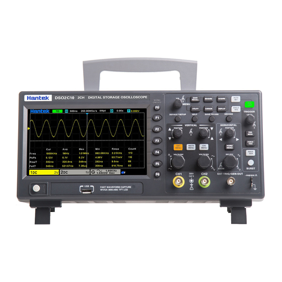
DSO2000 series digital storage oscilloscope introduction DSOXXXX Series oscilloscopes cover the bandwidths from 100MHz to 150MHz, and provide the real-time up to 1GSa/s. In addition, they have 7 inchs color TFT LCD as well as WINDOWS-style interfaces and menus for easy operation. -
Page 8: Introduction
1. Introduction 1.1. General Inspection Please check the instrument as following steps after receiving an oscilloscope: Check the shipping container for damage: Keep the damaged shipping container or cushioning material until the contents of the shipment have been checked for completeness and the instrument has been checked mechanically and electrically. Check the accessories: Accessories supplied with the instrument are listed in "Accessories"... - Page 9 digital oscilloscope so that you can get familiar with this series of digital oscilloscope well within the shortest time. 1. Power button 2. Bracket 3. USB interface 4. Menu selection key 5. Vertical control system 6. CH1、CH2 Input Channel for signal 7.
-
Page 10: The User Interface
This section will make you understand the front operation panel of this series of digital oscilloscope at first before use. 1. Hantek logo. 2. Trigger Status. AUTO: The oscilloscope works in auto mode and is acquiring waveform in the absence of triggers. -
Page 11: Functional Check
12. Trigger level. 1.5. Functional Check Follow the steps below to perform a quick functional check to your oscilloscope. 1.5.1. Connect the oscilloscope Set the switch on the probe to X 10 and connect the probe to Channel 1 on the oscilloscope. First, align the slot in the probe connector with the protuberance on the CH1 BNC and push to connect;... -
Page 12: Manual Probe Compensation
1.6.2. Manual Probe Compensation Upon the first connection of a probe and an input channel, you should manually perform this adjustment to match the probe to the input channel. Uncompensated or miscompensated probes may lead to errors or faults in measurement. To adjust the probe compensation, follow the steps below. 1. -
Page 13: Function Introduction
Make sure that the Attenuation switch on the probe matches the Probe option in the oscilloscope. Switch settings are 1X and 10X. When the Attenuation switch is set to 1X, the probe limits the bandwidth of the oscilloscope to 6MHz. To use the full bandwidth of the oscilloscope, be sure to set the switch to 10X. - Page 14 ◼ [UTILITY]: "Auxiliary function" menu, to view system information, perform system upgrades, self-calibration and other auxiliary functions. ◼ [CURSOR]: "Cursor" measurement menu, when using cursor measurement, you can use the [V0] knob to adjust the cursor position. ◼ [DISPLAY]: "Display Parameters" menu, to set the oscilloscope display parameters such as waveform brightness, grid type, and persist.
-
Page 15: Connector
◼ [TRIG MENU]: "Trigger parameter" control menu, to set trigger parameters such as trigger type and trigger mode. ◼ [FORCE TRIG]: No matter whether the oscilloscope detects the trigger or not, this button can be used to stabilize the current waveform, which is mainly used for "sampling" and "single time" in the trigger mode. -
Page 16: Oscilloscope Setup
Hide/Show softkey. Push it to hide the menu options on the right side of the screen and give a full screen display of waveform. Push it again to show the menu options. F1-F5: These five softkeys are all multi-functional. They are in charge of selecting corresponding menu options on the screen in different menu modes. -
Page 17: Vertical System
Horizontal offset knob SEC/DIV knob 1. Horizontal Offset Knob: Used to control the trigger position against the screen center. Push this button to reset the trigger point back to the screen center. 2.SEC/DIV Knob: Used to change the horizontal time scale so as to magnify or compress the waveform horizontally. -
Page 18: Math Operation
Selects the resolution of the VOLTS/DIV knob. Coarse Coarse defines a 1-2-5 sequence. Fine changes the resolution to small steps between the Fine Coarse settings. Selects a value according to the probe attenuation factor so as to ensure correct vertical Probe 100X readouts. - Page 19 4. Press the Scale softkey, and turn the Multifunctional Knob to select the vertical scale. 5. Press the Offset softkey, and turn the Multifunctional Knob to set offset. Multiplication and Division Math operators perform arithmetic operations multiplication or division operation on any two analog input channels.
- Page 20 ➢ Analyze vibration To display FFT waveform: 1. Press the [Math] button on the front panel to open the MATH function menu. 2. Press the Operation softkey and then turn the Multifunctional Knob to select FFT. The resulting math waveform is displayed on the screen and labeled with “M”. 3.
-
Page 21: Trigger System
Using Cursors to measure FFT waveform To make cursor measurements, press the Cursors button to turn the cursors, and then press the Mode softkey to select Manual or Track, Use the AX and BX cursors to measure frequency values and the difference between two frequency values (BX-AX). -
Page 22: Edge Trigger
Acquisition Interval Acquisition Interval Trigger Level Indicates Trigger Points Holdoff Holdoff 2.7.1. Edge Trigger Edge trigger distinguishes the trigger points by seeking the specified edge (rising, falling, rising & falling) and trigger level. 1. Press the [Trig Menu] button on the front panel to enter the Trigger system function menu. 2. -
Page 23: Pulse Trigger
8. Press the Holdoff softkey and turn V0 to set the time that the oscilloscope waits before a trigger to the next trigger, so that complex waveforms are displayed stably. Note: Press the [Auto Set] button will set the trigger type to Edge and slope to rising. 2.7.2. -
Page 24: Video Trigger
= (equal to time value): trigger when the positive or negative slope time of the input signal is equal to the specified time value. For example, for a positive pulse, if you set t (pulse real width) = 200ns, the waveform will trigger. 7. -
Page 25: Slope Trigger
5. Press the Standard softkey to select the desired video standard. The series of scope support the following video standards: PAL and NTSC. 6. Press the Sync softkey, then turn the Multifunctional Knob to select field or line. 7. Press the Line Num softkey and turn V0 to set the line number in the field to be triggered. 8. -
Page 26: Overtime Trigger
than the specified time value. > (greater than a time value): trigger when the positive or negative slope time of the input signal is greater than the specified time value. !=(not equal to a time value): trigger when the positive or negative slope time of the input signal is not equal to the specified time value.. -
Page 27: Window Trigger
Auto: When the oscilloscope meets the trigger condition, it completes a trigger acquisition once; when the trigger condition is not met, it can run the acquisition waveform freely. Normal: When the oscilloscope meets the trigger condition, the input waveform is displayed; when the trigger condition is not met, the original waveform is displayed. -
Page 28: Pattern Trigger
6. Press the Holdoff softkey and turn V0 to set the time that the oscilloscope waits before a trigger to the next trigger, so that complex waveforms are displayed stably. 2.7.7. Pattern Trigger Identify a trigger condition by looking for a specified pattern. This pattern is a logical "AND" or “Or” combination of channels. -
Page 29: Interval Trigger
: Set the pattern to the rising edge of the channel selected. : Set the pattern to the falling edge of the channel selected. : Set the pattern to the rising or falling edge of the channel selected. 5. Press the Level softkey to set the trigger level. For the analog channels, the trigger level of each channel needs to be set independently. -
Page 30: Under Amp Trigger
> (greater than a time value): trigger when the positive or negative pulse time of the input signal is greater than the specified time value. != (not equal to a time value): trigger when the positive or negative pulse time of the input signal is not equal to the specified limit of time. -
Page 31: Uart Trigger
7. Press the Level softkey to select Upper(V1) or Lower(V2) trigger level, and turn the Multifunctional Knob to set the position, make the Under Amp pulse to be captured between the two levels. 8. Press the Mode softkey, turn V0 to select the trigger mode (auto, normal), and press V0 to confirm. Auto: When the oscilloscope meets the trigger condition, it completes a trigger acquisition once;... -
Page 32: Lin Trigger
➢ Parity error: The oscilloscope triggers when the parity check is error when there is parity check. ➢ Com error: The oscilloscope triggers when the received data is error. Note: Use V0 to set the data. When the arrow shows vertical on the top left of Data menu, turn V0 to set the value of the current data bit;... -
Page 33: Can Trigger
➢ Identifier (Frame ID) - The oscilloscope triggers when a frame with an ID equal to the selected value is detected. Use the Multifunctional Knob to select the value for the Frame ID. ➢ ID and Data (Frame ID and Data) - The oscilloscope triggers when a frame with an ID and data equal to the selected values is detected. -
Page 34: Spi Trigger
ID and data. a. Press Data software, use V0 to set the data, refer to 2.7.10; b. Data Mask: When set to "ON", the data is ignored when it is triggered; the setting is "OFF", and the data on the data line must be consistent with the data of the index so that it can trigger; c. -
Page 35: Iic Trigger
Data Mask: it is hexadecimal, 0-Mask, f-No Mask, 1~e mask some data. 5. Trigger Condition: Press Overtime softkey to set the timeout, the range is from 8 ns to 10 s. Timeout: the clock (SCL) signal need to maintain a certain idle time before the oscilloscope searches for a trigger. -
Page 36: Protocol Decode
➢ Start: trigger when SDA data transitions from high level to low level while SCL is high level. ➢ Stop: trigger when SDA data transitions from low level to high level while SCL is high level. ➢ No Ack: trigger when the SDA data is high level during any acknowledgement of SCL clock position. ➢... -
Page 37: Lin Decode
UART decode settings: Source: CH1; Baud: 19200; Idle: High; Parity: No; Data Bit: 8; When: “Start”. The trigger result is shown below: UART Decode interpretation: 1. The decode data is displayed in hexadecimal; 2. The decoded data is at the bottom of the waveform interface by default, and displayed in purple; 3. -
Page 38: Can Decode
LIN Decode interpretation: 1. The decode data is displayed in hexadecimal; 2. The decoded data is at the bottom of the waveform interface by default. The color of "Frame ID" and "Checksum" is purple, and the color of "Data" is blue; 3. - Page 39 The trigger result is shown below: CAN Decode interpretation: 1. The decode data is displayed in hexadecimal; 2. The decoded data is at the bottom of the waveform interface. The color of “frame ID” is displayed purple, the “Data” is blue, the “CRC” is purple; 3.
-
Page 40: Spi Decode
2.8.4. SPI Decode SPI decode settings:SCL: CH2; SDA: CH1; Slope: Rising; Data Width: 8; Overtime: 8.37us. The trigger result is shown below: SPI Decode interpretation: 1. The decode data is displayed in hexadecimal; 2. The decoded data is at the bottom of the waveform interface. The color of “Data” is displayed purple; 3. -
Page 41: Save/Recall
IIC Decode interpretation: 1. The decode data is displayed in hexadecimal; 2. The decoded data is at the bottom of the waveform interface. The color of “Address” and “Data” are displayed purple; "W" indicates the write operation, "R" indicates the read operation, "D" indicates the decoded data, "~A"... -
Page 42: Internal Save And Recall
default save type is setups. The saved setups, waveform and Ref can be recalled from an USB Host interface on the front panel to connect an USB device for external storage. 1. Setup It’s the default storage type of the scope. It saves the settings of the oscilloscope in internal or external memory in “.set”... -
Page 43: External Save And Recall
pop-out the message “Save successfully”. 2.9.1.2. Recall the oscilloscope setup file of internal memory If want to recall the setup after having finished the steps above, please do the following steps: Press the Recall softkey, and then turn the Multifunctional Knob to select the location that you want to recall, press the Recall softkey to recall the setup, and it will pop-out the message “Recall Successfully”. -
Page 44: File Manager
2. Insert the USB storage device into the front panel USB Host interface, if thedevice is recognized successful, the pop-uptip “Storage device is connected”. 3. Press the Save softkey to enter save menu. 4. Press the Type softkey to select Save Type to Picture. 5. -
Page 45: Measure System
6. To delete the name in the name input area, press Switch Focus To softkey to switch to Name Input Area. Press the Delete softkey continuously to delete the character on the left of the cursor one by one. Turn V0 to move the cursor position. 7. -
Page 46: Cursor Measurement
2.10.2. Cursor measurement Cursor: This method allows you to take measurements by moving the cursors. Cursors always appear in pairs and the displayed readouts are just their measured values. There are two kinds of cursors: Amplitude Cursor and Time Cursor. The amplitude cursor appears as a horizontal dotted line, measuring the vertical parameters. -
Page 47: Automatic Measurement
2.10.3. Automatic Measurement Automatic Measurement: The oscilloscope performs all the calculations automatically in this mode. As this measurement uses the waveform record points, it is more precise than the graticule and cursor measurements. Automatic measurements show the measurement results by readouts which are periodically updated with the new data acquired by the oscilloscope. - Page 48 values of at most 4 measurement items that are turned on last. 1. Press the [Meas] button on the front panel to enter the Measure function menu. 2. Press the Statistics softkey to select ON. To Make All Measurement All measurement could measure all parameters of the current measurement source and display the results on the screen.
-
Page 49: Dvm
Measure the time between the first rising edge and the next falling edge at the waveform 50% + Width level. Measure the time between the first falling edge and the next rising edge at the waveform 50% - Width level. Measure the first cycle waveform. -
Page 50: Acquire
measurement is always performed when the oscilloscope is running or stopped. Press [MEASURE] on the front panel to enter the measurement interface, and press F3 to select the DVM to enter DVM setting interface. Press CH1 Enable, CH2 Enable to enable any channel or all channels of DVM. Press CH1 Type, CH2 Type to select the data type displayed by DVM. -
Page 51: Xy Mode
When you acquire an analog signal, the oscilloscope will convert it into a digital one. The real-time acquisition has four modes: Normal, Peak Detect, Average and High Resolution. The acquisition rate is affected by the setting of time base. Normal: In this acquisition mode, the oscilloscope samples the signal in evenly spaced intervals to establish the waveform. -
Page 52: Roll Mode
format plots the voltage on CH1 against the voltage on CH2, where CH1 is the horizontal axis and CH2 is the vertical axis. The oscilloscope uses the untriggered Normal acquisition mode and displays data as dots. The oscilloscope can acquire waveform in YT mode at any sampling rate. You may view the same waveform in XY mode. -
Page 53: Update Firmware
Calibrate Press this option and the Self Calibration dialog pops up. Refer to tips to perform the self calibration or cancel. Front Panel Self Test Test the function of all keys and knobs on the front panel. Legal Information Display source code license. 2.14.1. -
Page 54: Fast Action Buttons
SavaTo 1-10 locations for internal flash memory. Save Save the rule setups. Recall Recall the waved rule setups. Message On/Off Turn on or off the display of the number of failed passes. Run/Stop Run or stop the pass/fail test. Output Stop On/Off Enter STOP state if output exist or continue to run if output exists. -
Page 55: Default Setup
SEC/DIV Adjusted Trigger Coupling Adjusted to DC, Noise Reject or HF Reject Trigger Holdoff Minimum Trigger Level Set to 50% Trigger Mode Auto Trigger Source Adjusted; Auto Scale can not be used for the EXT TRIG signal Trigger Slope Adjusted Trigger Type Edge Trigger Video Sync... -
Page 56: Dual-Window Mode
Persist Display Mode Window Mode Single-window Trigger Knob Level Horizontal Position 0.00s SEC/DIV 200μs Math Status Measure Status Type Edge Source Trigger (Edge) Slope Rising Mode Auto Level 0.00v Bandwidth Limit Unlimited VOLTS/DIV Coarse Vertical System, Probe Attenuation All Channels Invert Position 0.00div (0.00V) -
Page 57: Waveform Generator
Dual-window Mode 3. Waveform Generator The series oscilloscope is equipped with waveform generator function, with one channel of arbitrary waveform output. User can edit the arbitrary waveform or choose the regular waveform such as Sine, Ramp, Square, Exponent, Noise, DC and Arb waveform. 3.1. -
Page 58: Waveform Modulation Setting
type. 3. Press the Frequency softkey to set frequency, press this key repeatedly to set the Period or Frequency/Period fine, and turn the Multifunctional Knob to set the value. 4. Press the Amplitude softkey to set amplitude, press this key repeatedly to set the High Level (Offset automatically switches to low level) or Amplitude /High Level fine, and turn the Multifunctional Knob to set the value. -
Page 59: Burst Setting
: Vertical arrow, turn the Multifunctional Knob to set a value. 3.3. Burst setting Press the front panel Burst button to enter the burst menu. Press the Count soft key to set the number of pulses. The range is 1~1024. The data source is specified as manual. -
Page 60: Output Arbitrary Waveform
: Download waveform data to the device. : Smooth Drawing Mode. You can draw any waveform shape using the left-mouse. : Line Drawing Mode. You can click on the waveform to draw a straight line from the previous point. : Zoom tools. To zoom the time axis in or out, click the + or - zoom button and then click on the waveform area. -
Page 61: Remote Control
The waveform will output from GEN OUT BNC port. Also, you can recall ARB format file in USB disk to output a waveform. Press the Wave Gen button on the front panel to enter Wave Gen function menu. Press the Wave softkey, turn the Multifunctional Knob to select Arb1~Arb4 and then press the knob to confirm. - Page 62 After installation, you can see the running IO software in the lower right corner of the screen. Double-click to open the IO software, you can see the connected device information displayed under My Instrument-USB. 62 / 72...
-
Page 63: Troubleshooting
2) Check the power on/off button to ensure it has been pushed; 3) Then restart the oscilloscope. Contact your local HANTEK distributor or directly keep touch with HANTEK Technical Support department if the oscilloscope still can not be turned on normally. -
Page 64: Services And Support
However, it is not suitable for all kinds of input signals. 6. Services and Support Thank you for choosing HANTEK. Please contact us through the following ways should you have any inquiry regarding our products. We shall do our best to help you. -
Page 65: General Care And Cleaning
Appendix A: Technical Specifications All technical specifications are applicable to DSO2000 series digital storage oscilloscopes, see the last part of this chapter for details. To verify whether the oscilloscope meets the technical specifications, the oscilloscope must first meet the following conditions: ➢... - Page 66 ➢ The oscilloscope must be within the factory calibration interval. All specifications are guaranteed unless noted ‘typical’. Oscilloscope Specifications Horizontal SEC/DIV Range 2ns/div to 100s/div, in a 1, 2, 5 sequence Single, sampling mode ± (1 sample interval +100ppm × reading + 0.6ns) Delta Time Measurement Accuracy >16 times above average (Full Bandwidth)
- Page 67 Mode Auto, Normal, single CH1~CH2 ±5 divisions from center of screen Level 3.3V [CMOS] Holdoff Range 20ns ~ 10s Trigger Level Accuracy CH1~CH2 0.2div × volts/div within ±4 divisions from center of screen ±0.2div Trigger sensitivity Edge Trigger Slope Rising, Falling, Rising&Falling Source CH1~CH2, Line, External Pulse Trigger...
- Page 68 Time Range 8ns ~ 10s Under Amp Trigger Polarity Positive, Negative Condition <, >, !=, = Source CH1~CH2 Time Range 8ns ~ 10s UART Trigger Condition Start, Stop, Data, Parity Error, COM Error Source CH1~CH2 Data format Condition <, >, !=, = Data Length 1 byte Data Bits Width...
- Page 69 Source (SDA/SCL) CH1~CH2 Data format Data Index Condition Start Bit, Stop Bit, No Ack, Address, Restart, Addresss and Data Inputs Number of channels 2 analog channels Input Coupling DC, AC or GND Input Impedance, DC coupled 20pF±3pF, 1MΩ±2% Probe Attenuation 1X, 10X Supported Probe Attenuation Factors 1X, 10X, 100X, 1000X...
- Page 70 Sine Frequency Range 0.1Hz~25MHz Frequency Range 0.1Hz~10MHz Square Duty 1%~99% Frequency Range 0.1Hz~1MHz Ramp Symmetry 0%~100% Exponential Frequency Range 0.1Hz~5MHz >25MHz Noise Bandwidth Offset 1.75V(50Ω), 3.5V(High resistance) Frequency Range 1uHz~25MHz Arbitrary wave Wave length 4096 Support PC download and external memory recall Output impedance 50 Ω+1%, high impedance 5mV~3.5Vpp(50Ω)
-
Page 71: Appendix B: Accessories
318 x 110 x 150mm (L x W x H) Weight 1900g Appendix B: Accessories All the following accessories are available by contacting your local HANTEK distributor. Standard Accessories ⚫ A Passive Probe (1.5m, 10:1) ⚫ A Test Lead with two clips ⚫... -
Page 72: Appendix C Harmful And Poisonous Substances Or Elements
Appendix C Harmful and Poisonous Substances or Elements Harmful and poisonous substances or elements Component Cr (Vi) PBDE Shell and Chassis Display Module Circuit Board Power Supply Electric Wire and Cable Assembly Connector Fastener and Installed Hardware Other Accessories (including probes) Others ‘X’...
Need help?
Do you have a question about the DSO2000 Series and is the answer not in the manual?
Questions and answers
Is the screen on a DSO2D15 Scope a touchscreen and if it is, how do I make it work?
The screen on the Hantek DSO2D15 scope is not a touchscreen. It operates using physical buttons, function keys, and control knobs located around the screen.
This answer is automatically generated
is screen a touchscreen and if it is, how do I make it work?
The context does not mention whether the Hantek DSO2000 Series screen is a touchscreen. However, it describes various physical buttons, knobs, and function keys for operating the oscilloscope, suggesting it is controlled through these physical inputs rather than a touchscreen.
This answer is automatically generated
Добрый день ! Я могу проверить напряжение сети в розетке?