Table of Contents
Advertisement
Advertisement
Table of Contents

Subscribe to Our Youtube Channel
Related Manuals for Hantek DSO2000 Series


Summary of Contents for Hantek DSO2000 Series
- Page 1 DSO2000 Series Digital Storage Oscilloscope User Manual (V1.0)...
-
Page 2: Copyright Declaration
Hantek reserves all rights to modify this document without prior notice. Please contact Hantek for the latest version of this document before placing an order. Hantek has made every effort to ensure the accuracy of this document but does not guarantee the absence of errors. Moreover, Hantek assumes no responsibility in obtaining permission and authorization of any third party patent, copyright or product involved in relation to the use of this document. -
Page 3: General Safety Summary
General Safety Summary Read the following safety precautions to avoid injury and prevent damage to this product or any products connected to it. To evade potential hazards, use this product only as specified. Only qualified personnel should perform maintenance. Avoid fire or personal injury. Use suitable power cord. -
Page 4: Safety Terms And Symbols
Safety Terms and Symbols Terms on the product. The following terms may appear on the product: Danger It represents that harms may be caused to you at once if you perform the operation. Warning It represents that latent harms may be caused to you if you perform the operation. Notice It represents the damage possibly caused to the product or other properties if you perform the operation. -
Page 5: Table Of Contents
Contents Copyright Declaration ....................................2 General Safety Summary ..................................3 Safety Terms and Symbols ..................................4 Product Scrapping ....................................4 DSO2000 series digital storage oscilloscope introduction ......................... 7 Introduction ....................................8 1.1. General Inspection ..................................8 1.2. Prepare Instrument for Use ................................8 1.3. - Page 6 2.8.3. CAN Decode ....................................38 2.8.4. SPI Decode ....................................39 2.8.5. IIC Decode ..................................... 39 2.9. Save/Recall ....................................40 2.9.1. Internal Save and Recall ................................41 2.9.2. External save and recall ................................42 2.9.3. Save picture ....................................42 2.9.4. File Manager ....................................43 2.10.
-
Page 7: Dso2000 Series Digital Storage Oscilloscope Introduction
DSO2000 series digital storage oscilloscope introduction DSOXXXX Series oscilloscopes cover the bandwidths from 70MHz to 150MHz, and provide the real-time up to 1GSa/s. In addition, they have 7 inch color TFT LCD as well as WINDOWS-style interfaces and menus for easy operation. -
Page 8: Introduction
1. Introduction 1.1. General Inspection Please check the instrument as following steps after receiving an oscilloscope: Check the shipping container for damage: Keep the damaged shipping container or cushioning material until the contents of the shipment have been checked for completeness and the instrument has been checked mechanically and electrically. Check the accessories: Accessories supplied with the instrument are listed in "Accessories"... -
Page 9: The User Interface
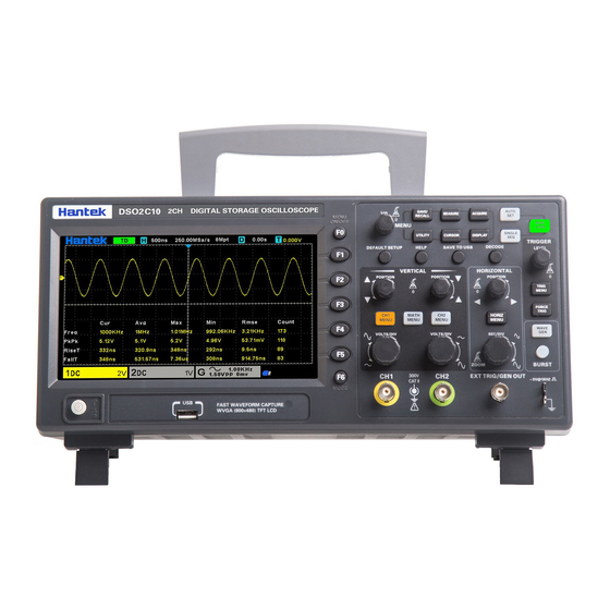
1. Power button 2. Bracket 3. USB interface 4. Menu selection key 5. Vertical control system 6. CH1、CH2 Input Channel for signal 7. Horizontal control system 8. Signal source output/external trigger input channel 9. Probe compensation function zone 10. Signal source 11. -
Page 10: Functional Check
1. Hantek logo. 2. Trigger Status. AUTO: The oscilloscope works in auto mode and is acquiring waveform in the absence of triggers. READY: All pre-triggered data have been acquired and the oscilloscope is ready to accept a trigger. ROLL: The oscilloscope is acquiring and displaying waveform data continuously in roll mode. -
Page 11: Connect The Oscilloscope
1.5.1. Connect the oscilloscope Set the switch on the probe to X 10 and connect the probe to Channel 1 on the oscilloscope. First, align the slot in the probe connector with the protuberance on the CH1 BNC and push to connect; then, turn to right to lock the probe in place;... -
Page 12: Probe Attenuation Setting
Upon the first connection of a probe and an input channel, you should manually perform this adjustment to match the probe to the input channel. Uncompensated or miscompensated probes may lead to errors or faults in measurement. To adjust the probe compensation, follow the steps below. 1. -
Page 13: Function Introduction
2. Function Introduction This chapter provides some general information that you need to learn before using an oscilloscope. It contains: 2.1. Menu and Control Keys As shown in the figure below: All the keys are described as follows: Menu keys ◼... - Page 14 ◼ [SINGLE SEQ]: Acquire a single trigger, finish acquisition and then stop. Shortcut keys ◼ [DEFAULT SETUP]: Recall the default factory setup. ◼ [HELP]: View the "Help" message and press this key again to exit the help. ◼ [SAVE TO USB]: Press to quickly save the screenshot to the USB disk. Insert the USB disk before use. ◼...
-
Page 15: Connector
2.2. Connector ◼ CH1, CH2: for an input connector of a measured signal. ◼ EXT TRIG/GEN OUT: Function multiplexing connector, can be used for signal source waveform output and external trigger signal input. External trigger can trigger on the third channel while collecting data. ◼... -
Page 16: Horizontal Controls
automatically recall the setup once being turned on. (Note: If you modify the setup, please wait for more than 10 seconds before turning off the oscilloscope to ensure the proper storage of new settings.) You can save 10 settings permanently in the oscilloscope and reset them as necessary. Recalling a Setup: The oscilloscope can recall any of your saved setups or the default factory setup. -
Page 17: Math Operation
move the waveform in both windows at the same time in a same direction. Push this knob to return waveform to the vertical center position on the screen. Two channels correspond to two knobs. 2. VOLTS/DIV Knob: Control the oscilloscope to magnify or attenuate the source signal of the channel waveform. - Page 18 Operation Unit Addition (+) or subtraction (-) multiplication (*) division (/) None dB, VRms Addition or Subtraction Math operators perform arithmetic operations - add or subtract operation - on any two analog input channels. When you select addition or subtraction, the Source A and Source B values are added or subtracted point by point, and the result is displayed.
- Page 19 3. Press the Operator softkey and turn the universal to select * or / to make multiplication or division operation. The resulting math waveform is displayed on the screen and labeled with “M”. 4. Press the Scale softkey, and turn the Multifunctional Knob to select the vertical scale. 5.
- Page 20 Hamming Transient or short pulse A litter bit better frequency resolution than Hanning. Single frequency signal, Blackman search for higher order The best amplitude resolution; the poorest frequency resolution harmonics. Narrow band signal with Bartlett Better frequency resolution. stronger Flattop Periodic Waveform Better amplitude, poorer frequency accuracy than Hanning 9.
-
Page 21: Trigger System
2.7. Trigger System The trigger determines when the oscilloscope begins to acquire data and display a waveform. Once a trigger is properly set up, the oscilloscope can convert unstable displays or blank screens to meaningful waveform. Here introduce some basic concepts about trigger. Trigger Source: The trigger can be generated with multiple sources. -
Page 22: Edge Trigger
Acquisition Interval Acquisition Interval Trigger Level Indicates Trigger Points Holdoff Holdoff 2.7.1. Edge Trigger Edge trigger distinguishes the trigger points by seeking the specified edge (rising, falling, rising & falling) and trigger level. 1. Press the [Trig Menu] button on the front panel to enter the Trigger system function menu. 2. -
Page 23: Pulse Trigger
Note: Press the [Auto Set] button will set the trigger type to Edge and slope to rising. 2.7.2. Pulse Trigger Pulse trigger sets the oscilloscope to trigger on a positive or negative pulse of a specified width. You can set the trigger source, polarity (positive pulse width, negative pulse width), limit conditions, and pulse width in this menu. -
Page 24: Video Trigger
the specified time value. For example, for a positive pulse, if you set t (pulse real width) = 200ns, the waveform will trigger. 7. Press of 50% softkey to set the trigger level to the vertical midpoint between the peaks of the trigger signal. -
Page 25: Slope Trigger
Auto: When the oscilloscope meets the trigger condition, it completes a trigger acquisition once; when the trigger condition is not met, it can run the acquisition waveform freely. Normal: When the oscilloscope meets the trigger condition, the input waveform is displayed; when the trigger condition is not met, the original waveform is displayed. -
Page 26: Overtime Trigger
8. Press the Mode softkey, turn V0 to select the trigger mode (auto, normal), and press V0 to confirm. Auto: When the oscilloscope meets the trigger condition, it completes a trigger acquisition once; when the trigger condition is not met, it can run the acquisition waveform freely. Normal: When the oscilloscope meets the trigger condition, the input waveform is displayed;... -
Page 27: Pattern Trigger
⚫ If the lower and the upper trigger levels are both within the waveform amplitude range, the oscilloscope will trigger on both rising and falling edge. ⚫ If the upper trigger level is within the waveform amplitude range while the lower trigger level is out of the waveform amplitude range, the oscilloscope will trigger on rising edge only. - Page 28 To set interval trigger: 1. Press the [Trig Menu] button on the front panel to enter the Trigger system function menu. 2. Press the Type softkey, then use the Multifunctional Knob to select Pattern and push down the knob to confirm. 3.
-
Page 29: Interval Trigger
Normal: When the oscilloscope meets the trigger condition, the input waveform is displayed; when the trigger condition is not met, the original waveform is displayed. 7. Press the Holdoff softkey and turn V0 to set the time that the oscilloscope waits before a trigger to the next trigger, so that complex waveforms are displayed stably. -
Page 30: Under Amp Trigger
2.7.9. Under Amp Trigger The Under Amp trigger looks for pulses that cross one threshold but not another as shown in the picture below. ⚫ A positive under Amp pulse across through a lower threshold but not an upper threshold. ⚫... -
Page 31: Lin Trigger
3. Press the Source softkey, turn the Multifunctional Knob to select CH1~CH2 as the trigger source. 4. Set the following parameters: ➢ Idle Level: Set the idle level High or Low to match your device under test. ➢ Baud: Press the Baud Rate softkey, then press the Multifunctional Knob and select a baud rate to match the signal in your device under test. -
Page 32: Can Trigger
LIN triggering can trigger on the rising edge at the Sync Break exit of the LIN single-wire bus signal (that marks the beginning of the message frame), the Frame ID, or the Frame ID and Data. Set LIN trigger: 1. Press the [Trig Menu] button on the front panel to enter the Trigger system function menu. 2. -
Page 33: Spi Trigger
2. Press the Type softkey, then turn the Multifunctional Knob to select CAN and push down the knob to confirm. 3. Press the Source softkey, turn the Multifunctional Knob to select CH1~CH2 as the trigger source. 4. Press the Buad Tate softkey, and turn the Multifunctional Knob to set the Baud Rate. 5. -
Page 34: Iic Trigger
1. Press the [Trig Menu] button on the front panel to enter the Trigger system function menu. 2. Press the Type softkey, then turn the Multifunctional Knob to select SPI and push down the knob to confirm. 3. Source: Press SCL and SDA softkey to specify the data sources of SCL and SDA respectively. They can be set to CH1-CH2. - Page 35 2. Press the Type softkey, then turn the Multifunctional Knob to select IIC and push down the knob to confirm. 3. Source Selection: Press SCL and SDA softkey, turn the Multifunctional Knob to to specify the data sources of SCL and SDA respectively. They can be set to CH1-CH2. 4.
-
Page 36: Protocol Decode
7. Press the Holdoff softkey and turn V0 to set the time that the oscilloscope waits before a trigger to the next trigger, so that complex waveforms are displayed stably. 2.8. Protocol Decode For the menu settings under protocol decoding, please refer to the five protocol trigger settings in Trigger System. -
Page 37: Lin Decode
2.8.2. LIN Decode LIN decode settings: Source: CH1; Baud: 19200; Idle: High; When: Identifier; Identifier: 0X15; And set the trigger level. The trigger result is shown below: LIN Decode interpretation: 1. The decode data is displayed in hexadecimal; 2. The decoded data is at the bottom of the waveform interface by default. The color of "Frame ID" and "Checksum"... -
Page 38: Can Decode
2.8.3. CAN Decode CAN decode settings: Source: CH1; Baund Rate: 1000000; Idle Level: Low; When: Start Bit. The trigger result is shown below: CAN Decode interpretation: 1. The decode data is displayed in hexadecimal; 2. The decoded data is at the bottom of the waveform interface. The color of “frame ID” is displayed purple, the “Data”... -
Page 39: Spi Decode
2.8.4. SPI Decode SPI decode settings:SCL: CH2; SDA: CH1; Slope: Rising; Data Width: 8; Overtime: 8.37us. The trigger result is shown below: SPI Decode interpretation: 1. The decode data is displayed in hexadecimal; 2. The decoded data is at the bottom of the waveform interface. The color of “Data” is displayed purple; 3. -
Page 40: Save/Recall
IIC Decode interpretation: 1. The decode data is displayed in hexadecimal; 2. The decoded data is at the bottom of the waveform interface. The color of “Address” and “Data” are displayed purple; "W" indicates the write operation, "R" indicates the read operation, "D" indicates the decoded data, "~A"... -
Page 41: Internal Save And Recall
It’s the default storage type of the scope. It saves the settings of the oscilloscope in internal or external memory in “.set” format. Up to 9 setting files (No.1~No.9) can be stored in the internal memory. The stored settings can be recalled. 2. -
Page 42: External Save And Recall
Note: if need to delete a setup file in the memory, please save a new setup to the same location to overwrite it. 2.9.2. External save and recall Before using external storage and recall, make sure that the USB storage device is connected correctly. External storage supports all the types of files in save, but in recall, CSV is not supported. -
Page 43: File Manager
ON: The color of the saved picture is the opposite color of the screen. 6. Press the Save softkey to save the picture to the external USB storage device. Screenshot Press SAVE TO USB on the front panel to automatically take a screenshot to save the picture to an external storage device. -
Page 44: Measure System
2. Press the Type softkey, and then turn the Multifunctional Knob to select one type. 3. Use the SaveTo softkey to external location. Press Save softkey and into File Manager interface. 4. Turn the Multifunctional Knob V0 to select the file or folder to be deleted, and then press the Delete softkey. -
Page 45: Automatic Measurement
measured before the cursors are used. 2. Tracking mode: A horizontal cursor is intersected with a vertical cursor to form a cross cursor. The cross cursor is automatically located on the waveform, and the horizontal position of the cross cursor on the waveform is regulated by selecting “Cur A”... - Page 46 Push the Meas button to perform auto measurements. There are 32 types of measurements and up to 4 can be displayed at a time. Perform the steps below and select voltage or time parameters to make automatic measurements. 1. Press the [Meas] button on the front panel to enter the Measure function menu. 2.
- Page 47 Type Comments Frequency The reciprocal of the period. Period The time between two consecutive threshold points of the same polarity edge. Average The arithmetic mean of the entire waveform or selected area. Pk-Pk The voltage value from the peak to the lowest point of the waveform. That is a valid value.
- Page 48 Measure the first cycle waveform. Negative Duty Cycle is the ratio between positive pulse - Duty width and period. Vbase Measure the highest voltage over the entire waveform. Vtop Measure the lowest voltage over the entire waveform. Vmid Measure the voltage of the 50% level from base to top. Vamp Voltage between Vtop and Vbase of a waveform.
-
Page 49: Dvm
Gate measurement In the second page of measurement main menu, select Gate softkey to enter gate menu. Only when the type of measurement is opened, the gate measurement can be opened. After opening the gate measurement, the measurement results only measure the waveform between the cursor A and the cursor B. - Page 50 When [Single] is pressed, the display is cleared, the trigger mode is temporarily set to Normal (to keep the oscilloscope from auto-triggering immediately), the trigger circuitry is armed, the Single key is illuminated, and the oscilloscope waits until a user defined trigger condition occurs before it displays a waveform.
-
Page 51: Xy Mode
Roll determines the Y coordinate (vertical). For detailed information, refer to descriptions on XY format in the following text. Averages 4, 8, 16, 32, 64, 128 Select the number of averages by pressing F3 or F4. Memory Depth 4K, 8K, 16K, 4M, 8M The maximum single-channel display is 8M. -
Page 52: Utility System
Persist Infinite Sets the time length to display each displayed sample point. 1s, 5s, 10s,30s 2.14. Utility System Push the UTILITY button to display the Utility Menu as follows. Options Comments Language Set the language Sound Set the buzzer. Update Insert a USB disk with upgrade program. -
Page 53: Self Calibration
2.14.2. Self Calibration The self calibration routine helps optimize the oscilloscope signal path for maximum measurement accuracy. You can run the routine at any time but should always run it if the ambient temperature changes by 5℃ or more. For a more accurate calibration, please power on the oscilloscope and wait for 20 minutes until it has adequately warmed up. -
Page 54: Fast Action Buttons
2.15. Fast Action Buttons Auto Set: Automatically set the oscilloscope controls to generate a usable display of the input signals. Refer to the following table for relative content. Single: Acquire a single waveform and then stop the acquisition. Run/Stop: Continuously acquire waveform or stop the acquisition. Default Setup: automatically recall the default settings. -
Page 55: Default Setup
Trigger Level Set to 50% Trigger Mode Auto Trigger Source Adjusted; Auto Scale can not be used for the EXT TRIG signal Trigger Slope Adjusted Trigger Type Edge Trigger Video Sync Adjusted Trigger Video Standard Adjusted Vertical Bandwidth Full Vertical Coupling DC (if GND was chosen before);... - Page 56 When you push the DEFAULT SETUP button, the oscilloscope will display the CH1 waveform and remove all the others. When you are at the default setup, press F5 to Undo Preset. Then the oscilloscope returns to the status before default setup. The table below gives the options, buttons and controls that change settings at default setup.
-
Page 57: Dual-Window Mode
Invert Position 0.00div (0.00V) VOLTS/DIV The following settings do not change when you push the [Default] button. ➢ Language Option ➢ Saved Settings ➢ Saved Reference waveform ➢ Display Contrast ➢ Calibration Data 2.15.3. Dual-window Mode Press the Sec/DIV knob to enter the dual-window mode, and press the button again to exit the dual-window mode. -
Page 58: Waveform Generator
3. Waveform Generator The series oscilloscope is equipped with waveform generator function, with one channel of arbitrary waveform output. User can edit the arbitrary waveform or choose the regular waveform such as Sine, Ramp, Square, Exponent, Noise, DC and Arb waveform. 3.1. -
Page 59: Waveform Modulation Setting
3.2. Waveform modulation setting Press the Modulation softkey to enter the modulation menu. There are two types of modulation, amplitude modulation and frequency modulation. Amplitude modulation (AM): Modify the amplitude of the original carrier signal according to the amplitude of the modulated signal. Frequency modulation (FM): Modify the frequency of the original carrier signal according to the frequency of the modulation signal. - Page 60 Menu: Import from CSV: Import the CSV format file to the arbitrary waveform generator window. Export as CSV: Save as CSV format file. Import from ARB: Import the ARB format file to the arbitrary waveform generator window. Export as ARB: Save as ARB format file. Note: The device can recall ARB format file in USB disk, but CSV format file can’t be recalled by the device.
-
Page 61: Output Arbitrary Waveform
the Standard waveform shapes buttons, this control sets the duty cycle of the signal. Duty cycle is defined as the time that the signal spends above zero volts divided by the total cycle time. Thus, a symmetrical square or triangular wave has a duty cycle of 50%. Reducing the duty cycle shortens the positive part of the cycle and lengthens the negative part, and increasing the duty cycle does the opposite. -
Page 62: Services And Support
However, it is not suitable for all kinds of input signals. 5. Services and Support Thank you for choosing HANTEK. Please contact us through the following ways should you have any inquiry regarding our products. We shall do our best to help you. -
Page 63: General Care And Cleaning
Appendix A: Technical Specifications All specifications herein mentioned apply to the series oscilloscopes. Before checking an oscilloscope from HANTEK to see if it complies with these specifications, make sure it meets the following conditions: ➢ The oscilloscope must have been operating continuously for twenty minutes under the specified operating temperature. - Page 64 ➢ The oscilloscope must be within the factory calibration interval. All specifications are guaranteed unless noted ‘typical’. Oscilloscope Specifications Horizontal Sample Rate Range 1GS/s(Single-channel); 500MSa/s(Dual-channel); Waveform Interpolation (sin x)/x Maximum 8M for single channel (4K, 40K, 400K, 4M, 8M optional) Record Length Maximum 4M for dual channels (4K, 40K, 400K, 4M optional) SEC/DIV Range...
- Page 65 <3.5ns ≤5ns ≤2.4ns ±3% for Normal or Average acquisition mode, 10V/div to 10mV/div DC Gain Accuracy ±4% for Normal or Average acquisition mode, 5mV/div to 2mV/div Note: Bandwidth reduced to 6MHz when using a 1X probe. Acquisition Acquisition Modes Normal, Peak Detect, Average and HR Acquisition Rate, typical Up to 2000 waveform per second per channel (Normal acquisition mode, no measurement) Acquisition Mode...
- Page 66 Source CH1~CH2 Width Range 8ns ~ 10s Resolution Video Trigger Signal Standard NTSC, PAL Source CH1~CH2 Sync ScanLine, LinrNum, OddField, EvenField and AllField Slope Trigger Slope Rising, Falling Condition <, >, !=, = Source CH1 ~ CH2 Time Range 8ns ~ 10s Resolution Overtime Trigger Source...
- Page 67 Interval Trigger Slope Rising, Falling Condition <, >, !=, = Source CH1~CH2 Time Range 8ns ~ 10s Resolution Under Amp Trigger Polarity Positive, Negative Condition <, >, !=, = Source CH1~CH2 Time Range 8ns ~ 10s Resolution UART Trigger Condition Start, Stop, Data, Parity Error, COM Error Source (RX/TX) CH1~CH2...
- Page 68 LIN Trigger Condition Interval Field, Sync Field, Id field, Sync Id Error, Identifier, Id and Data Source CH1~CH2 Data format 110/300/600/1200/2400/4800/9600/14400/19200/38400/57600/115200/230400/380400 Baud Rate (Selectable) /460400 bit/s Baud Rate (Custom) 300bit/s~334000bit/s CAN Trigger Start Bit, Remote Frame, Data Frame Id, Frame Id, DataFrame Id A, Error Frame, All Error, Condition Ack Error, Overload Fram Source...
- Page 69 Inputs Input Coupling DC, AC or GND Input Impedance, 1MΩ±2% in parallel with 20pF±3pF coupled Probe Attenuation 1X, 10X Supported Probe 1X, 10X, 100X, 1000X Attenuation Factors Overvoltage Category 300V CAT II Maximum Input Voltage 300V (10X) Measurements Voltage difference between cursors: △V Time difference between cursors: △T Cursors Reciprocal of △T in Hertz (1/ΔT)
- Page 70 120-240VAC (±10%), 45Hz to 66Hz, CATⅡ Power Consumption <30W Fuse T, 3.15A, 250V, 5x20mm Environmental Operating Temperature 0 to 50 °C (32 to 122 °F) Operation Humidity ≤90% relative humidity Storage Temperature -40 to +71 °C (-40 to 159.8 °F) Storage Humidity ≤60% relative humidity Cooling Method...
-
Page 71: Appendix B: Accessories
Frequency Stability <30ppm Output Impedance 50 Ω Appendix B: Accessories All the following accessories are available by contacting your local HANTEK distributor. Standard Accessories ⚫ Probe×2 (1.5m), 1:1, (10:1) Passive Probes ⚫ A Power line ⚫ A USB Line ⚫ A BNC to BNC(Only for the scopes with waveform generator function) ⚫... - Page 72 Connector Fastener and Installed Hardware Other Accessories (including probes) Others ‘X’ means that at least the content of this poisonous and harmful substance in a homogeneous material of this component exceeds the limit specified in the SJ/T 11363-2006 standard. ‘0’ indicates that the content of this poisonous and harmful substance in all homogeneous materials of this component is refrained under the limit stated in the SJ/T 11363-2006 standard.
Need help?
Do you have a question about the DSO2000 Series and is the answer not in the manual?
Questions and answers