
Related Manuals for Siemens LME39 Series


Summary of Contents for Siemens LME39 Series
- Page 2 Warning notes To avoid injury to persons, damage to property or the environment, the following warning notes must be observed! Do not to open, interfere with or modify the unit! • All activities (mounting, installation and service work, etc.) must be performed by quali- fied staff •...
- Page 3 The OEM is obliged to mark the unit accordingly and to include at least the list of device parameters and settings in the burner’s documentation. Siemens also recommends attaching an additional mark on the LME39… in the form of an adhesive label. As specified in EN 298, the label should be easy to read and wipe proof.
- Page 4 Since the BCI interface has no safe separation from mains voltage, the connecting ca- ble between LME39… and AZL2…, or LME39… and OCI400 / OCI410…, must con- form to certain specifications. Siemens has specified the cable for use under the burner hood (cable supplied by Hütter; refer to «Technical data»). When using cables of other manufacture, Siemens’...
- Page 5 Electrical connection of flame detectors It is important to achieve practically disturbance- and loss-free signal transmission: • Never run detector cables together with other cables – Line capacitance reduces the magnitude of the flame signal – Use a separate cable •...
- Page 6 Standards and certificates Conformity to EEC directives - Electromagnetic compatibility EMC (immunity) 2004/108/EC - Directive for gas-fired appliances 90/396/EEC ISO 9001: 2000 ISO 14001: 2004 Cert. 00739 Cert. 38233 Identification code to EN 298 LME39.100… F T C L B N A B C L B N LME39.400…...
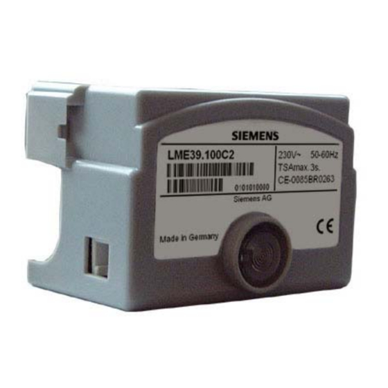
- Page 7 Type summary (other types of burner controls on request) The product nos. given below apply to the LME39… burner control without plug-in base and without flame detector. For ordering information on plug-in bases and other accesso- ries, refer to «Ordering». t1´...
- Page 8 Technical data General unit data Mains voltage AC 120 V +10% / -15% AC 230 V +10% / -15% Mains frequency 50...60 Hz ±6% Power consumption 12 VA External primary fuse (Si) Max. 10 A (slow) Mounting position Optional Input current at terminal 12 Max.
- Page 9 Technical data (cont´d) Life cycle LME… burner controls have a designed lifetime* of 250,000 burner startup cycles which, under normal operating conditions in heating mode, correspond to approx. 10 years of usage (starting from the production date given on the type field). This lifetime is based on the endurance tests specified in standard EN 298 and the table containing the relevant test documentation as published by the European Association of Component Manufacturers (Afecor) (www.afecor.org).
- Page 10 Technical data (cont´d) Flame supervision Only in connection with LME39…A2 (AC 230 V)! with AGQ3…A27 and UV detector QRA... Mains voltage AC 230 V +10% / -15% 50...60 Hz ±6% Mains frequency Perm. cable length from QRA... to Max. 20 m AGQ3…A27 (lay separate cable) Perm.
- Page 11 Functions • Preconditions for Burner control must be reset • burner startup All contacts in the line are closed, request for heat • No undervoltage • Air pressure switch «LP» or CPI must be in its no-load position, or DBR2 is connected •...
- Page 12 Functions (cont´d) Resetting the burner When lockout occurs, the burner control can immediately be reset. To do this, press the control lockout reset button for about 1 second (<3 seconds). The LME39… can only be reset when all contacts in the line are closed and when there is no undervoltage. Limitation of repetitions If no flame is established at the end of «TSA», or if the flame is lost during operation, a (c an be parameterized )
- Page 13 Operation, indication, diagnostics Lockout reset button «EK...» is the key operating element for resetting Operation the burner control and for activating / deactivating the diagnostics func- tions. The multicolor signal lamp (LED) in the lockout reset button is the key Yellow indicating element for visual diagnostics and interface diagnostics.
- Page 14 Operation, indication, diagnostics (cont´d) Diagnostics of the After lockout, the red fault signal lamp is steady on. In that condition, visual diagnostics of cause of fault the cause of fault according to the error code table can be activated by pressing the lock- out reset button for at least 3 seconds.
- Page 15 Connection diagram and control sequence of LME39.100... A´ B´ μC control SB / GP RESET R / W (LR) BV2 R / W t10* t3n* BV1 BV2 t12* TSA* t11* 7106a05e/1206 * Times can be parameterized within the min. / max. limits ** TSA = t3n + 0.7 s Connection diagram and control sequence of LME39.400...
- Page 16 Legend Start command (switching on by «R») B-B´ Interval for establishment of flame Operating position of burner reached Burner operation (generation of heat) Controlled shutdown by «R» • Burner is immediately shut down • Burner control is immediately ready for new startup Cam I actuator Prepurge time t1´...
Need help?
Do you have a question about the LME39 Series and is the answer not in the manual?
Questions and answers