Table of Contents
Advertisement
Quick Links
Advertisement
Table of Contents
Troubleshooting

Related Manuals for Lenovo ThinkSystem SR635 V3


Summary of Contents for Lenovo ThinkSystem SR635 V3
- Page 1 ThinkSystem SR635 V3 User Guide Machine Type: 7D9G, 7D9H...
- Page 2 Before using this information and the product it supports, be sure to read and understand the safety information and the safety instructions, which are available at: https://pubs.lenovo.com/safety_documentation/ In addition, be sure that you are familiar with the terms and conditions of the Lenovo warranty for your server, which can be found at: http://datacentersupport.lenovo.com/warrantylookup Second Edition (April 2023) ©...
-
Page 3: Table Of Contents
Server package contents ... Install a GPU adapter ... Identify the server and access the Lenovo XClarity Server replacement ... . . - Page 4 ....168 Set the network connection for the Lenovo XClarity Rear drive assembly replacement ..169 Controller .
- Page 5 Set front USB port for Lenovo XClarity Controller Keyboard, mouse, KVM switch or USB-device connection....282 problems ....321 Update the firmware .
- Page 6 ThinkSystem SR635 V3 User Guide...
-
Page 7: Safety
Vor der Installation dieses Produkts die Sicherheitshinweise lesen. Prima di installare questo prodotto, leggere le Informazioni sulla Sicurezza. Les sikkerhetsinformasjonen (Safety Information) før du installerer dette produktet. Antes de instalar este produto, leia as Informações sobre Segurança. © Copyright Lenovo 2023... -
Page 8: Safety Inspection Checklist
1 & IEC 60950-1, the standard for Safety of Electronic Equipment within the Field of Audio/Video, Information Technology and Communication Technology. Lenovo assumes you are qualified in the servicing of equipment and trained in recognizing hazards energy levels in products. Access to the equipment is by the use of a tool, lock and key, or other means of security, and is controlled by the authority responsible for the location. - Page 9 Click Power ➙ Power Cables to see all line cords. • Make sure that the insulation is not frayed or worn. 3. Check for any obvious non-Lenovo alterations. Use good judgment as to the safety of any non-Lenovo alterations.
- Page 10 ThinkSystem SR635 V3 User Guide viii...
-
Page 11: Chapter 1. Introduction
Chapter 1. Introduction The ThinkSystem SR635 V3 Server (Types 7D9G and 7D9H) is a 1-socket 1U rack server that features the 4th generation EPYC processor family of AMD. It is designed to be highly flexible to support many kinds of Information Technology (IT) workloads. -
Page 12: Tech Tips
The server provides a QR code on the system service label, which is on the cover of the server, that you can scan using a QR code reader and scanner with a mobile device to get quick access to the Lenovo Service Information website. -
Page 13: Security Advisories
Security advisories Lenovo is committed to developing products and services that adhere to the highest security standards in order to protect our customers and their data. When potential vulnerabilities are reported, it is the responsibility of the Lenovo Product Security Incident Response Team (PSIRT) to investigate and provide information to our customers so they may put mitigation plans in place as we work toward providing solutions. - Page 14 • PCIe x16/x16, low-profile + low-profile • PCIe x16/x16, low profile + full-height • PCIe x16, full-height PCIe slot availability is based on riser selection. See “Rear view” on page 23 “PCIe slots and adapters” on page ThinkSystem SR635 V3 User Guide...
- Page 15 • Gen 4: 440, 540 and 940 series • Gen 3: 4350, 5350 and 9350 series Note: For more information about the RAID/HBA adapters, see Lenovo ThinkSystem RAID Adapter and HBA Reference Graphics processing unit (GPU) The server supports the following GPU: • Low-profile, half-length, single-wide: –...
- Page 16 • Lenovo XClarity Controller (XCC), which provides service processor control and monitoring functions, video controller, and remote keyboard, video, mouse, and remote drive capabilities. – The server supports Lenovo XClarity Controller 2 (XCC2). For additional information about Lenovo XClarity Controller 2 (XCC2), refer to https://sysmgt.lenovofiles.com/help/topic/lxcc_frontend/lxcc_overview.html...
- Page 17 • Microsoft Windows • Red Hat Enterprise Linux • SUSE Linux Enterprise Server • Canonical Ubuntu References: • Complete list of available operating systems: https://lenovopress.lenovo.com/osig • OS deployment instructions, see “Deploy the operating system” on page 288. Chapter 1 Introduction...
-
Page 18: Mechanical Specifications
• Depth (with EIA flange and PSU handle): 787.6 mm (31 inches) Weight Up to 20.2 kg (44.56 lb) Environmental specifications Summary of the environmental specifications of the server. Depending on the model, some features might not be available, or some specifications might not apply. ThinkSystem SR635 V3 User Guide... - Page 19 Lenovo recommends that you consult with qualified experts in this field to determine whether you are in compliance with the applicable regulations.
- Page 20 Attention: Airborne particulates and reactive gases acting alone or in combination with other environmental factors such as humidity or temperature might pose a risk to the server. For information about the limits for particulates and gases, see “Particulate contamination” on page ThinkSystem SR635 V3 User Guide...
- Page 21 Environment ThinkSystem SR635 V3 complies with ASHRAE Class A2 specifications with most configurations, and depending on the hardware configuration, also complies with ASHRAE Class A3 and Class A4 specifications. System performance may be impacted when the operating temperature is outside ASHRAE A2 specification.
-
Page 22: Management Options
If Lenovo determines that the levels of particulates or gases in your environment have caused damage to the device, Lenovo may condition provision of repair or replacement of devices or parts on implementation of appropriate remedial measures to mitigate such environmental contamination. - Page 23 • Redfish API Usage and downloads https://sysmgt.lenovofiles.com/help/topic/lxcc_frontend/lxcc_overview.html Application that reports the XCC events to local OS system log. Interface • CLI application Lenovo XCC Logger Utility Usage and downloads https://sysmgt.lenovofiles.com/help/topic/lxcc-logger-frontend/lxcc-logger-overview.html Centralized interface for multi-server management. Interface • Web GUI interface •...
- Page 24 Important: Lenovo XClarity Provisioning Manager (LXPM) supported version varies by product. All versions of Lenovo XClarity Provisioning Manager are referred to as Lenovo XClarity Provisioning Manager and LXPM in this document, unless specified otherwise. To see the LXPM version supported by your server, go to https:// sysmgt.lenovofiles.com/help/topic/lxpm_frontend/lxpm_product_page.html...
- Page 25 1. Most options can be updated through the Lenovo tools. Some options, such as GPU firmware or Omni- Path firmware require the use of supplier tools. 2. The server UEFI settings for option ROM must be set to Auto or UEFI to update firmware using Lenovo XClarity Administrator, Lenovo XClarity Essentials, or Lenovo XClarity Controller.
- Page 26 ThinkSystem SR635 V3 User Guide...
-
Page 27: Chapter 2. Server Components
Table 3. Components on the front of the server Callout Callout Drive status LED Drive activity LED Diagnostics panel USB 3.1 Gen 1 (5Gbps) connector External LCD connector XClarity Controller USB connector VGA connector (optional) Rack latch (right) © Copyright Lenovo 2023... - Page 28 External LCD connector XClarity Controller USB connector VGA connector (optional) Rack latch (right) Pull-out information tab Drive bays (8) Rack latch (left) Note: For more information about each component, see “Front components overview” on page ThinkSystem SR635 V3 User Guide...
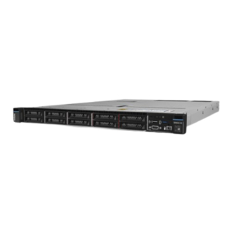
- Page 29 Server model with ten 2.5-inch drive bays Table 5. Components on the front of the server Callout Callout Drive status LED Drive activity LED Diagnostics panel USB 3.1 Gen 1 (5Gbps) connector External LCD connector XClarity Controller USB connector VGA connector (optional) Rack latch (right) Pull-out information tab Drive bays (10)
- Page 30 External LCD connector (reserved) XClarity Controller USB connector VGA connector (optional) Rack latch (right) Pull-out information tab Drive fillers (4) Rack latch (left) Note: For more information about each component, see “Front components overview” on page ThinkSystem SR635 V3 User Guide...
- Page 31 Server model with eight 2.5-inch drive bays (with LCD diagnostics panel assembly) Table 8. Components on the front of the server Callout Callout Drive status LED Drive activity LED LCD diagnostics panel assembly LCD diagnostics panel USB 3.1 Gen 1 (5Gbps) connector External LCD connector XClarity Controller USB connector VGA connector (optional)
- Page 32 Front components overview Integrated diagnostics panel The diagnostics panel is integrated in front I/O module on some models. For information about the controls and status LEDs on the diagnostics panel, see “Integrated diagnostics panel” on page 307. ThinkSystem SR635 V3 User Guide...
-
Page 33: Rear View
Pull-out information tab The Lenovo XClarity Controller network access label is attached on the pull-out information tab. The default Lenovo XClarity Controller hostname and the IPv6 Link Local Address (LLA) are provided on the tab. - Page 34 Figure 3. Rear view with 1 low profile PCIe adapter, 1 full height PCIe adapter, and 1 filler Table 12. Components on the rear of the server Callout Callout PCIe slot 1 on riser 1 assembly PCIe slot 2 on riser 1 assembly Power supply 1 Power supply 2 (optional) ThinkSystem SR635 V3 User Guide...
- Page 35 Table 12. Components on the rear of the server (continued) Callout Callout NMI button VGA connector USB 3.1 Gen 1 (5Gbps) connectors (3 DCIs) XClarity Controller network connector Ethernet connectors of the OCP module on the rear (optional, two or four connectors may be available) Figure 4.
- Page 36 The following illustration shows the rear view of the server model with two 7mm hot-swap rear drive bays and one PCIe slots. Depending on the model, your server might look slightly different from the illustration below. ThinkSystem SR635 V3 User Guide...
- Page 37 Table 17. Components on the rear of the server PCIe slot 1 on riser 1 assembly Rear 7mm drive bays (2) Power supply 2 (optional) Power supply 1 NMI button VGA connector USB 3.1 Gen 1 (5Gbps) connectors (3 DCIs) XClarity Controller network connector Ethernet connectors of the OCP module on the rear (optional, two or four connectors may be available)
-
Page 38: Top View
The hot-swap redundant power supply helps you avoid significant interruption to the operation of the system when a power supply fails. You can purchase a power supply option from Lenovo and install the power supply to provide power redundancy without turning off the server. - Page 39 Figure 8. Server top view for standard configurations Table 18. Component identification (Top view) Front backplane RAID flash power module Intrusion switch Fan modules Memory modules Processor and heat sink Riser assemblies note 1 Power supply units System board (system board assembly) Internal CFF HBA/RAID module Notes: 1.
-
Page 40: Front I/O Module
Figure 9. Server top view for the liquid cooling configuration Front I/O module The front I/O module of the server provides controls, connectors, and LEDs. The front I/O module varies by model. Depending on server models, your server supports the following front I/O modules. ThinkSystem SR635 V3 User Guide... -
Page 41: System-Board-Assembly Layout
FIO module For server model with • 4 x 2.5'' front drive bays • 8 x 2.5'' front drive bays • 10 x 2.5'' front drive bays • 16 EDSFF front drive bays Figure 10. FIO module type 1 • 10 x 2.5'' front drive bays Figure 11. - Page 42 Figure 13. System-board-assembly layout System I/O board Firmware and RoT security module Processor board Fan board PIB board • “System-board-assembly connectors” on page 33 • “System-board-assembly switches” on page 34 • “System-board-assembly LEDs” on page 297 ThinkSystem SR635 V3 User Guide...
-
Page 43: System-Board-Assembly Connectors
System-board-assembly connectors The following illustrations show the internal connectors on the system board. Figure 14. System-board-assembly connectors Table 20. System-board connectors Callout Callout NMI Button Rear USB Connector 1 MicroSD Connector VGA Connector Serial Port Connector Rear USB connector 2 Chapter 2 Server components... -
Page 44: System-Board-Assembly Switches
1. Before you change any switch settings or move any jumpers, turn off the server; then, disconnect all power cords and external cables. Review the following information: • https://pubs.lenovo.com/safety_documentation/ • “Installation Guidelines” on page 45 • “Handling static-sensitive devices” on page 48 • “Power off the server” on page 60 ThinkSystem SR635 V3 User Guide... - Page 45 2. Any system-board-assembly switch or jumper block that is not shown in the illustrations in this document are reserved. Figure 15. Switch block on the system board assembly Table 21. SW5 switch block on the system board assembly Switch Default position Description number Switch name...
-
Page 46: System Leds And Diagnostics Display
Reserved Reserved System LEDs and diagnostics display See the following section for information on available system LEDs and diagnostics display. For more information, refer to “Troubleshooting by system LEDs and diagnostics display” on page 292. ThinkSystem SR635 V3 User Guide... -
Page 47: Chapter 3. Parts List
2. Click Parts. 3. Enter the serial number to view a listing of parts for your server. It is highly recommended that you check the power summary data for your server using Lenovo Capacity Planner before purchasing any new parts. - Page 48 Tier 1 CRU at your request with no service agreement, you will be charged for the installation. • Tier 2 customer replaceable unit (CRU): You may install a Tier 2 CRU yourself or request Lenovo to install it, at no additional charge, under the type of warranty service that is designated for your server.
- Page 49 Table 22. Parts list (continued) Index Description Tier 1 CRU Tier 2 CRU Consuma- ble and Structural part 7mm drive backplane (top) √ 7mm drive backplane (bottom) √ 2.5-inch drive bay filler √ 2.5-inch drive √ 7mm drive bay filler √...
-
Page 50: Power Cords
The cord set should have the appropriate safety approvals for the country in which the equipment will be installed. • Power cords for a specific country or region are usually available only in that country or region. ThinkSystem SR635 V3 User Guide... -
Page 51: Chapter 4. Unboxing And Setup
They might be required to receive warranty service. Identify the server and access the Lenovo XClarity Controller This section contains instruction on how to identify your server and where to find the Lenovo XClarity Controller access information. - Page 52 Lenovo XClarity Controller network access label In addition, the Lenovo XClarity Controller network access label is attached to the pull-out information tab located near the lower right corner in the front of the chassis, with MAC address accessible with a pull.
-
Page 53: Server Setup Checklist
Figure 19. Service Label and QR code Server setup checklist Use the server setup checklist to ensure that you have performed all tasks that are required to set up your server. The server setup procedure varies depending on the configuration of the server when it was delivered. In some cases, the server is fully configured and you just need to connect the server to the network and an AC power source, and then you can power on the server. - Page 54 • You can press the power button. • The server can restart automatically after a power interruption. • The server can respond to remote power-on requests sent to the Lenovo XClarity Controller. Note: You can access the management processor interface to configure the system without powering on the server.
-
Page 55: Chapter 5. Hardware Replacement Procedures
• Do not attempt to lift an object that might be too heavy for you. If you have to lift a heavy object, read the following precautions carefully: – Make sure that you can stand steadily without slipping. – Distribute the weight of the object equally between your feet. © Copyright Lenovo 2023... -
Page 56: Safety Inspection Checklist
1 & IEC 60950-1, the standard for Safety of Electronic Equipment within the Field of Audio/Video, Information Technology and Communication Technology. Lenovo assumes you are qualified in the servicing of equipment and trained in recognizing hazards energy levels in products. Access to the equipment is by the use of a tool, lock and key, or other means of security, and is controlled by the authority responsible for the location. -
Page 57: System Reliability Guidelines
Click Power ➙ Power Cables to see all line cords. • Make sure that the insulation is not frayed or worn. 3. Check for any obvious non-Lenovo alterations. Use good judgment as to the safety of any non-Lenovo alterations. -
Page 58: Working Inside The Server With The Power On
• Do not touch solder joints, pins, or exposed circuitry. • Keep the device from others’ reach to prevent possible damages. Technical rules Refer to the below technical rules and limitations when you install the related server components. ThinkSystem SR635 V3 User Guide... -
Page 59: Memory Module Installation Rules And Order
Supported memory types For information on the types of memory module supported by this server, see “Memory” section in “Technical specifications” on page Information about optimizing memory performance and configuring memory is available at the Lenovo Press website: https://lenovopress.lenovo.com/servers/options/memory In addition, you can take advantage of a memory configurator, which is available at the following site: https://dcsc.lenovo.com/#/memory_configuration... -
Page 60: Pcie Slots And Adapters
Riser 1 assembly • Slot 1: PCIe x16 (x8, x4, x1), low-profile Riser 1 assembly • Slot 1: PCIe x16 (x8, x4, x1), low-profile Riser 2 assembly • Slot 3: PCIe x16 (x8, x4, x1), low-profile ThinkSystem SR635 V3 User Guide... - Page 61 Table 24. PCIe adapters supported and their locations (continued) Server rear view Supported types and slot location Riser 1 assembly • Slot 1: PCIe x16 (x8, x4, x1), low-profile Riser 1 assembly • Slot 1: PCIe x16 (x8, x4, x1), low-profile Riser 2 assembly •...
- Page 62 • For the low-profile + full-height configuration, the PCIe Ethernet adapters listed below cannot be installed on slot 1. – Lenovo ThinkSystem NetXtreme PCIe 1Gb 4-Port RJ45 Ethernet Adapter By Broadcom – Lenovo ThinkSystem I350-T4 PCIe 1Gb 4-Port RJ45 Ethernet Adapter By Intel –...
-
Page 63: Technical Rules For Drives
Configurations 100G PCIe adapters – 10 x 2.5" NVMe – ThinkSystem Broadcom 57508 100GbE QSFP56 2- port PCIe 4 Ethernet Adapter V2 w/ Active Fiber – 10 x 2.5" AnyBay cables – 8 x2.5'' SAS/SATA – Mellanox ConnectX-6 HDR100 IB/100GbE VPI 1-port –... -
Page 64: Thermal Rules
• Closed loop heat sink: CL • Performance fan: Perf • Standard fan: Std Typical configurations: sever models with front drive bays only This section provides thermal information for server models with front drive bays only. ThinkSystem SR635 V3 User Guide... - Page 65 Note: Among 10 x 2.5" configurations, only 10 x 2.5" NVMe (Gen 4) supports closed loop heat sink. 10 x 2.5" AnyBay (Gen 4/ Gen 5) and 10 x 2.5" NVMe (Gen 5) do not support it. Front bays Max. Processor group (A, B, E) Heat Ambi-...
- Page 66 The server supports the following GPU: • Low-profile, half-length, single-wide: – NVIDIA ® Heat Front bays Processor group installation type sink slot (s) Qty. lev- • 10 x 2.5" AnyBay 30°C Perf Perf 1, 2 • 10 x 2.5" NVMe ThinkSystem SR635 V3 User Guide...
- Page 67 Heat Front bays Processor group installation type sink slot (s) Qty. lev- 35°C Perf Perf 25°C E (9654/9654P processors only) Perf Perf • 10 x 2.5" SAS/SATA 30°C Perf Perf 1, 2, 3 • 8 x2.5'' SAS/SATA 35°C Perf Perf •...
- Page 68 2nd BMC manager port adapter • 4x2.5'' SAS/SATA installed • 4x2.5'' NVMe • No adapter installed in PCIe slot 1 • 4x2.5' AnyBay • No GPU adapter Perf 1, 2, 3, Other scenarios except the above 4, 5, 6, ThinkSystem SR635 V3 User Guide...
-
Page 69: Power On And Power Off The Server
• You can press the power button. • The server can restart automatically after a power interruption. • The server can respond to remote power-on requests sent to the Lenovo XClarity Controller. For information about powering off the server, see “Power off the server”... -
Page 70: Power Off The Server
Power off the server The server remains in a standby state when it is connected to a power source, allowing the Lenovo XClarity Controller to respond to remote power-on requests. To remove all power from the server (power status LED off), you must disconnect all power cables. -
Page 71: Install The Front 2.5-Inch Drive Backplane
Step 3. Grasp the backplane and carefully lift it out of the chassis. Figure 20. Removal of backplane for ten 2.5-inch hot-swap drives Step 4. Disconnect the cables from the backplane. See Chapter 6 “Internal cable routing” on page 217. After you finish If you are instructed to return the old backplane, follow all packaging instructions and use any packaging materials provided. -
Page 72: Remove The Front 16-Edsff Drive
• Prevent exposure to static electricity, which might lead to system halt and loss of data, by keeping static- sensitive components in their static-protective packages until installation, and handling these devices with an electrostatic-discharge wrist strap or other grounding system. Watch the procedure ThinkSystem SR635 V3 User Guide... -
Page 73: Install The Front 16-Edsff Drive Backplane
A video of this procedure is available at YouTube: https://www.youtube.com/playlist?list=PLYV5R7hVcs- DrpxDWLMfgtXO4O6BVYTim Procedure Step 1. Remove the top cover. See “Remove the top cover” on page 212. Step 2. Remove all the installed drives and drive cages from the drive bays. See “Remove a hot-swap EDSFF drive”... -
Page 74: Remove The Rear 2.5-Inch Drive Backplane
“Install a hot-swap EDSFF drive” on page 104. 2. Complete the parts replacement. See “Complete the parts replacement” on page 215. Remove the rear 2.5-inch drive backplane Use this information to remove the 2.5-inch rear drive backplane. ThinkSystem SR635 V3 User Guide... - Page 75 About this task Attention: • Read “Installation Guidelines” on page 45 “Safety inspection checklist” on page 46 to ensure that you work safely. • Power off the server and disconnect all power cords for this task. • Prevent exposure to static electricity, which might lead to system halt and loss of data, by keeping static- sensitive components in their static-protective packages until installation, and handling these devices with an electrostatic-discharge wrist strap or other grounding system.
-
Page 76: Install The Rear 2.5-Inch Drive Backplane
Touch the static-protective package that contains the rear backplane to any unpainted surface on the outside of the server. Then, take the rear backplane out of the package and place it on a static- protective surface. ThinkSystem SR635 V3 User Guide... - Page 77 Step 2. Align the rear backplane with the rear hot-swap drive cage and lower it into the rear hot-swap drive cage. Figure 26. Rear backplane installation Step 3. Connect the cables to the backplane. See Chapter 6 “Internal cable routing” on page 217.If the cable connectors come with protective dust caps, make sure to remove them before plugging in.
-
Page 78: Remove The 7Mm Drive Backplanes
235.If the cable connectors come with protective dust caps, make sure to remove them before plugging in. Remove the 7mm drive assembly from the rear chassis. See “Remove the 2.5-inch rear drive assembly” on page 169. ThinkSystem SR635 V3 User Guide... - Page 79 Step 2. Remove the 7mm drive backplane on the top. Figure 28. 7mm drive backplane removal (top) Remove the two screws as shown. Lift the top backplane up and put it aside. Step 3. Remove the 7mm drive backplane at the bottom. Figure 29.
-
Page 80: Install The 7Mm Drive Backplanes
Align the pin on the cage and slightly slide the bottom backplane into the cage until it is fully seated. Install the screw as shown. Step 3. Install the 7mm drive backplane on the top. ThinkSystem SR635 V3 User Guide... -
Page 81: Cmos Battery (Cr2032) Replacement
The following tips describe information that you must consider when removing the CMOS battery. • Lenovo has designed this product with your safety in mind. The lithium CMOS battery must be handled correctly to avoid possible danger. If you replace the CMOS battery, you must adhere to local ordinances or regulations for battery disposal. - Page 82 • To order replacement batteries, call your support center or business partner. For Lenovo support telephone numbers, see https://datacentersupport.lenovo.com/supportphonelist for your region support details.
-
Page 83: Install The Cmos Battery
The following tips describe information that you must consider when installing the CMOS battery. • Lenovo has designed this product with your safety in mind. The lithium CMOS battery must be handled correctly to avoid possible danger. If you replace the CMOS battery, you must adhere to local ordinances or regulations for battery disposal. - Page 84 • To order replacement batteries, call your support center or business partner. For Lenovo support telephone numbers, see for your region support https://datacentersupport.lenovo.com/supportphonelist details. Note: After you replace the CMOS battery, you must reconfigure the server and reset the system date and time.
-
Page 85: Edsff Cage Replacement
Step 1. Install any parts you removed and connect the cables. Step 2. Touch the static-protective package that contains the CMOS battery to any unpainted surface on the outside of the server. Then, take the CMOS battery out of the package. Step 3. -
Page 86: Install An Edsff Cage
2. If you are instructed to return the old EDSFF cage, follow all packaging instructions and use any packaging materials provided. Install an EDSFF cage Use this information to install an EDSFF cage. About this task ThinkSystem SR635 V3 User Guide... - Page 87 Attention: • Read “Installation Guidelines” on page 45 “Safety inspection checklist” on page 46 to ensure that you work safely. • Power off the server and disconnect all power cords for this task. • Prevent exposure to static electricity, which might lead to system halt and loss of data, by keeping static- sensitive components in their static-protective packages until installation, and handling these devices with an electrostatic-discharge wrist strap or other grounding system.
-
Page 88: Front I/O Module Replacement
• Prevent exposure to static electricity, which might lead to system halt and loss of data, by keeping static- sensitive components in their static-protective packages until installation, and handling these devices with an electrostatic-discharge wrist strap or other grounding system. ThinkSystem SR635 V3 User Guide... - Page 89 Watch the procedure A video of this procedure is available at YouTube: https://www.youtube.com/playlist?list=PLYV5R7hVcs- DrpxDWLMfgtXO4O6BVYTim Procedure Step 1. Remove the top cover. See “Remove the top cover” on page 212. Step 2. If the security bezel is installed, remove it. See “Remove the security bezel”...
-
Page 90: Install The Front I/O Module
Touch the static-protective package that contains the front I/O module to any unpainted surface on the outside of the server. Then, take the front I/O module out of the package and place it on a static-protective surface. Step 2. Install the front I/O module. ThinkSystem SR635 V3 User Guide... -
Page 91: Remove The Integrated Diagnostics Panel
Insert the front I/O module into the front chassis. Install the screws to secure the front I/O module in place. After you finish 1. Connect the front I/O cables to the system board. See “Front I/O module cable routing” on page 224. -
Page 92: Install The Integrated Diagnostics Panel
2. If you are instructed to return the old Integrated Diagnostics Panel assembly, follow all packaging instructions and use any packaging materials provided. Install the Integrated Diagnostics Panel assembly Use this information to install the diagnostics panel assembly. ThinkSystem SR635 V3 User Guide... - Page 93 About this task Attention: • Read “Installation Guidelines” on page 45 “Safety inspection checklist” on page 46 to ensure that you work safely. • Power off the server and disconnect all power cords for this task. • Prevent exposure to static electricity, which might lead to system halt and loss of data, by keeping static- sensitive components in their static-protective packages until installation, and handling these devices with an electrostatic-discharge wrist strap or other grounding system.
-
Page 94: Fan Board Replacement
Complete the parts replacement. See “Complete the parts replacement” on page 215. Fan board replacement Use this information to remove and install the fan board. Remove the fan board Use this information to remove the fan board. Attention: ThinkSystem SR635 V3 User Guide... - Page 95 • Read “Installation Guidelines” on page 45 “Safety inspection checklist” on page 46 to ensure that you work safely. • Power off the server and disconnect all power cords for this task. • Prevent exposure to static electricity, which might lead to system halt and loss of data, by keeping static- sensitive components in their static-protective packages until installation, and handling these devices with an electrostatic-discharge wrist strap or other grounding system.
-
Page 96: Install The Fan Board
1. Connect the fan board power cable, sideband cable, and other cables you disconnected before. See Chapter 6 “Internal cable routing” on page 217. 2. Install the system fans. See “Install a system fan” on page 210. 3. Complete the parts replacement. See “Complete the parts replacement” on page 215. ThinkSystem SR635 V3 User Guide... -
Page 97: Gpu Replacement
GPU replacement Use this information to remove and install a GPU adapter. • “Remove a GPU adapter” on page 87 • “Install a GPU adapter” on page 89 Remove a GPU adapter Use this information to remove a GPU adapter. About this task Attention: •... - Page 98 Note: If you are removing a GPU adapter on riser 3 assembly, slightly lift the riser assembly up, and disconnect cables from the system board (system board assembly) first. Step 3. Remove the GPU adapter from the riser bracket. ThinkSystem SR635 V3 User Guide...
-
Page 99: Install A Gpu Adapter
Figure 46. Removing the GPU adapter Rotate the GPU adapter retention latch to the open position. Grasp the GPU adapter by its edges and carefully pull it out of the PCIe slot. After you finish If you are instructed to return the component or optional device, follow all packaging instructions, and use any packaging materials for shipping that are supplied to you. - Page 100 (system board assembly). Carefully press the riser card straight into the slot until it is securely seated. Note: The following uses riser 1 assembly as an example for illustration. It is similar for other riser assemblies. See “Install a riser card” on page 181. ThinkSystem SR635 V3 User Guide...
-
Page 101: Server Replacement
Figure 48. Installing the riser assembly After you finish Complete the parts replacement. See “Complete the parts replacement” on page 215. Server replacement Follow instructions in this section to remove and install the server. Remove the server from rack Follow instructions in this section to remove the server from the rack. S036 18 - 32 kg (39 - 70 lb) 32 - 55 kg (70 - 121 lb) - Page 102 Loosen the two thumbscrews located on the front of the server to disengage it from the rack. Rack front Figure 49. Disengaging server from the rack Latches Thumbscrew Step 2. Hold the mounting ears on the front of the server; then, slide the server all the way out until it stops. ThinkSystem SR635 V3 User Guide...
- Page 103 Figure 50. Pulling out the server Mounting ears Step 3. Remove the server from the rack. CAUTION: Make sure three people are lifting the sever by holding the lift points Rack front Figure 51. Lifting up the server Lift points Chapter 5 Hardware replacement procedures...
-
Page 104: Install The Server To Rack
Follow instructions in this section to install the server to the rack. S036 18 - 32 kg (39 - 70 lb) 32 - 55 kg (70 - 121 lb) CAUTION: Use safe practices when lifting. S006 CAUTION: ThinkSystem SR635 V3 User Guide... - Page 105 When laser products (such as CD-ROMs, DVD drives, fiber optic devices, or transmitters) are installed, note the following: • Do not remove the covers. Removing the covers of the laser product could result in exposure to hazardous laser radiation. There are no serviceable parts inside the device. •...
- Page 106 Slowly lower the server down and make sure the other 3 nailheads on server’s left and right side slip into corresponding slots. Step 4. Slide the server into rack. ThinkSystem SR635 V3 User Guide...
- Page 107 Figure 55. Installing the server into the rack Latch Push up the latches on the rails. Push the server all the way into the rack until both latches lock into position with a click. Chapter 5 Hardware replacement procedures...
- Page 108 Secure the server to the front of the rack. Fasten the two thumbscrews located on the front of the server. Rack front Figure 57. Securing the server to the front of the rack Latches Thumbscrew After you finish ThinkSystem SR635 V3 User Guide...
-
Page 109: Hot-Swap Drive Replacement
1. Reconnect the power cords and any cables that you removed. 2. Power on the server and any peripheral devices. See “Power on the server” on page 3. Update the server configuration. See “Complete the parts replacement” on page 215. Hot-swap drive replacement Use this information to remove and install a hot-swap drive. -
Page 110: Install A 2.5-Inch Hot-Swap Drive
And then, take the drive out of the package and place it on a static-protective surface. Step 2. Remove the drive filler from the drive bay and keep the drive filler in a safe place. ThinkSystem SR635 V3 User Guide... - Page 111 After you finish 1. Reinstall the security bezel if you have removed it. See “Install the security bezel” on page 184. 2. Use the Lenovo XClarity Provisioning Manager to configure the RAID if necessary. For more information, Chapter 5 Hardware replacement procedures...
-
Page 112: Remove A Hot-Swap Edsff Drive
Watch the procedure A video of this procedure is available at YouTube: https://www.youtube.com/playlist?list=PLYV5R7hVcs- DrpxDWLMfgtXO4O6BVYTim Procedure Step 1. If the security bezel is installed, remove it first. See “Remove the security bezel” on page 183. ThinkSystem SR635 V3 User Guide... - Page 113 Step 2. Remove the EDSFF drive cage cover. Figure 60. EDSFF drive cage cover removal Open the handle as shown. Grasp the handle and remove the drive cage cover. Step 3. Remove the EDSFF drive. Figure 61. EDSFF drive removal Slide the release latch as shown to open the drive tray handle.
-
Page 114: Install A Hot-Swap Edsff Drive
Remove the drive filler from the drive bay and keep the drive filler in a safe place. Figure 62. Remove an EDSFF drive filler Press the latch down to disengage the drive clip from the cage. Pull and slide the filler out. ThinkSystem SR635 V3 User Guide... - Page 115 After you finish 1. Reinstall the security bezel if you have removed it. See “Install the security bezel” on page 184. 2. Use the Lenovo XClarity Provisioning Manager to configure the RAID if necessary. For more information, see: https://sysmgt.lenovofiles.com/help/topic/lxpm_frontend/lxpm_product_page.html Chapter 5...
-
Page 116: Hot-Swap Power Supply Unit Replacement
Press down the stop bracket and rotate it to the open position. Rotate the CMA out of the way to gain access to the power supply unit. Note: Your CMA kit might look different from the illustration. ThinkSystem SR635 V3 User Guide... - Page 117 Figure 65. Adjusting the CMA Step 2. Disconnect the power cord from the hot-swap power supply unit and the electrical outlet. • For AC power supply units, disconnect both ends of the power cord and keep it in an ESD-safe place.
-
Page 118: Install A Hot-Swap Power Supply
If you are replacing the existing power supply unit with a new one: • Use Lenovo Capacity Planner to calculate the required power capacity for what is configured for your server. More information about Lenovo Capacity Planner is available at: https://datacentersupport.lenovo.com/solutions/lnvo-lcp... - Page 119 • Read “Installation Guidelines” on page 45 “Safety inspection checklist” on page 46 to ensure that you work safely. • Prevent exposure to static electricity, which might lead to system halt and loss of data, by keeping static- sensitive components in their static-protective packages until installation, and handling these devices with an electrostatic-discharge wrist strap or other grounding system.
-
Page 120: Internal Cff Hba/Raid Adapter Replacement
Remove the internal CFF HBA/RAID adapter Use this information to remove the internal CFF HBA/RAID adapter. About this task Attention: • Read “Installation Guidelines” on page 45 “Safety inspection checklist” on page 46 to ensure that you work safely. ThinkSystem SR635 V3 User Guide... -
Page 121: Install The Internal Cff Hba/Raid Adapter
• Power off the server and disconnect all power cords for this task. • Prevent exposure to static electricity, which might lead to system halt and loss of data, by keeping static- sensitive components in their static-protective packages until installation, and handling these devices with an electrostatic-discharge wrist strap or other grounding system. -
Page 122: Intrusion Switch Replacement
The intrusion switch informs you that the server cover is not properly installed or closed by creating an event in the system event log (SEL). Remove an intrusion switch Use this information to remove an intrusion switch. ThinkSystem SR635 V3 User Guide... - Page 123 About this task Attention: • Read “Installation Guidelines” on page 45 “Safety inspection checklist” on page 46 to ensure that you work safely. • Power off the server and disconnect all power cords for this task. • Prevent exposure to static electricity, which might lead to system halt and loss of data, by keeping static- sensitive components in their static-protective packages until installation, and handling these devices with an electrostatic-discharge wrist strap or other grounding system.
- Page 124 Slide the intrusion switch as shown to remove it. Step 4. Re-install the number 4 fan. After you finish If you are instructed to return the old intrusion switch, follow all packaging instructions and use any packaging materials that are provided. ThinkSystem SR635 V3 User Guide...
-
Page 125: Install An Intrusion Switch
Install an intrusion switch Use this information to install an intrusion switch. About this task Attention: • Read “Installation Guidelines” on page 45 “Safety inspection checklist” on page 46 to ensure that you work safely. • Power off the server and disconnect all power cords for this task. •... - Page 126 Connect the cable of the intrusion switch to the intrusion switch connector on the system board. “Intrusion switch” on page 226. Step 5. Re-install the number 4 fan. After you finish Complete the parts replacement. See “Complete the parts replacement” on page 215. ThinkSystem SR635 V3 User Guide...
-
Page 127: Lenovo Neptune (Tm) Liquid Assisted Cooling Module Replacement (Trained Technicians Only)
(LACM). This module can also be called the closed loop cooling module. Important: • This task must be operated by trained technicians that are certified by Lenovo Service. Do no attempt to remove or install it without proper training and qualification. - Page 128 1. Press the release tab to release the connector. 2. Disengage the connector from the cable socket. Figure 72. Disconnecting cables from the system board assembly Step 4. Route the leak detection cable out of the cable clips on the leak detection module. ThinkSystem SR635 V3 User Guide...
- Page 129 Step 5. Re-install the module handle (LACM heat sink bracket) to the LACM. Place the module handle (LACM heat sink bracket) evenly on the LACM and align screw holes. Tighten the five screws. Ensure that the screws are secured in place. Step 6.
-
Page 130: Install The Lenovo Neptune (Tm) Liquid Assisted Cooling Module
Follow instructions in this section to install the Lenovo Neptune (TM) liquid assisted cooling module (LACM). Important: This task must be operated by trained technicians that are certified by Lenovo Service. Do no attempt to remove or install it without proper training and qualification. - Page 131 Ensure that the module handle (LACM heat sink bracket) is installed when removing or installing the LACM. Do not touch the radiator fins. Touching the radiator fins might damage the LACM. Prepare the following screwdrivers to ensure you can install and remove the corresponding screws properly. Torque screwdriver type list Screw Type Torx T20 screwdriver...
- Page 132 Make sure you have an alcohol cleaning pad available. Attention: If there is any old thermal grease on the processors, gently clean the top of the processors with an alcohol cleaning pad. Step 5. Install the LACM to the system board assembly. ThinkSystem SR635 V3 User Guide...
- Page 133 Align the triangular mark on the cold plate assembly label with the triangular mark on the processor carrier and processor. Install the LACM onto the processor-carrier. Press the carrier into place until the clips at all four corners engage. Fully tighten the eight Torx T20 nuts in the installation sequence shown on the cold plate assembly and the radiator.
-
Page 134: Memory Module Replacement
61 “Power/Sideband cable routing” on page 244. 2. Complete the parts replacement. See “Complete the parts replacement” on page 215. Memory module replacement Use the following procedures to remove and install a memory module. ThinkSystem SR635 V3 User Guide... -
Page 135: Remove A Memory Module
Remove a memory module Use this information to remove a memory module. About this task Attention: • Read “Installation Guidelines” on page 45 “Safety inspection checklist” on page 46 to ensure that you work safely. • Power off the server and peripheral devices and disconnect the power cords and all external cables. See “Power off the server”... -
Page 136: Install A Memory Module
2. If you are instructed to return the component or optional device, follow all packaging instructions, and use any packaging materials for shipping that are supplied to you. Install a memory module Follow instructions in this section to install a memory module. About this task Attention: ThinkSystem SR635 V3 User Guide... - Page 137 Important: Remove or install memory modules for one processor at a time. Firmware and driver download: You might need to update the firmware or driver after replacing a component. • Go to https://datacentersupport.lenovo.com/products/servers/thinksystem/sr635v3/7d9h//downloads/driver- to see the latest firmware and driver updates for your server. list/ • Go to “Update the firmware”...
- Page 138 In this case, open the retaining clips, remove the memory module, and then reinsert it. After you finish • Complete the parts replacement. See “Complete the parts replacement” on page 215. ThinkSystem SR635 V3 User Guide...
-
Page 139: M.2 Backplane And M.2 Drive Replacement
M.2 backplane and M.2 drive replacement Use this information to remove and install the M.2 backplane and M.2 drive (an assembled M.2 backplane and M.2 drive is also known as M.2 module). The server supports two types of M.2 backplanes. The removal and installation methods are similar. Note: The M.2 adapters and modules are also referred to as enablement kits. - Page 140 Slide the retainer backward to loosen the M.2 drive from the M.2 backplane. Rotate the M.2 drive away from the M.2 backplane. Pull the M.2 drive away from the connector at an angle of approximately 30 degrees. ThinkSystem SR635 V3 User Guide...
- Page 141 Step 3. Remove the M.2 module from the chassis. Figure 78. M.2 module removal Loosen the screw. Release the M.2 backplane from the pin and carefully lift the M.2 backplane out from the chassis. Step 4. Disconnect all M.2 cables from the system board. See “M.2 drive backplane cable routing”...
-
Page 142: Adjust The Retainer On The M.2 Backplane
Press both sides of the retainer. Step 6. Slide the retainer backwards until it is seated in place. Install the M.2 backplane and M.2 drive Use this information to install the M.2 backplane and M.2 drive. ThinkSystem SR635 V3 User Guide... - Page 143 About this task Attention: • Read “Installation Guidelines” on page 45 “Safety inspection checklist” on page 46 to ensure that you work safely. • Power off the server and disconnect all power cords for this task. • Prevent exposure to static electricity, which might lead to system halt and loss of data, by keeping static- sensitive components in their static-protective packages until installation, and handling these devices with an electrostatic-discharge wrist strap or other grounding system.
- Page 144 Connect the cables to the M.2 backplane and system board. See “M.2 drive backplane cable routing” on page 239. If your server installs a M.2 PCIe 3.0 backplane, see the following to connect the cables: ThinkSystem SR635 V3 User Guide...
-
Page 145: Microsd Card Replacement
1. Complete the parts replacement. See “Complete the parts replacement” on page 215. 2. Use the Lenovo XClarity Provisioning Manager to configure the RAID. For more information, see: https://sysmgt.lenovofiles.com/help/topic/lxpm_frontend/lxpm_product_page.html MicroSD card replacement Follow the instructions in this section to remove and install the MicroSD card. - Page 146 1. Install a replacement unit. See “Install the MicroSD card” on page 137. 2. If you are instructed to return the old RAID flash power module, follow all packaging instructions and use any packaging materials that are provided. ThinkSystem SR635 V3 User Guide...
-
Page 147: Install The Microsd Card
Install the MicroSD card Follow the instructions in this section to install the MicroSD card. About this task Attention: • Read “Installation Guidelines” on page 45 “Safety inspection checklist” on page 46 to ensure that you work safely. • Power off the server and disconnect all power cords for this task. •... -
Page 148: Ocp Module Replacement
A video of this procedure is available at YouTube: https://www.youtube.com/playlist?list=PLYV5R7hVcs- DrpxDWLMfgtXO4O6BVYTim Procedure Figure 85. OCP module removal Step 1. Loosen the thumbscrew that secures the adapter. Step 2. Pull out the OCP module by its handle on the left as shown. ThinkSystem SR635 V3 User Guide... -
Page 149: Install The Ocp Module
After you finish Install a new OCP module or a card filler. See “Install the OCP module” on page 139. Install the OCP module Use this information to install the OCP module. About this task Attention: • Read “Installation Guidelines” on page 45 “Safety inspection checklist”... -
Page 150: Pcie Adapter Replacement
• Use any documentation that comes with the PCIe adapter, and follow the instructions and those in this topic. Remove a PCIe adapter Use this information to remove a PCIe adapter. About this task Attention: ThinkSystem SR635 V3 User Guide... - Page 151 • Read “Installation Guidelines” on page 45 “Safety inspection checklist” on page 46 to ensure that you work safely. • Power off the server and disconnect all power cords for this task. • Prevent exposure to static electricity, which might lead to system halt and loss of data, by keeping static- sensitive components in their static-protective packages until installation, and handling these devices with an electrostatic-discharge wrist strap or other grounding system.
-
Page 152: Install A Pcie Adapter
Then, take the PCIe adapter out of the package and place it on a static- protective surface. Step 2. Locate the correct PCIe slot for the PCIe adapter. For information about the PCIe slots and supported PCIe adapters, see “Rear view” on page ThinkSystem SR635 V3 User Guide... -
Page 153: Power Supply Unit Air Baffle Replacement
Step 3. Install the PCIe adapter and secure it to the riser assembly. Figure 89. PCIe adapter installation into the LP-FH riser assembly Align the PCIe adapter with the PCIe slot on the riser card. Then, carefully press the PCIe adapter straight into the slot until it is securely seated and its bracket is secured. - Page 154 Loosen the screw on the air baffle. Lift the air baffle out of the chassis. After you finish If you are instructed to return the old air baffle, follow all packaging instructions and use any packaging materials that are provided. ThinkSystem SR635 V3 User Guide...
-
Page 155: Install A Power Supply Unit Air Baffle Baffle
Install a power supply unit air baffle baffle Use this information to understand how to install a power supply unit air baffle. About this task S014 CAUTION: Hazardous voltage, current, and energy levels might be present. Only a qualified service technician is authorized to remove the covers where the label is attached. - Page 156 • Properly route and secure the cables in the server. Refer to detailed cable routing information for each component in Chapter 6 “Internal cable routing” on page 217. • Complete the parts replacement. See “Complete the parts replacement” on page 215. ThinkSystem SR635 V3 User Guide...
-
Page 157: Processor And Heat Sink Replacement
117. Important: • This task must be operated by trained technicians that are certified by Lenovo Service. Do no attempt to remove or install it without proper training and qualification. • Before replacing a processor, check the current PSB fuse policy. See Service process before replacement Service process for updating PSB fuse state. -
Page 158: Remove A Heat Sink
“Install a processor” on page 153 • “Install a heat sink” on page 151 Remove a heat sink Use this information to remove a heat sink. This procedure must be executed by a trained technician. About this task S002 ThinkSystem SR635 V3 User Guide... - Page 159 CAUTION: The power-control button on the device and the power switch on the power supply do not turn off the electrical current supplied to the device. The device also might have more than one power cord. To remove all electrical current from the device, ensure that all power cords are disconnected from the power source.
-
Page 160: Remove A Processor
Watch the procedure A video of this procedure is available at YouTube: https://www.youtube.com/playlist?list=PLYV5R7hVcs- DrpxDWLMfgtXO4O6BVYTim Procedure ThinkSystem SR635 V3 User Guide... -
Page 161: Install A Heat Sink
Figure 94. Processor removal Step 1. Use a Torx T20 screwdriver to loosen the captive screw. Step 2. Slightly lift up the retention frame in the direction shown. Step 3. Slightly lift up the rail frame in the direction shown. The processor in the rail frame is spring- loaded. - Page 162 Apply new thermal grease on the top of the processor with a syringe by forming four uniformly spaced dots, while each dot consists of about 0.1 ml of thermal grease. Figure 95. Applying thermal grease Step 3. Install the heat sink. ThinkSystem SR635 V3 User Guide...
-
Page 163: Install A Processor
• See for a list of processors supported for your server. All processors on https://serverproven.lenovo.com the system board (system board assembly) must have the same speed, number of cores, and frequency. • Before you install a new processor or replacement processor, update your system firmware to the latest level. -
Page 164: Power Inverter Board (Pib) Replacement
• Prevent exposure to static electricity, which might lead to system halt and loss of data, by keeping static- sensitive components in their static-protective packages until installation, and handling these devices with an electrostatic-discharge wrist strap or other grounding system. ThinkSystem SR635 V3 User Guide... -
Page 165: Install The Pib Board
Before removing the PIB board: 1. Remove the top cover. See “Remove the top cover” on page 212. 2. Pull out the power supplies slightly. Ensure that they are disconnected from the system board. 3. Remove the system board assembly out of the chassis. See “Remove the system I/O board or processor board”... -
Page 166: Rack Latches Replacement
2. Push the power supplies into the bays until they click into place. 3. Complete the parts replacement. See “Complete the parts replacement” on page 215. Rack latches replacement Use this information to remove and install the rack latches. ThinkSystem SR635 V3 User Guide... -
Page 167: Remove The Rack Latches
Remove the rack latches Use this information to remove the rack latches. About this task Attention: Read “Installation Guidelines” on page 45 “Safety inspection checklist” on page 46 to ensure that you work safely. Watch the procedure A video of this procedure is available at YouTube: https://www.youtube.com/playlist?list=PLYV5R7hVcs- DrpxDWLMfgtXO4O6BVYTim Procedure... -
Page 168: Install The Rack Latches
Touch the static-protective package that contains the rack latches to any unpainted surface on the outside of the server. Then, take the rack latches out of the package and place them on a static- protective surface. ThinkSystem SR635 V3 User Guide... -
Page 169: Raid Flash Power Module Replacement
RAID flash power module replacement The RAID flash power module protects the cache memory on the installed RAID adapter. You can purchase a RAID flash power module from Lenovo. Use this information to remove and install a RAID flash power module. -
Page 170: Chassis
Watch the procedure A video of this procedure is available at YouTube: https://www.youtube.com/playlist?list=PLYV5R7hVcs- DrpxDWLMfgtXO4O6BVYTim ThinkSystem SR635 V3 User Guide... -
Page 171: Chassis
Procedure Step 1. Remove the top cover. See “Remove the top cover” on page 212. Step 2. Disconnect the cable of the RAID flash power module. Step 3. Remove the RAID flash power module on the chassis. Figure 105. Removal of the RAID flash power module on the chassis Open the retention clip on the holder of the RAID flash power module. - Page 172 Step 2. If the server comes with a tray that covers the place of the RAID flash power module on the chassis, remove it first. Figure 107. Tray removal ThinkSystem SR635 V3 User Guide...
- Page 173 Step 3. If the server does not have a RAID flash power module holder on the chassis, install one first. Figure 108. RAID flash power module holder installation Step 4. Install the RAID flash power module on the chassis. Figure 109. Installation of the RAID flash power module on the chassis Open the retention clip on the holder.
-
Page 174: Remove The Raid Flash Power Module On The System Board Tray
Figure 110. Removal of the RAID flash power module on the system board tray Open the retention clip on the holder of the RAID flash power module. Take the RAID flash power module out of the holder. ThinkSystem SR635 V3 User Guide... -
Page 175: Install The Raid Flash Power Module On The System Board Tray
Step 4. Remove the RAID flash power module holder as shown if necessary. Figure 111. RAID flash power module holder removal After you finish If you are instructed to return the old RAID flash power module, follow all packaging instructions and use any packaging materials that are provided. - Page 176 Figure 112. Tray removal Step 3. If the server does not have a RAID flash power module holder on the system board tray, install one first. Figure 113. RAID flash power module holder installation ThinkSystem SR635 V3 User Guide...
-
Page 177: Remove The Raid Flash Power Module On The Riser
Step 4. Install the RAID flash power module on the system board tray. Figure 114. Installation of the RAID flash power module on the system board tray Open the retention clip on the holder. Put the RAID flash power module into the holder and press it down to secure it into the holder. -
Page 178: Install The Raid Flash Power Module On The Riser
Watch the procedure A video of this procedure is available at YouTube: https://www.youtube.com/playlist?list=PLYV5R7hVcs- DrpxDWLMfgtXO4O6BVYTim Procedure ThinkSystem SR635 V3 User Guide... -
Page 179: Rear Drive Assembly Replacement
Step 1. Touch the static-protective package that contains the RAID flash power module to any unpainted surface on the outside of the server. Then, take the RAID flash power module out of the package and place it on a static-protective surface. Step 2. - Page 180 • The connectors on your system board assembly might look different from those in the illustration, but the removal procedure is the same. 1. Press the release tab to release the connector. 2. Disengage the connector from the cable socket. Figure 117. Disconnecting cables from the system board assembly ThinkSystem SR635 V3 User Guide...
-
Page 181: Install The 2.5-Inch Rear Drive Assembly
Step 4. Hold the two blue touch points and directly lift the rear drive cage out of the chassis. Figure 118. Hot-swap rear drive cage removal Step 5. If the rear backplane is reused, remove the rear backplane. See “Remove the rear 2.5-inch drive backplane”... - Page 182 Press the tab on one side to disengage the air baffle. Lift the air baffle to remove it from drive cage. Step 3. Align the rear backplane with the rear drive cage and lower it into the rear drive cage. Figure 120. Rear backplane installation ThinkSystem SR635 V3 User Guide...
- Page 183 Step 4. Connect the cables to the backplane. Step 5. Install the air baffle into the rear drive cage as shown. Figure 121. Air baffle installation Align the air baffle edge with the notch on the drive cage. Press the air baffle down and make sure that it is seated in place. Step 6.
-
Page 184: Remove The 7Mm Rear Drive Assembly
• The connectors on your system board assembly might look different from those in the illustration, but the removal procedure is the same. 1. Press the release tab to release the connector. 2. Disengage the connector from the cable socket. ThinkSystem SR635 V3 User Guide... -
Page 185: Install The 7Mm Rear Drive Assembly
Figure 123. Disconnecting cables from the system board assembly Step 4. Lift the rear drive cage out of the chassis. Figure 124. Hot-swap rear drive cage removal Step 5. If the rear backplane is reused, remove the rear backplane. See “Remove the 7mm drive backplanes”... -
Page 186: Riser Card Replacement
100. 2. Complete the parts replacement. See “Complete the parts replacement” on page 215. Riser card replacement Use this information to remove and install a riser card. There are different types of riser assembly configurations. ThinkSystem SR635 V3 User Guide... - Page 187 Table 27. Types of riser bracket The overview of riser brackets Low profile (LP) Low profile-full height (LP-FH) Low profile-a filler Chapter 5 Hardware replacement procedures...
-
Page 188: Remove A Riser Card
Watch the procedure A video of this procedure is available at YouTube: https://www.youtube.com/playlist?list=PLYV5R7hVcs- DrpxDWLMfgtXO4O6BVYTim Procedure Step 1. Remove the top cover. See “Remove the top cover” on page 212. ThinkSystem SR635 V3 User Guide... - Page 189 Step 2. If there is any PCIe adapter installed on the riser card, record the cable connections first. Then, disconnect all cables from the PCIe adapter. Step 3. Press the two latches on both ends at the same time, and carefully lift it out of the chassis by the two latches.
- Page 190 1. If you are instructed to return the old riser card, follow all packaging instructions and use any packaging materials that are provided. 2. Remove the rear wall bracket if you would like to install a non-LP-FH riser assembly. ThinkSystem SR635 V3 User Guide...
-
Page 191: Install A Riser Card
Figure 128. Rear wall bracket removal Install a riser card Use this information to install a riser card. About this task The riser assembly you want to install might be different from the following illustrations, but the installation method is the same. The following takes the LPFH riser assembly as an example. Attention: •... - Page 192 Then, refer to your note to reconnect any cables of the PCIe adapters on the riser card. Or you can refer to the Chapter 6 “Internal cable routing” on page 217 and locate the cable routing information for your configuration options. ThinkSystem SR635 V3 User Guide...
-
Page 193: Security Bezel Replacement
Step 4. Position the riser assembly on the chassis. Align the plastic clip and two pins on the bracket with the guide pin and two holes on the chassis, and align the riser card with the riser slot on the system board. -
Page 194: Install The Security Bezel
Attention: Before you ship the rack with the server installed, reinstall and lock the security bezel into place. Figure 132. Security bezel removal Press the release latch. Rotate the security bezel outward to remove it from the chassis. Install the security bezel Use this information to install the security bezel. ThinkSystem SR635 V3 User Guide... - Page 195 About this task Attention: Read “Installation Guidelines” on page 45 “Safety inspection checklist” on page 46 to ensure that you work safely. Watch the procedure A video of this procedure is available at YouTube: https://www.youtube.com/playlist?list=PLYV5R7hVcs- DrpxDWLMfgtXO4O6BVYTim Procedure Step 1. If you have removed the rack latches, reinstall them. See “Install the rack latches”...
- Page 196 Press and hold the blue release latch. Rotate the security bezel inward until the left side clicks into place. Step 4. Use the key to lock the security bezel to the closed position. Figure 135. Locking the security bezel ThinkSystem SR635 V3 User Guide...
-
Page 197: Serial Port Module Replacement
Serial port module replacement Use this information to remove and install a serial port module. Remove a serial port module Use this information to remove a serial port module. About this task Attention: • Read “Installation Guidelines” on page 45 “Safety inspection checklist”... - Page 198 Remove the serial port module from the riser bracket. Step 5. (Optional) If you need to replace the serial port bracket, use a 5 mm wrench to disassemble the serial port cable from the bracket. ThinkSystem SR635 V3 User Guide...
-
Page 199: Install A Serial Port Module
Figure 138. Disassembling the serial port module Loosen the two screws. Pull out the serial port cable from the bracket. After you finish 1. Install a new serial port module, a PCIe adapter, or a PCIe slot bracket to cover the place. See “Install a serial port module”... - Page 200 Open the retention latch on the riser cage. Install the serial port module to the riser bracket. Close the retention latch and ensure that the serial port module is securely installed. Step 4. Install the riser assembly to the server. ThinkSystem SR635 V3 User Guide...
-
Page 201: System Board Assembly Replacement
Figure 141. Installing the riser assembly Step 5. Connect the cable of the serial port module to the serial-port-module connector on the system board. For the location of the serial-port-module connector, refer to “System-board-assembly connectors” on page After you finish 1. - Page 202 • This task must be operated by trained technicians that are certified by Lenovo Service. Do no attempt to remove or install it without proper training and qualification. • If you need to replace a processor board and a firmware and RoT security module together, do the following: –...
- Page 203 Figure 142. System-board-assembly layout Firmware and RoT security module System I/O board Processor board Fan board PIB board For the installation and removal of the fan board and the PIB board, see “Fan board replacement” on page 84 “Power inverter board (PIB) replacement” on page 154.
-
Page 204: Remove The Firmware And Rot Security
Follow instructions in this section to remove the ThinkSystem V3 Firmware and Root of Trust Security Module (firmware and RoT security module). About this task Important: This task must be operated by trained technicians that are certified by Lenovo Service. Do no attempt to remove or install it without proper training and qualification. Attention: •... -
Page 205: Install The Firmware And Rot Security
(firmware and RoT security module). About this task Important: This task must be operated by trained technicians that are certified by Lenovo Service. Do no attempt to remove or install it without proper training and qualification. (Lenovo Trained technicians only) After replacing the firmware and RoT security module, update the UEFI firmware to the specific version supported by the server. - Page 206 3. Update the UEFI, XCC and LXPM firmware to the specific version supported by the server. See Tip for replacing a Firmware and RoT Security Module 4. Perform OneCLI commands to restore the UEFI settings. See OneCLI commands that restore configuration settings ThinkSystem SR635 V3 User Guide...
- Page 207 OneCli.exe config set TrustedComputingGroup.HideTPMfromOS "Yes" --imm <userid>:<password>@<ip_address> --override where: • <userid>:<password> are the credentials used to access the BMC (Lenovo XClarity Controller interface) of your server. The default user ID is USERID, and the default password is PASSW0RD (zero, not an uppercase o) •...
- Page 208 Follow the procedure below to see the TPM firmware version: From Lenovo XClarity Provisioning Manager 1. Start the server and press the key specified in the on-screen instructions to display the Lenovo XClarity Provisioning Manager interface. (For more information, see the “Startup” section in the LXPM documentation compatible with your server at https://sysmgt.lenovofiles.com/help/topic/lxpm_frontend/...
-
Page 209: Remove The System I/O Board Or Processor
About this task Important: • This task must be operated by trained technicians that are certified by Lenovo Service. Do no attempt to remove or install it without proper training and qualification. • When replacing the system board assembly, always update the server with the latest firmware or restore the pre-existing firmware. - Page 210 The device also might have more than one power cord. To remove all electrical current from the device, ensure that all power cords are disconnected from the power source. Watch the procedure A video of this procedure is available at YouTube: https://www.youtube.com/playlist?list=PLYV5R7hVcs- DrpxDWLMfgtXO4O6BVYTim Procedure ThinkSystem SR635 V3 User Guide...
- Page 211 Step 1. Make preparation for this task. Record all system configuration information, such as Lenovo XClarity Controller IP addresses, vital product data, and the machine type, model number, serial number, Universally Unique Identifier, and asset tag of the server. Save the system configuration to an external device with Lenovo XClarity Essentials.
- Page 212 194. If you are going to replace the processor board, go to next step directly. Step 5. (Optional) Remove the MicroSD card. See “Remove the MicroSD card” on page 135. Step 6. Separate the system I/O board from the processor board. ThinkSystem SR635 V3 User Guide...
-
Page 213: Install The System I/O Board Or Processor
Follow instructions in this section to install the system I/O board or processor board. About this task Important: • This task must be operated by trained technicians that are certified by Lenovo Service. Do no attempt to remove or install it without proper training and qualification. Chapter 5... - Page 214 • If you are going to replace the system I/O board and reuse the processor board, install a new system I/O board onto the processor board. • If you are going to replace the processor board and reuse the system I/O board, install the existing system I/O board onto a new processor board. ThinkSystem SR635 V3 User Guide...
- Page 215 Figure 148. Installing the system I/O board onto the processor board Align the system I/O board with the connector on the processor board, and use both hands to push the system I/O board and slightly insert it into the connector. Note: To prevent the contact of the system I/O board from damage, ensure that the system I/ O board is aligned correctly with the connector on the processor board, and remains as horizontal as possible during the insertion.
- Page 216 “Install a memory module” on page 126 • “Install the CMOS battery” on page 73 • “Install the RAID flash power module on the chassis” on page 161 • “Install a system fan” on page 210 ThinkSystem SR635 V3 User Guide...
- Page 217 Using Lenovo XClarity Provisioning Manager Steps: 1. Start the server and press the key according to the on-screen instructions. The Lenovo XClarity Provisioning Manager interface is displayed by default. 2. Choose System Summary. The “System Summary” tab page is displayed.
-
Page 218: System Fan Replacement
Using Lenovo XClarity Essentials OneCLI commands • Updating machine type onecli config set SYSTEM_PROD_DATA.SysInfoProdName <m/t_model> [access_method] • Updating serial number onecli config set SYSTEM_PROD_DATA.SysInfoSerialNum <s/n> [access_method] • Updating system model onecli config set SYSTEM_PROD_DATA.SysInfoProdIdentifier <system model> [access_method] onecli config set SYSTEM_PROD_DATA.SysInfoProdIdentifierEx <system model> --override [access_method] •... -
Page 219: Remove A System Fan
Remove a system fan Use this information to remove a system fan. You can remove a hot-swap fan without powering off the server, which helps you avoid significant interruption to the operation of the system. About this task S033 CAUTION: Hazardous energy present. -
Page 220: Install A System Fan
About this task S033 CAUTION: Hazardous energy present. Voltages with hazardous energy might cause heating when shorted with metal, which might result in spattered metal, burns, or both. ThinkSystem SR635 V3 User Guide... - Page 221 S017 CAUTION: Hazardous moving fan blades nearby. Keep fingers and other body parts away. Attention: • Read “Installation Guidelines” on page 45 “Safety inspection checklist” on page 46 to ensure that you work safely. • Prevent exposure to static electricity, which might lead to system halt and loss of data, by keeping static- sensitive components in their static-protective packages until installation, and handling these devices with an electrostatic-discharge wrist strap or other grounding system.
-
Page 222: Top Cover Replacement
A video of this procedure is available at YouTube: https://www.youtube.com/playlist?list=PLYV5R7hVcs- DrpxDWLMfgtXO4O6BVYTim Procedure Step 1. If the server is installed in a rack, remove the server from the rack. See the Rack Installation Guide that comes with the rail kit for your server. ThinkSystem SR635 V3 User Guide... -
Page 223: Install The Top Cover
Step 2. Remove the top cover. Attention: Handle the top cover carefully. Dropping the top cover with the cover latch open might damage the cover latch. Figure 152. Top cover removal Use a screwdriver to turn the cover lock to the unlocked position as shown. Press the release button on the cover latch. - Page 224 • All cables, adapters, and other components are installed and seated correctly and that you have not left loose tools or parts inside the server. • All internal cables are connected and routed correctly. See Chapter 6 “Internal cable routing” on page 217. ThinkSystem SR635 V3 User Guide...
-
Page 225: Complete The Parts Replacement
Step 2. Install the top cover to your server. Attention: Handle the top cover carefully. Dropping the top cover with the cover latch open might damage the cover latch. Figure 153. Top cover installation Ensure that the cover latch is in the open position. Lower the top cover onto the chassis until both sides of the top cover engage the guides on both sides of the chassis. - Page 226 • Update the UEFI configuration. See https://pubs.lenovo.com/uefi-overview.html • Reconfigure the disk arrays if you have installed or removed a hot-swap drive or a RAID adapter. See for the LXPM https://sysmgt.lenovofiles.com/help/topic/lxpm_frontend/lxpm_product_page.html documentation compatible with your server. ThinkSystem SR635 V3 User Guide...
-
Page 227: Chapter 6. Internal Cable Routing
See this section to locate and identify the connectors on the electric boards. Drive backplane connectors See this section to locate the connectors on the drive backplanes. • “10 x 2.5-inch SAS/SATA/AnyBay backplane” on page 218 © Copyright Lenovo 2023... - Page 228 SAS 2 NVMe 8–9 NVMe 6–7 SAS 1 NVMe 4–5 NVMe 2–3 NVMe 0–1 Power SAS 0 Figure 156. 10 x 2.5 AnyBay backplane (Gen 4) Figure 157. 10 x 2.5 AnyBay backplane (Gen 5) ThinkSystem SR635 V3 User Guide...
- Page 229 SAS 8–9 NVMe 8–9 NVMe 6–7 SAS 4–7 Power NVMe 4–5 NVMe 2–3 NVMe 0–1 SAS 0–3 Sideband connector 8 x 2.5-inch SAS/SATA backplane See this section to locate the connectors on the 8 x 2.5-inch drive backplane. Figure 158. 8 x 2.5 SAS/SATA backplane SAS 1 Power SAS 0...
- Page 230 See this section to locate the connectors on the 16 x EDSFF drive backplane. EDSFF 0–1 EDSFF 2–3 EDSFF 4–5 EDSFF 6–7 Power EDSFF 8–9 EDSFF 10–11 EDSFF 12–13 EDSFF 14–15 Rear 7mm SAS/SATA/NVMe backplane See this section to locate the connectors on the rear 7mm drive backplane. ThinkSystem SR635 V3 User Guide...
- Page 231 Figure 162. 7mm SAS/SATA/NVMe backplane (top + bottom) Power Signal Rear 2 x 2.5-inch SAS/SATA/NVMe backplane See this section to locate the connectors on the rear 2 x 2.5-inch drive backplane. Figure 163. Rear 2 x 2.5 NVMe backplane NVMe 1 Power NVMe 0 Figure 164.
-
Page 232: Cff Raid/Hba Adapter
For the locations of connectors on the processor board, refer to “System-board-assembly connectors” on page The figures below present the power and input cable routing of CFF RAID/HBA adapters. Figure 165. Gen 3 CFF RAID/HBA adapter power and input cabling ThinkSystem SR635 V3 User Guide... - Page 233 From CFF power on the CFF RAID/HBA adapter Internal RAID power connector CFF input on the CFF RAID/HBA adapter PCIe connector 7 on the processor board Figure 166. Gen 4 CFF RAID adapter power and input cabling From CFF power on the CFF RAID/HBA adapter Internal RAID power connector CFF input on the CFF RAID/HBA adapter PCIe connector 7 on the processor board...
-
Page 234: Front I/O Module Cable Routing
“Front view” in User Guide. Figure 167. Cable routing for a front I/O module on 2.5-inch chassis From VGA cable VGA connector on the system board assembly USB cable Front USB connector on the system board assembly ThinkSystem SR635 V3 User Guide... - Page 235 From Diagnostics panel cable Front I/O connector for Y cable and FIO connector on the system board assembly External LCD diagnostics handset cable External LCD connector on the system board Note assembly Note: The external LCD connector is not available on certain front I/O modules of 10 x 2.5-inch server models.
-
Page 236: Intrusion Switch
Intrusion switch Use the section to understand the cable routing for the intrusion switch. Figure 168. Intrusion switch cable routing From Intrusion switch cable Intrusion switch connector on the system board assembly ThinkSystem SR635 V3 User Guide... -
Page 237: Raid Flash Power Modules
RAID flash power modules Use the section to understand the cable routing for RAID flash power modules. Locations of RAID flash power modules Use the illustration and table below to locate the RAID flash power modules. Figure 169. RAID flash power modules on the chassis Location Suggested Priority Use Scenarios... - Page 238 Figure 170. RAID flash power module cabling for SFF RAID/HBA adapters From RAID flash power module RAID flash power port on the RAID/HBA adapter ThinkSystem SR635 V3 User Guide...
- Page 239 From RAID flash power module RAID flash power port on the RAID/HBA adapter Figure 171. RAID flash power module cabling for CFF RAID adapters An extension cable is provided for each RAID flash power module for connection. Connect the RAID flash power module cable to the RAID flash power module connector on the corresponding RAID adapter as shown.
- Page 240 RAID flash power port on the RAID/HBA adapter Cable routing of the RAID flash power modules on the system board tray The following illustrations show the cable routing of the RAID flash power modules on the system board tray. ThinkSystem SR635 V3 User Guide...
- Page 241 Figure 173. Cable routing of the RAID flash power modules on the system board tray From RAID flash power module RAID flash power port on the RAID/HBA adapter Figure 174. Power cable routing for RAID flash power module Chapter 6 Internal cable routing...
-
Page 242: Rear Nvme/Sata Drive Backplane
• See the following illustrations and tables for the onboard connections of rear NVMe/SATA drive backplanes: – “Rear 2 x 2.5'' NVMe drive backplane” on page 233 – “Rear 2 x 2.5'' SATA drive backplane” on page 234 ThinkSystem SR635 V3 User Guide... - Page 243 Rear 2 x 2.5'' NVMe drive backplane Figure 175. Rear 2 x 2.5'' NVMe drive backplane cable routing From Power connector on the rear backplane • Left: GPU/7mm/Rear backplane power connector on the system board assembly • Right: 7mm/Rear backplane sideband connector on the system board assembly NVMe 0 connector and NVMe 1 connector on the rear PCIe connector 1 on the system board assembly...
- Page 244 PCIe connector 8 on the system board assembly note Note: For the configuration of 10 x 2.5'' front SATA drives+ 2 x 2.5 rear SATA drives, it connects to PCIe connector 9 on the system board assembly. ThinkSystem SR635 V3 User Guide...
-
Page 245: 7Mm Drive Backplane
7mm drive backplane This section provides cable routing information for the 7mm drives. For the locations of connectors on the processor board, refer to “System-board-assembly connectors” on page Figure 177. Cable routing for 7mm SATA drives Chapter 6 Internal cable routing... - Page 246 • Right: 7mm/Rear backplane sideband connector on the system board assembly Signal port on the 7mm drive backplane PCIe connector 9 on the system board assembly Figure 178. Cable routing for 7mm NVMe drives ThinkSystem SR635 V3 User Guide...
- Page 247 From Power connector on the 7mm drive backplane • Left: GPU/7mm/Rear backplane power connector on the system board assembly • Right: 7mm/Rear backplane sideband connector on the system board assembly Signal connector on the 7mm drive backplane M.2/7mm backplane signal connector on the system board assembly Figure 179.
- Page 248 Right: 7mm/Rear backplane sideband connector on the system board assembly Signal port on the 7mm drive backplane C0 connector on the SFF RAID adapter note Note: The SFF RAID adapter here can be installed in slot 1 or slot 2. ThinkSystem SR635 V3 User Guide...
-
Page 249: M.2 Drive Backplane Cable Routing
M.2 drive backplane cable routing This section provides cable routing information for the M.2 drives. • Based on different drive types, the M.2 drive backplanes differ. Thus cables, connector layout and the cable routing are also different. • For the locations of M.2 connectors on the processor board, see “System-board-assembly connectors”... - Page 250 M.2 signal connector C0 on the SFF RAID adapter note M.2 power connector M.2 power connector on the system board assembly Note: The SFF RAID adapter here can be installed in slot 1 or slot 2. ThinkSystem SR635 V3 User Guide...
- Page 251 Cable routing for M.2 SATA/NVMe drive PCIe 3.0 backplane Figure 182. Cable routing for M.2 SATA drive PCIe 3.0 backplane From M.2 signal connector and power connector PCIe connector 9 and M.2 power connector on the system board assembly Chapter 6 Internal cable routing...
-
Page 252: Liquid Assisted Cooling Module Cable Routing
• For the locations of the LACM connectors the processor board, see “System-board-assembly connectors” on page 33 for details. • One pump cable and one cable for the leakage detection sensor module are integrated to the LACM. Make sure that both cables are connected. ThinkSystem SR635 V3 User Guide... - Page 253 Note: For better cable arrangement, make sure that the leakage detection sensor module is secured in clips. Use the illustration below and “Install the Lenovo Neptune (TM) liquid assisted cooling module” on page 120 for details. Liquid assisted cooling module cable routing...
-
Page 254: Power/Sideband Cable Routing
Use the section to understand the power and sideband cable routing for 2.5-inch drive backplanes and fan board. Figure 184. Backplane power cable connection for 8 or 10 x 2.5-inch drive backplanes From Power connector on the front drive backplane Front backplane power port on the system board assembly ThinkSystem SR635 V3 User Guide... - Page 255 Figure 185. Backplane power cable connection for 4 x 2.5-inch drive backplanes From Power connector on the front drive backplane Front backplane power port on the system board assembly Chapter 6 Internal cable routing...
- Page 256 Figure 186. Fan board sideband and power cable routing From Fan board power connector on the fan board Fan board power connector on the system board assembly Sideband connector on the fan board Fan sideband connector on the system board assembly ThinkSystem SR635 V3 User Guide...
-
Page 257: Inch Drive Backplane (Signal)
2.5-inch drive backplane (signal) Use the section to understand the cable routing for signal cable connections for 2.5-inch drive backplanes. Notes: For the server with a performance heat sink (T-shape), remove the heat sink before disconnecting or connecting the cables which connect to PCIe 1, PCIe 2, PCIe 3, PCIe 4, PCIe 5, or PCIe 6 connectors (see the table below). - Page 258 To connect signal cables for 4 x 2.5-inch SAS/SATA configuration, refer to the following cable routing scenarios depending on your server configuration: • “Cable routing for onboard configuration” on page 249 • “Cable routing with an SFF HBA/RAID adapter” on page 250 ThinkSystem SR635 V3 User Guide...
- Page 259 Cable routing for onboard configuration The following figure illustrates the cable routing for the onboard configuration of 4 x 2.5-inch front SAS/SATA ↔ ↔ ↔ ↔ drive bays.Connections between connectors: , ... Figure 187. Cable routing for onboard configuration of 4 x 2.5-inch front SAS/SATA drive bays Table 28.
- Page 260 Figure 188. Cable routing for 4 x 2.5-inch front SAS/SATA drive bays with an 8i SFF RAID adapter (Gen 3/ Gen 4) Table 29. Mapping between backplane connectors and system board assembly/adapter connectors when an 8i SFF HBA/RAID adapter is installed From SAS on the front backplane C0 on the SFF HBA/RAID adapter ThinkSystem SR635 V3 User Guide...
- Page 261 4 x 2.5'' NVMe backplane Use this section to understand the NVMe backplane cable routing for server model with four 2.5-inch front drives. • For the locations of connectors on the processor board, refer to “System-board-assembly connectors” on page • To connect power cables for 2.5-inch drive backplanes, refer to “Power/Sideband cable routing”...
- Page 262 Table 30. Mapping between backplane connectors and system board assembly connectors for onboard configuration From NVMe 2-3 on the front backplane PCIe connector 3 on the system board assembly NVMe 0-1 on the front backplane PCIe connector 4 on the system board assembly ThinkSystem SR635 V3 User Guide...
- Page 263 Figure 190. Cable routing for onboard configuration of 4 x 2.5-inch front NVMe drive bays (using 4 x2.5-inch AnyBay backplane (Gen 5)) Table 31. Mapping between backplane connectors and system board assembly connectors for onboard configuration From NVMe 2-3 and NVMe 0-1 on the front backplane PCIe connector 3 and 4 on the system board assembly Chapter 6 Internal cable routing...
- Page 264 PCIe connector 3 and 4 on the system board assembly SAS on the front backplane C0 on the SFF RAID/HBA adapter 4 x 2.5'' AnyBay backplane Use this section to understand the cable routing for 4 x 2.5'' AnyBay backplane. ThinkSystem SR635 V3 User Guide...
- Page 265 • For the locations of connectors on the processor board, refer to “System-board-assembly connectors” on page • To connect power cables for 2.5-inch drive backplanes, refer to “Power/Sideband cable routing” on page 244. • To connect power and input cables for CFF RAID/HBA adapters, refer to “CFF RAID/HBA adapter”...
-
Page 266: X 2.5'' Front Drives
SAS on the front backplane C0 on the SFF HBA/RAID adapter 8 x 2.5'' front drives Use the section to understand the cable routing for signal cable connections for 8 x 2.5'' front drive backplanes. ThinkSystem SR635 V3 User Guide... - Page 267 8 x 2.5'' SAS/SATA backplane Use this section to understand the SAS/SATA backplane cable routing for server model with eight 2.5-inch front drives. • For the locations of connectors on the processor board, refer to “System-board-assembly connectors” on page • To connect power cables for 2.5-inch drive backplanes, refer to “Power/Sideband cable routing”...
- Page 268 PCIe 7 connector on the system board assembly Cable routing with an SFF HBA/RAID adapter The following illustrations and tables show the mapping relationship between backplane connectors and an 8i or 16i SFF HBA/RAID adapter (Gen 3 or Gen 4). ThinkSystem SR635 V3 User Guide...
- Page 269 Figure 194. Cable routing for 8 x 2.5-inch front SAS/SATA drive bays with an 8i or 16i SFF RAID adapter (Gen 4) Table 35. Mapping between one 8 x 2.5-inch front SAS/SATA backplane and an SFF HBA/RAID adapter From SAS 0 and SAS 1 on the front backplane C0 on the SFF HBA/RAID adapter Chapter 6 Internal cable routing...
- Page 270 SAS 0 and SAS 1 on the front backplane C0 and C1 on the SFF HBA/RAID adapter Cable routing with a CFF HBA/RAID adapter For power and input connections of CFF RAID/HBA adapters, refer to “CFF RAID/HBA adapter” on page 222. ThinkSystem SR635 V3 User Guide...
- Page 271 Figure 196. Cable routing for 8 x 2.5-inch front SAS/SATA drive bays with a 16i CFF RAID/HBA adapter (Gen 4) Table 37. Mapping between one 8 x 2.5-inch front SAS/SATA backplane and a 16i CFF RAID/HBA adapter From SAS 0 on the front backplane C0 on the CFF RAID/HBA adapter SAS 1 on the front backplane C1 on the CFF RAID/HBA adapter...
-
Page 272: 10 X 2.5 Front Drives
Use this section to understand the AnyBay backplane cable routing for server model with ten 2.5-inch front drives. 10 x 2.5 AnyBay backplane Use this section to understand the AnyBay backplane cable routing for server model with ten 2.5-inch front drives. ThinkSystem SR635 V3 User Guide... - Page 273 • For the locations of connectors on the processor board, refer to “System-board-assembly connectors” on page • To connect power cables for 2.5-inch drive backplanes, refer to “Power/Sideband cable routing” on page 244. • To connect power and input cables for CFF RAID/HBA adapters, refer to “CFF RAID/HBA adapter”...
- Page 274 PCIe connectors 5 and 6 on the system board assembly Cable routing for server model with ten 2.5-inch AnyBay drives (SATA onboard connection) The following illustration shows the SATA onboard connection for server model with ten 2.5-inch AnyBay configuration. ThinkSystem SR635 V3 User Guide...
- Page 275 From SAS 0 and SAS 1 on the front backplane PCIe connector 7 on the system board assembly SAS 2 on the front backplane PCIe connector 8 on the system board assembly Cable routing for server model with ten 2.5-inch AnyBay drives and a 16i SFF RAID/HBA adapter The following illustration and table show the mapping relationship between backplane connectors and a 16i SFF HBA/RAID adapter.
- Page 276 See this section to understand the cable routing of 6 front SAS/SATA drives and 4 front AnyBay drives with 6 x 2.5'' SAS/SATA + 4 x 2.5'' AnyBay backplane installed. • For the locations of connectors on the processor board, refer to “System-board-assembly connectors” on page ThinkSystem SR635 V3 User Guide...
- Page 277 • To connect power cables for 2.5-inch drive backplanes, refer to “Power/Sideband cable routing” on page 244. • To connect power and input cables for CFF RAID/HBA adapters, refer to “CFF RAID/HBA adapter” on page 222. • To connect power and sideband cables for the rear drive backplane, refer to “Rear NVMe/SATA drive backplane”...
- Page 278 Table 39. Mapping between one front AnyBay backplane and system board assembly for NVMe onboard configuration From NVMe 0-1 and 2-3 on the front backplane PCIe connectors 4 and 3 on the system board assembly ThinkSystem SR635 V3 User Guide...
- Page 279 Figure 199. Cable routing for SATA onboard configuration of 6 front SAS/SATA drives and 4 front AnyBay drive bays Table 40. Mapping between one front AnyBay backplane and system board assembly for SAS/SATA onboard configuration From SAS 0, SAS 1 on the front backplane PCIe connector 7 on the system board assembly SAS 2 on the front backplane PCIe connector 8 on the processor board...
- Page 280 Table 41. Mapping between one front AnyBay backplane and an SFF HBA/RAID adapter (Gen 4) From SAS 0 and SAS 1 on the front backplane C0 on the SFF HBA/RAID adapter SAS 2 on the front backplane C1 on the SFF HBA/RAID adapter ThinkSystem SR635 V3 User Guide...
- Page 281 Figure 201. Cable routing for 6 front SAS/SATA drives and 4 front AnyBay drives bays with a 16i SFF RAID adapter (Gen Table 42. Mapping between one front AnyBay backplane and a 16i SFF HBA/RAID adapter (Gen 3) From SAS 0 and SAS 1 on the front backplane C0 and C1 on the SFF RAID/HBA adapter SAS 2 on the front backplane C2 on the SFF RAID/HBA adapter...
- Page 282 SAS 0 on the front backplane C0 on the CFF RAID/HBA adapter SAS 1 on the front backplane C1 on the CFF RAID/HBA adapter SAS 2 on the front backplane C2 on the CFF RAID/HBA adapter ThinkSystem SR635 V3 User Guide...
- Page 283 Figure 203. Cable routing for 6 front SAS/SATA drives and 4 front AnyBay drives bays and a 16i CFF RAID/HBA adapter (Gen 3) Table 44. Mapping between one front AnyBay and a 16i CFF RAID/HBA adapter (Gen 3) From SAS 0 on the front backplane C0 on the CFF RAID/HBA adapter SAS 1 on the front backplane C1 on the CFF RAID/HBA adapter...
- Page 284 SAS 0 on the front backplane C0 on the CFF RAID/HBA adapter SAS 1 on the front backplane C1 on the CFF RAID/HBA adapter SAS 2 on the front backplane C2 on the CFF RAID/HBA adapter ThinkSystem SR635 V3 User Guide...
- Page 285 Cable routing with a CFF RAID/HBA adapter and 2x 2.5 rear SAS/SATA drives Note: Gen 3 and Gen 4 16i CFF RAID/HBA adapters are slightly different in their connector locations, but the connection method is similar. The following illustration takes Gen 4 16i CFF RAID/HBA adapters as an example.
- Page 286 “Cable routing with an SFF HBA/RAID adapter” on page 276 • “Cable routing with a CFF HBA/RAID adapter” on page 279 Cable routing with an SFF HBA/RAID adapter The following tables show the mapping relationship between backplane connectors and an SFF HBA/RAID adapter. ThinkSystem SR635 V3 User Guide...
- Page 287 Figure 206. Cable routing for 6 SAS/SATA drives and 2 AnyBay drives and 2 NVMe front drive bays with an 8i SFF RAID adapter (Gen 4) Table 47. Mapping between one front AnyBay backplane and an SFF HBA/RAID adapter From SAS 0 and SAS 1 on the front backplane C0 on the SFF RAID/HBA adapter Chapter 6...
- Page 288 Figure 207. Cable routing for 6 SAS/SATA drives and 2 AnyBay drives and 2 NVMe front drive bays with an 8i SFF RAID adapter (Gen 3) Table 48. Mapping between one front AnyBay backplane and an SFF HBA/RAID adapter From SAS 0 and SAS 1 on the front backplane C0 and C1 on the SFF RAID/HBA adapter ThinkSystem SR635 V3 User Guide...
-
Page 289: 16-Edsff Drive Backplane Cable Routing
Cable routing with a CFF HBA/RAID adapter Figure 208. Cable routing for 6 SAS/SATA drives and 2 AnyBay drives and 2 NVMe front drive bays with an 8i CFF RAID adapter (Gen 3) Table 49. Mapping between one front AnyBay backplane and an 8i CFF HBA/RAID adapter From SAS 0 on the front backplane C0 on the CFF RAID/HBA adapter... - Page 290 PCIe connector 3 and 4 EDSFF Power Backplane power connector on the system board assembly EDSFF 8-9, EDSFF 10-11 PCIe connector 5 and 6 EDSFF 12-13 PCIe connector 7 EDSFF 14-15 PCIe connector 8 and 9 ThinkSystem SR635 V3 User Guide...
-
Page 291: Chapter 7. System Configuration
The following methods are available to set the network connection for the Lenovo XClarity Controller if you are not using DHCP: • If a monitor is attached to the server, you can use Lenovo XClarity Provisioning Manager to set the network connection. -
Page 292: Set Front Usb Port For Lenovo Xclarity Controller
ID button. To connect using the Lenovo XClarity Administrator Mobile app: 1. Connect the USB cable of your mobile device to the Lenovo XClarity Controller USB connector on the server. 2. On your mobile device, enable USB tethering. -
Page 293: Update The Firmware
Windows Server, Red Hat Enterprise Linux (RHEL) and SUSE Linux Enterprise Server (SLES) operating system distributions. Machine-type-specific firmware-only Static Bundles (Service Packs) are also available. Firmware updating tools See the following table to determine the best Lenovo tool to use for installing and setting up the firmware: Chapter 7 System configuration... - Page 294 Selected I/ √ √ Lenovo XClarity band O devices Integrator (LXCI) for VMware vCenter Off-Target In-band All I/O √ √ √ Lenovo XClarity devices Integrator (LXCI) for Out-of- Microsoft Windows band Admin Center On-Target Off-Target ThinkSystem SR635 V3 User Guide...
- Page 295 • Lenovo XClarity Controller If you need to install a specific update, you can use the Lenovo XClarity Controller interface for a specific server. Notes: – To perform an in-band update through Windows or Linux, the operating system driver must be installed and the Ethernet-over-USB (sometimes called LAN over USB) interface must be enabled.
-
Page 296: Configure The Firmware
Several options are available to install and set up the firmware for the server. Important: Lenovo does not recommend setting option ROMs to Legacy, but you can conduct this setting if necessary. Note that this setting prevents UEFI drivers for the slot devices from loading, which may cause negative side effects to Lenovo software, such as LXCA, OneCLI, and XCC. -
Page 297: Memory Module Configuration
In addition, you can choose to make the text-based interface the default interface that is displayed when you start LXPM. To do this, go to Lenovo XClarity Provisioning Manager ➙ UEFI Setup ➙ System Settings ➙ <F1>Start Control ➙ Text Setup. To start the server with Graphic User Interface, select Auto or Tool Suite. -
Page 298: Raid Configuration
OS logical drives or volumes. An introduction to RAID is available at the following Lenovo Press website: https://lenovopress.lenovo.com/lp0578-lenovo-raid-introduction Detailed information about RAID management tools and resources is available at the following Lenovo Press website: https://lenovopress.lenovo.com/lp0579-lenovo-raid-management-tools-and-resources Deploy the operating system Several options are available to deploy an operating system on the server. -
Page 299: Back Up The Server Configuration
– Lenovo XClarity Integrator deployment pack for SCCM (for Windows operating system only) https://sysmgt.lenovofiles.com/help/topic/com.lenovo.lxci_deploypack_sccm.doc/dpsccm_c_endtoend_ deploy_scenario.html • Single-server Available tools: – Lenovo XClarity Provisioning Manager “OS Installation” section in the LXPM documentation compatible with your server at https:// sysmgt.lenovofiles.com/help/topic/lxpm_frontend/lxpm_product_page.html – Lenovo XClarity Essentials OneCLI http://sysmgt.lenovofiles.com/help/topic/toolsctr_cli_lenovo/onecli_r_uxspi_proxy_tool.html... - Page 300 ThinkSystem SR635 V3 User Guide...
-
Page 301: Chapter 8. Problem Determination
An alert is a message or other indication that signals an event or an impending event. Alerts are generated by the Lenovo XClarity Controller or by UEFI in the servers. These alerts are stored in the Lenovo XClarity Controller Event Log.If the server is managed by the Lenovo XClarity Administrator, alerts are automatically forwarded to this management application. -
Page 302: Troubleshooting By System Leds And Diagnostics
The Lenovo XClarity Controller monitors all components of the server and posts events in the Lenovo XClarity Controller event log. Figure 209. Lenovo XClarity Controller event log For more information about accessing the Lenovo XClarity Controller event log, see: “Viewing Event Logs” section in the XCC documentation compatible with your server at https:// sysmgt.lenovofiles.com/help/topic/lxcc_frontend/lxcc_overview.html... -
Page 303: Drive Leds
For information on available system LEDs and diagnostics display, refer to “Troubleshooting by system LEDs and diagnostics display” on page 292. Drive LEDs This topic provides information on drive LEDs. Each drive comes with an activity LED and status LED and the signals are controlled by the backplanes. Different colors and speeds indicate different activities or status of the drive. -
Page 304: Front Operator Panel Leds
The front operator panel of the server provides controls, connectors, and LEDs. Note: Diagnostics panel with an LCD display is available for some models. For details, see “Integrated diagnostics panel” on page 306 “External Diagnostics Handset” on page 300. Figure 213. Front operator panel LEDs ThinkSystem SR635 V3 User Guide... - Page 305 ID button, the state of the system ID LED changes. The LED can be changed to on, blinking, or off. You can also use the Lenovo XClarity Controller or a remote management program to change the state of the system ID LED to assist in visually locating the server among other servers.
-
Page 306: Power Supply Leds
Description Action Yellow An error has been detected on the server. • Check the Lenovo XClarity Controller Causes might include but are not limited to event log and the system event log to the following errors: determine the exact cause of the error. -
Page 307: System-Board-Assembly Leds
LED is off, replace the power supply. Zero-output mode can be disabled via Lenovo XClarity Controller web interface. Log in to the Lenovo XClarity Controller web interface, choose Server Configuration ➙ Power Policy, disable Zero Output Mode, and then click Apply. - Page 308 A system ID button with LED is also located on the front (blue) locate the server. of the server. You can press the system ID button to turn on/off or blink the front and rear ID LEDs. ThinkSystem SR635 V3 User Guide...
- Page 309 RoT security module are installed correctly. (Trained technician only) Reinstall them if needed. 3. If the problem remains, contact Lenovo Support. System status The system status LED indicates • If the system status LED is blinking fast over 5 minutes the working status of the system.
-
Page 310: Xcc System Management Port Leds
Table 51. System-board-assembly LEDs (continued) Description Action 4. If the problem still remains, contact Lenovo Support. FPGA heartbeat The FPGA heartbeat LED helps If the FPGA heartbeat LED is always off or always on, do LED (green) you identify the FPGA status. - Page 311 Location of the External Diagnostics Handset Location Callouts The External Diagnostics Handset is connected to the External Diagnostics Handset server with an external cable. Magnetic bottom With this component, the diagnostic handset can be attached to the top or side of the rack with hands spared for service tasks.
- Page 312 Press the select button to select from the options in the menu. Option flow diagram The LCD panel displays various system information. Navigate through the options with the scroll keys. Depending on the model, the options and entries on the LCD display might be different. ThinkSystem SR635 V3 User Guide...
- Page 313 Full menu list Following is the list of available options. Switch between an option and the subordinate information entries with the select button, and switch among options or information entries with the scroll buttons. Depending on the model, the options and entries on the LCD display might be different. Chapter 8 Problem determination...
- Page 314 • Possible sources of the error CPU 1 Status: Configuration Error System VPD Information Sub Menu Example Machine Type: xxxx • Machine type and serial number Serial Num: xxxxxx • Universal Unique ID (UUID) Universal Unique ID: xxxxxxxxxxxxxxxxxxxxxxxxxxxx ThinkSystem SR635 V3 User Guide...
- Page 315 System Firmware Sub Menu Example XCC Primary XCC Primary (Active) • Firmware level (status) Build: DVI399T • Build ID Version: 4.07 • Version number Date: 2020-04-07 • Release date XCC Backup XCC Backup (Active) • Firmware level (status) Build: D8BT05I •...
-
Page 316: Integrated Diagnostics Panel
• Generate/Download FFDC Service Data Integrated diagnostics panel The integrated diagnostics panel is attached to the front of the server, while it allows quick access to system information such as errors, system status, firmware, network, and health information. ThinkSystem SR635 V3 User Guide... - Page 317 Location of the integrated diagnostics panel The integrated diagnostics panel is attached to the front of the server. Location The handle with which the panel can be pulled out from the server. Notes: Callout • The panel can be pushed in or pulled out regardless of the system power status. •...
- Page 318 Option flow diagram The LCD panel displays various system information. Navigate through the options with the scroll keys. Depending on the model, the options and entries on the LCD display might be different. ThinkSystem SR635 V3 User Guide...
- Page 319 Full menu list Following is the list of available options. Switch between an option and the subordinate information entries with the select button, and switch among options or information entries with the scroll buttons. Depending on the model, the options and entries on the LCD display might be different. Home Menu (System Status Dashboard) Home Menu Example...
- Page 320 • Static IPv6 IP IPv4 Network Mask: • Current IPv6 Gateway x.x.x.x • IPv6 DNS IPv4 Default Gateway: Note: Only the MAC address that is currently in use is x.x.x.x displayed (extension or shared). ThinkSystem SR635 V3 User Guide...
-
Page 321: Leds On The Firmware And Rot Security
System Environmental Information Sub Menu Example Ambient Temp: 24 C Exhaust Temp: 30 C • Ambient temperature CPU1 Temp: 50 C • Exhaust temperature PSU1: Vin= 213 w • CPU temperature Inlet= 26 C • PSU status FAN1 Front: 21000 RPM •... - Page 322 XCC firmware Blink Information only. No action is recoverable error required. XCC firmware is Blink Information only. No action is recovered from required. error UEFI firmware Blink Information only. No action is authentication required. failure ThinkSystem SR635 V3 User Guide...
-
Page 323: Liquid Detection Sensor Led
Table 52. LEDs description (continued) Fatal FPGA Actions Scenario Error heartbeat heartbeat note note UEFI firmware is Information only. No action is recovered from required. authentication failure System is OK Information only. No action is (FPGA heartbeat required. LED is On) Note: For locations of the FPGA LED and XCC heartbeat LED, see “System-board-assembly LEDs”... -
Page 324: General Problem Determination Procedures
• Any external devices. • Surge-suppressor device (on the server). • Printer, mouse, and non-Lenovo devices. • Each adapter. • Hard disk drives. • Memory modules until you reach the minimal configuration for debugging that is supported for the server. -
Page 325: Resolving Suspected Ethernet Controller Problems
Step 2. Check for short circuits, for example, if a loose screw is causing a short circuit on a circuit board. Step 3. Remove the adapters and disconnect the cables and power cords to all internal and external devices until the server is at the minimal configuration for debugging that is required for the server to start. -
Page 326: Troubleshooting By Symptom
1. Check the event log of the application that is managing the server and follow the suggested actions to resolve any event codes. • If you are managing the server from the Lenovo XClarity Administrator, begin with the Lenovo XClarity Administrator event log. -
Page 327: Fan Board Problems
3. Clean up the coolant from any components in the chassis. Inspect the server for any signs of moisture in sockets or gaps. 4. Contact Lenovo Support. Fan board problems Use this information to resolve issues related to the fan board. - Page 328 • If the adapter fails the test, replace the adapter. Multiple hard drives fail Complete the following steps until the problem is solved: • View the Lenovo XClarity Controller event log for events related to power supplies or vibration issues and resolve those events. ThinkSystem SR635 V3 User Guide...
- Page 329 Multiple hard drives are offline Complete the following steps until the problem is solved: • View the Lenovo XClarity Controller event log for events related to power supplies or vibration issues and resolve those events. • View the storage subsystem log for events related to the storage subsystem and resolve those events.
-
Page 330: Intermittent Problems
(POST Watchdog Timer). To check the POST watchdog time, restart the server and press the key according to the on-screen instructions to display the LXPM system setup interface. (For more information, see the “Startup” ThinkSystem SR635 V3 User Guide... -
Page 331: Keyboard, Mouse, Kvm Switch Or Usb-Device
291 for information about viewing the event log. If you are using Linux base operating system, then capture all logs back to Lenovo support for further investigation. Keyboard, mouse, KVM switch or USB-device problems Use this information to solve problems related to a keyboard, mouse, KVM switch or USB-device problems. -
Page 332: Problems
In this case, replace the memory module with a good one. • If the new memory module cannot function well, it indicates that the memory slot is damaged. In this case, replace the processor board (Trained technicians only). ThinkSystem SR635 V3 User Guide... -
Page 333: Monitor And Video Problems
5. Run the memory module diagnostics. When you start a server and press the key according to the on- screen instructions, the Lenovo XClarity Provisioning Manager interface is displayed by default. You can perform memory diagnostics from this interface. From the Diagnostic page, click Run Diagnostic ➙... - Page 334 To use the management controller remote presence function, remove the optional video adapter. 3. If the server is installed with the graphical adapters while turning on the server, the Lenovo logo is displayed on the screen after approximately 3 minutes. This is normal operation while the system loads.
-
Page 335: Observable Problems
If the system hangs during the UEFI boot process with the message UEFI: DXE INIT on the display, make sure that Option ROMs were not configured with a setting of Legacy. You can remotely view the current settings for Option ROMs by running the following command using the Lenovo XClarity Essentials OneCLI: onecli config show EnableDisableAdapterOptionROMSupport --bmc xcc_userid:xcc_password@xcc_ipaddress... - Page 336 If this occurs, the server responds in either of the following ways: • The server restarts automatically and attempts POST again. • The server hangs, and you must manually restart the server for the server to attempt POST again. ThinkSystem SR635 V3 User Guide...
- Page 337 Complete the following steps until the problem is solved. 1. An unusual smell might be coming from newly installed equipment. 2. If the problem remains, contact Lenovo Support. Server seems to be running hot Complete the following steps until the problem is solved.
-
Page 338: Optional-Device Problems
• “Insufficient PCIe resources are detected.” on page 328 • “A Lenovo optional device that was just installed does not work.” on page 329 • “A Lenovo optional device that worked previously does not work now” on page 329 External USB device is not recognized Complete the following steps until the problem is resolved: 1. -
Page 339: Performance Problems
4. DC cycle the system and ensure the system is enter UEFI boot menu or the operating system; then, capture the FFDC log. 5. Contact Lenovo technical support. A Lenovo optional device that was just installed does not work. 1. Make sure that: • The device is supported for the server (see https://serverproven.lenovo.com... -
Page 340: Power On And Power Off Problems
3. If the power button LED didn't lit on or flash correctly, reseat all the power supplies and make sure AC LED on PSU rear side are lit on. 4. If you have just installed an optional device, remove it, and restart the server. ThinkSystem SR635 V3 User Guide... -
Page 341: Power Supply And Pib Problems
6. If everything is still done and the issue cannot be resolved, collect the failure information with system logs captured to Lenovo support. Server does not power on Complete the following steps until the problem is resolved: 1. -
Page 342: Software Problems
2. If you receive any error messages while you use the software, see the information that comes with the software for a description of the messages and suggested solutions to the problem. 3. Contact your place of purchase of the software. ThinkSystem SR635 V3 User Guide... -
Page 343: Appendix A. Hardware Disassembling For Recycle
Remove the screws as illustrated from the processor board. Screw Quantity Tools PH2 screwdriver PH2 screwdriver Figure 219. Removing screws from the processor board Step 4. Remove the following components from the processor board. • Small air baffle • Cable wall bracket © Copyright Lenovo 2023... - Page 344 Separate the processor board from the system board tray. Figure 221. Separating the processor board from the system board tray After you finish After disassembling the system board assembly, recycle the units in compliance with local regulations. ThinkSystem SR635 V3 User Guide...
-
Page 345: Appendix B. Getting Help And Technical Assistance
Appendix B. Getting help and technical assistance If you need help, service, or technical assistance or just want more information about Lenovo products, you will find a wide variety of sources available from Lenovo to assist you. On the World Wide Web, up-to-date information about Lenovo systems, optional devices, services, and support are available at: http://datacentersupport.lenovo.com... -
Page 346: Collecting Service Data
Collecting service data To clearly identify the root cause of a server issue or at the request of Lenovo Support, you might need collect service data that can be used for further analysis. Service data includes information such as event logs and hardware inventory. -
Page 347: Contacting Support
Support when certain serviceable events occur in Lenovo XClarity Administrator and the managed endpoints. You can choose to send diagnostic files to Lenovo Support using Call Home or to another service provider using SFTP. You can also manually collect diagnostic files, open a problem record, and send diagnostic files to the Lenovo Support. - Page 348 ThinkSystem SR635 V3 User Guide...
-
Page 349: Appendix C. Documents And Supports
• UEFI Manual – UEFI setting introduction Support websites This section provides driver and firmware downloads and support resources. Support and downloads • Drivers and Software download website for ThinkSystem SR635 V3 – https://datacentersupport.lenovo.com/products/servers/thinksystem/sr635v3/7d9h//downloads/driver-list/ • Lenovo Data Center Forum –... - Page 350 – https://serverproven.lenovo.com • Operating System Installation Instructions – https://pubs.lenovo.com/#os-installation • Submit an eTicket (service request) – https://support.lenovo.com/servicerequest • Subscribe to Lenovo Data Center Group product notifications (Stay up to date on firmware updates) – https://datacentersupport.lenovo.com/solutions/ht509500 ThinkSystem SR635 V3 User Guide...
-
Page 351: Appendix D. Notices
Lenovo representative for information on the products and services currently available in your area. Any reference to a Lenovo product, program, or service is not intended to state or imply that only that Lenovo product, program, or service may be used. Any functionally equivalent product, program, or service that does not infringe any Lenovo intellectual property right may be used instead. -
Page 352: Trademarks
(TBW). A device that has exceeded this limit might fail to respond to system-generated commands or might be incapable of being written to. Lenovo is not responsible for replacement of a device that has exceeded its maximum guaranteed number of program/erase cycles, as documented in the Official Published Specifications for the device. -
Page 353: Taiwan Region Bsmi Rohs Declaration
Taiwan Region BSMI RoHS declaration Taiwan Region import and export contact information Contacts are available for Taiwan Region import and export information. Appendix D. Notices... - Page 354 ThinkSystem SR635 V3 User Guide...
Need help?
Do you have a question about the ThinkSystem SR635 V3 and is the answer not in the manual?
Questions and answers