Lenovo ThinkSystem SR630 V3 System Configuration Manual
Hide thumbs
Also See for ThinkSystem SR630 V3:
- User manual (508 pages) ,
- User manual (508 pages) ,
- User manual (508 pages)
Table of Contents
Advertisement
Quick Links
Advertisement
Chapters
Table of Contents

Related Manuals for Lenovo ThinkSystem SR630 V3


Summary of Contents for Lenovo ThinkSystem SR630 V3
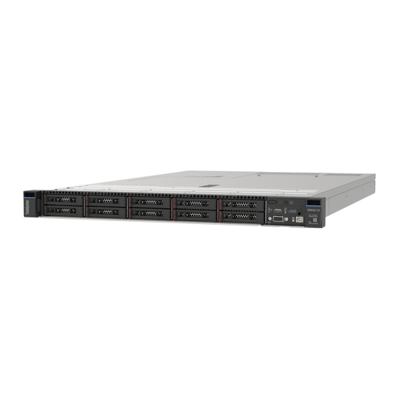
- Page 1 ThinkSystem SR630 V3 System Configuration Guide Machine Types: 7D72, 7D73, 7D74...
- Page 2 Before using this information and the product it supports, be sure to read and understand the safety information and the safety instructions, which are available at: https://pubs.lenovo.com/safety_documentation/ In addition, be sure that you are familiar with the terms and conditions of the Lenovo warranty for your server, which can be found at: http://datacentersupport.lenovo.com/warrantylookup Second Edition (May 2023) ©...
-
Page 3: Table Of Contents
Safety inspection checklist ... iv Set the network connection for the Lenovo XClarity Controller .... - Page 4 ThinkSystem SR630 V3 System Configuration Guide...
-
Page 5: Safety
Vor der Installation dieses Produkts die Sicherheitshinweise lesen. Prima di installare questo prodotto, leggere le Informazioni sulla Sicurezza. Les sikkerhetsinformasjonen (Safety Information) før du installerer dette produktet. Antes de instalar este produto, leia as Informações sobre Segurança. © Copyright Lenovo 2023... -
Page 6: Safety Inspection Checklist
1 & IEC 60950-1, the standard for Safety of Electronic Equipment within the Field of Audio/Video, Information Technology and Communication Technology. Lenovo assumes that you are qualified in the servicing of equipment and trained in recognizing hazards energy levels in products. Access to the equipment is by the use of a tool, lock and key, or other means of security, and is controlled by the authority responsible for the location. - Page 7 Click Power ➙ Power Cables to see all line cords. • Make sure that the insulation is not frayed or worn. 3. Check for any obvious non-Lenovo alterations. Use good judgment as to the safety of any non-Lenovo alterations.
- Page 8 ThinkSystem SR630 V3 System Configuration Guide...
-
Page 9: Chapter 1. Introduction
The Lenovo XClarity Controller consolidates multiple management functions in a single chip on the server system board (system board assembly). Some of the features that are unique to the Lenovo XClarity Controller are enhanced performance, higher-resolution remote video, and expanded security options. -
Page 10: Tech Tips
The server provides a QR code on the system service label, which is on the cover of the server, that you can scan using a QR code reader and scanner with a mobile device to get quick access to the Lenovo Service Information website. -
Page 11: Security Advisories
Follow the on-screen instructions to choose the category for the problem that you are having. Security advisories In order to protect our customers and their data, Lenovo is committed to developing products and services that adhere to the highest security standards. When potential vulnerabilities are reported, it is the... -
Page 12: Technical Specifications
• Up to 60 cores per socket • Up to 4 UPI links at up to 16 GT/s • Thermal Design Power (TDP): up to 350 watts For a list of supported processors, see: https://serverproven.lenovo.com ThinkSystem SR630 V3 System Configuration Guide... -
Page 13: Memory
• Minimum memory: 16 GB • Maximum memory: 8 TB: 32 x 256 GB 3DS RDIMMs For a list of supported memory options, see https://serverproven.lenovo.com For technical rules for memory modules, see “Memory module installation order” in User Guide or Hardware Maintenance Guide. -
Page 14: Internal Drives
Graphics processing unit (GPU) Your server supports the following GPUs: • Half-length, single-wide: – NVIDIA ® – NVIDIA ® Note: For GPU supporting rules, see “Thermal rules” in User Guide or Hardware Maintenance Guide. ThinkSystem SR630 V3 System Configuration Guide... -
Page 15: Integrated Functions And I/O Connectors
• Lenovo XClarity Controller (XCC), which provides service processor control and monitoring functions, video controller, and remote keyboard, video, mouse, and remote drive capabilities. – The server supports Lenovo XClarity Controller 2 (XCC2). For additional information about Lenovo XClarity Controller 2 (XCC2), refer to https://sysmgt.lenovofiles.com/help/topic/lxcc_frontend/lxcc_overview.html... -
Page 16: Raid Adapter
• ThinkSystem QLogic 16Gb Enhanced Gen5 FC Single-port HBA • ThinkSystem QLogic 16Gb Enhanced Gen5 FC Dual-port HBA • ThinkSystem Emulex 16Gb Gen6 FC Single-port HBA • ThinkSystem Emulex 16Gb Gen6 FC Dual-port HBA ThinkSystem SR630 V3 System Configuration Guide... -
Page 17: System Fan
System fan System fan • Supported fan types: – Standard fan 4056 (21000 RPM) – Performance fan 4056 (28000 RPM) • Fan redundancy: N+1 redundancy, one redundant fan rotor – One processor: six hot-swap dual-rotor system fans (one redundant fan rotor) –... -
Page 18: Mechanical Specifications
• Without package: up to 20 kg (44.09 lb) Environmental specifications Summary of the environmental specifications of the server. Depending on the model, some features might not be available, or some specifications might not apply. ThinkSystem SR630 V3 System Configuration Guide... - Page 19 • “Acoustical noise emissions” on page 12 • “Ambient temperature management” on page 13 • “Environment” on page 14 Chapter 1 Introduction...
- Page 20 6.7 Bel 8.3 Bel 53 dBA 68 dBA rich Thirty two 64 GB RDIMMs Ten SAS hard disk drives RAID 940-16i SFF adapter Intel X710-T2L 10GBASE-T 2-port OCP adapter Two 1100-watt power supply units Notes: ThinkSystem SR630 V3 System Configuration Guide...
- Page 21 Lenovo recommends that you consult with qualified experts in this field to determine whether you are in compliance with the applicable regulations.
- Page 22 If Lenovo determines that the levels of particulates or gases in your environment have caused damage to the device, Lenovo may condition provision of repair or replacement of devices or parts on implementation of appropriate remedial measures to mitigate such environmental contamination.
-
Page 23: Management Options
Table 3. Limits for particulates and gases Contaminant Limits Reactive gases Severity level G1 as per ANSI/ISA 71.04-1985 • The copper reactivity level shall be less than 200 Angstroms per month (Å/month ≈ 0.0035 μg/ -hour weight gain). • The silver reactivity level shall be less than 200 Angstroms per month (Å/month ≈ 0.0035 μg/ -hour weight gain). - Page 24 Suitable both for single-server or multi-server management contexts. Interface • OneCLI: CLI application Lenovo XClarity Essentials • Bootable Media Creator: CLI application, GUI application toolset • UpdateXpress: GUI application Usage and downloads http://sysmgt.lenovofiles.com/help/topic/xclarity_essentials/overview.html ThinkSystem SR630 V3 System Configuration Guide...
- Page 25 Important: Lenovo XClarity Provisioning Manager (LXPM) supported version varies by product. All versions of Lenovo XClarity Provisioning Manager are referred to as Lenovo XClarity Provisioning Manager and LXPM in this document, unless specified otherwise. To see the LXPM version supported by your server, go to https:// sysmgt.lenovofiles.com/help/topic/lxpm_frontend/lxpm_product_page.html...
- Page 26 1. Most options can be updated through the Lenovo tools. Some options, such as GPU firmware or Omni- Path firmware require the use of supplier tools. 2. The server UEFI settings for option ROM must be set to Auto or UEFI to update firmware using Lenovo XClarity Administrator, Lenovo XClarity Essentials, or Lenovo XClarity Controller.
-
Page 27: Chapter 2. Server Components
Server model with four 2.5-inch drive bays Table 4. Components on the front of the server Callout Callout Drive status LED Drive activity LED Diagnostics panel USB 3.2 Gen 1 (5Gbps) connector External LCD connector XClarity Controller USB connector © Copyright Lenovo 2023... - Page 28 External LCD connector XClarity Controller USB connector VGA connector (optional) Rack latch (right) Pull-out information tab Drive bays (8) Rack latch (left) Note: For more information about each component, see “Front components overview” on page ThinkSystem SR630 V3 System Configuration Guide...
- Page 29 Server model with ten 2.5-inch drive bays Table 6. Components on the front of the server Callout Callout Drive status LED Drive activity LED Diagnostics panel USB 3.2 Gen 1 (5Gbps) connector External LCD connector XClarity Controller USB connector VGA connector (optional) Rack latch (right) Pull-out information tab Drive bays (10)
- Page 30 XClarity Controller USB connector VGA connector (optional) Rack latch (right) Pull-out information tab M.2 cage Drive bays (16) Rack latch (left) Note: For more information about each component, see “Front components overview” on page ThinkSystem SR630 V3 System Configuration Guide...
- Page 31 Server model with four 3.5-inch drive bays Table 9. Components on the front of the server Callout Callout Rack latch (left) VGA connector (optional) External LCD connector XClarity Controller USB connector and USB 3.2 Gen 1 (5Gbps) connector Diagnostics panel Rack latch (right) Pull-out information tab Drive bays (4)
- Page 32 Rack latch (right) Pull-out information tab Drive fillers (4) Note: For more information about each component, see “Front components overview” on page Server model with eight 2.5-inch drive bays (with LCD diagnostics panel assembly) ThinkSystem SR630 V3 System Configuration Guide...
- Page 33 Table 12. Components on the front of the server Callout Callout Drive status LED Drive activity LED LCD diagnostics panel assembly LCD diagnostics panel USB 3.2 Gen 1 (5Gbps) connector External LCD connector XClarity Controller USB connector VGA connector (optional) Pull-out information tab Rack latch (right) Drive bays (8)
-
Page 34: Rear View
Pull-out information tab The Lenovo XClarity Controller network access label is attached on the pull-out information tab. The default Lenovo XClarity Controller hostname and the IPv6 Link Local Address (LLA) are provided on the tab. - Page 35 • “Server model with two 2.5-inch hot-swap rear drive bays and one PCIe slot” on page 28 • “Server model with two 7mm hot-swap rear drive bays and two PCIe slots” on page 29 • “Server model with two 7mm hot-swap rear drive bays and one PCIe slot” on page 29 Server model with three PCIe slots The following illustration shows the rear view of server model with three PCIe slots.
- Page 36 USB 3.2 Gen 1 (5Gbps) connectors (3 DCIs) XClarity Controller network connector Ethernet connectors on OCP module (optional, two or four connectors may be available) Note: For more information about each component, see “Rear components overview” on page ThinkSystem SR630 V3 System Configuration Guide...
- Page 37 Server model with two 7mm hot-swap rear drive bays and two PCIe slots The following illustration shows the rear view of the server model with two 7mm hot-swap rear drive bays and two PCIe slots. Depending on the model, your server might look slightly different from the illustration below. Table 18.
- Page 38 The hot-swap redundant power supply helps you avoid significant interruption to the operation of the system when a power supply fails. You can purchase a power supply option from Lenovo and install the power supply to provide power redundancy without turning off the server.
-
Page 39: Top View
VGA connector The VGA connectors on the front and rear of the server can be used to attach a high-performance monitor, a direct-drive monitor, or other devices that use a VGA connector. XClarity Controller network connector The XClarity Controller network connector can be used to attach an Ethernet cable to manage the baseboard management controller (BMC). - Page 40 For details, see “Rear view” on page 2. The illustration shows the location of certain parts. Some parts may not be supported at the same time within certain configuration(s). ThinkSystem SR630 V3 System Configuration Guide...
-
Page 41: Front I/O Module
Top view of a server with the liquid assisted cooling module installed The illustration below singles out the Liquid Assisted Cooling Module (LACM) from other components in the chassis. The parts contained depend on the configuration of the server. Figure 8. Top view of the LACM Table 21. - Page 42 • 8 x 2.5'' front drive bays • 10 x 2.5'' front drive bays • 16 EDSFF front drive bays Figure 9. FIO module type 1 • 10 x 2.5'' front drive bays Figure 10. FIO module type 2 ThinkSystem SR630 V3 System Configuration Guide...
-
Page 43: System-Board-Assembly Layout
FIO modules For server models with • 4 x 3.5'' front drive bays Figure 11. FIO module type 3 + external LCD cable • 8 x 2.5'' front drive bays • 16 EDSFF front drive bays Figure 12. FIO module type 4 + integrated diagnostics panel System-board-assembly layout The illustrations in this section provide information about the layout, connectors and switches that are... -
Page 44: System-Board-Assembly Connectors
For more information about the LEDs that are available on the system board assembly, see “System-board- assembly LEDs” in User Guide or Hardware Maintenance Guide. System-board-assembly connectors The following illustrations show the internal connectors on the system board assembly. ThinkSystem SR630 V3 System Configuration Guide... - Page 45 Figure 14. System-board-assembly connectors Table 22. System-board-assembly connectors NMI button Rear backplane sideband connector Rear USB connector 1 M.2/7mm backplane signal connector VGA connector CMOS battery socket Rear USB connector 2 Pump 1 connector Leak detection connector Management NIC connector MicroSD card socket Riser 1 slot Serial port connector...
-
Page 46: System-Board-Assembly Switches
• “Installation Guidelines”, “Handling static sensitive devices”, and “Power off the server ” in User Guide or Hardware Maintenance Guide. 2. Any system-board switch or jumper block that is not shown in the illustrations in this document are reserved. ThinkSystem SR630 V3 System Configuration Guide... - Page 47 Figure 15. System-board-assembly switches “Switch 2 (SW2)” on page 39 “Switch 7 (SW7)” on page 39 “Switch 6 (SW6)” on page 40 SW2 switch block The following table describes the functions of the SW2 switch block on the system board assembly. Table 23.
-
Page 48: System Leds And Diagnostics Display
For more information, refer to “Troubleshooting by system LEDs and diagnostics display” on page Troubleshooting by system LEDs and diagnostics display See the following section for information on available system LEDs and diagnostics display. ThinkSystem SR630 V3 System Configuration Guide... - Page 49 External diagnostics handset The external LCD diagnostics handset is an external device that is connected to the server with a cable, and it allows quick access to system information such as errors, system status, firmware, network, and health information. Note: The external diagnostics handset is an optional part that needs to be purchased separately. Location of the external diagnostics handset Location Callouts...
- Page 50 Option flow diagram The external diagnostics handset displays various system information. Navigate through the options with the scroll keys. Depending on the model, the options and entries on the LCD display might be different. ThinkSystem SR630 V3 System Configuration Guide...
- Page 51 Full menu list Following is the list of available options. Switch between an option and the subordinate information entries with the select button, and switch among options or information entries with the scroll buttons. Depending on the model, the options and entries on the LCD display might be different. Home Menu (System Status Dashboard) Chapter 2 Server components...
- Page 52 • Possible sources of the error CPU 1 Status: Configuration Error System VPD Information Sub Menu Example Machine Type: xxxx • Machine type and serial number Serial Num: xxxxxx • Universal Unique ID (UUID) Universal Unique ID: xxxxxxxxxxxxxxxxxxxxxxxxxxxx ThinkSystem SR630 V3 System Configuration Guide...
- Page 53 System Firmware Sub Menu Example XCC Primary XCC Primary (Active) • Firmware level (status) Build: DVI399T • Build ID Version: 4.07 • Version number Date: 2020-04-07 • Release date XCC Backup XCC Backup (Active) • Firmware level (status) Build: D8BT05I •...
- Page 54 • Generate/Download FFDC Service Data Integrated diagnostics panel The integrated diagnostics panel is attached to the front of the server, while it allows quick access to system information such as errors, system status, firmware, network, and health information. ThinkSystem SR630 V3 System Configuration Guide...
- Page 55 Location of the integrated diagnostics panel The integrated diagnostics panel is attached to the front of the server. Location The handle with which the panel can be pulled out from the server. Notes: Callout • The panel can be pushed in or pulled out regardless of the system power status. •...
- Page 56 Depending on the model, the options and entries on the LCD display might be different. Home Menu (System Status Dashboard) ThinkSystem SR630 V3 System Configuration Guide...
- Page 57 Home Menu Example System name System status Active alert quantity Temperature Power consumption Checkpoint code Active Alerts Sub Menu Example Home screen: Active error quantity Note: The “Active Alerts” menu displays only the quantity 1 Active Alerts of active errors. If no errors occur, the “Active Alerts” menu will not be available during navigation.
- Page 58 • Static IPv6 IP IPv4 Network Mask: • Current IPv6 Gateway x.x.x.x • IPv6 DNS IPv4 Default Gateway: Note: Only the MAC address that is currently in use is x.x.x.x displayed (extension or shared). ThinkSystem SR630 V3 System Configuration Guide...
- Page 59 System Environmental Information Sub Menu Example Ambient Temp: 24 C Exhaust Temp: 30 C • Ambient temperature CPU1 Temp: 50 C • Exhaust temperature PSU1: Vin= 213 w • CPU temperature Inlet= 26 C • PSU status FAN1 Front: 21000 RPM •...
- Page 60 Each time you press the system ID button, the state of both the system ID LEDs changes. The LEDs can be changed to on, blinking, or off. You can also use the Lenovo XClarity Controller or a remote management program to change the state of the system ID LEDs to assist in visually locating the server among other servers.
- Page 61 Description Action Amber An error has been detected on the server. • Check the Lenovo XClarity Controller Causes might include but are not limited to event log and the system event log to the following errors: determine the exact cause of the error.
- Page 62 LEDs on the Firmware and RoT Security Module The following illustrations show the light-emitting diodes (LEDs) on the ThinkSystem V3 Firmware and Root of Trust Security Module (Firmware and RoT Security Module). ThinkSystem SR630 V3 System Configuration Guide...
- Page 63 Figure 19. LEDs on the Firmware and RoT Security Module AP0 LED (Green) AP1 LED (Green) Fatal Error LED (Amber) Table 26. LEDs description FPGA Fatal heart- heart- beat beat Error note note Scenario Actions RoT security module fatal Replace the Firmware and firmware failure RoT Security Module.
- Page 64 System error LED (yellow) System ID LED (blue) XCC heartbeat LED (green) PCH heartbeat LED (green) FPGA heartbeat LED (green) System status LED (green) DIMM error LEDs (amber) Figure 20. LEDs on the system board assembly ThinkSystem SR630 V3 System Configuration Guide...
- Page 65 1. Re-plug the power cord. 2. Check and ensure that the system I/O board and the Firmware and RoT Security Module are installed correctly. (Trained technicians only) Reinstall them if needed. 3. If the problem remains, contact Lenovo Support. Chapter 2 Server components...
- Page 66 3. (Trained technicians only) If the problem remains, capture FFDC log, and replace the processor board. 4. If the problem still remains, contact Lenovo Support. DIMM error LEDs (amber) Description When a memory module error LED is lit, it indicates that the corresponding memory module has failed.
- Page 67 Rear LEDs This topic provides an overview of the LEDs on the rear of the server. Rear LEDs of the server The following illustration shows the LEDs on the rear view of server model with two PCIe slots and a two-bay 7mm drive cage.
- Page 68 • Green: The server is on and the power supply unit is working normally. Zero-output mode can be disabled via Setup utility or Lenovo XClarity Controller web interface. If you disable zero-output mode, both power supplies will be in the active state.
- Page 69 No action required. Blinking green Abnormal status detected. 1. Check for green coolant leakage around the radiator, liquid pipes and pumps. 2. If coolant leakage found, turn off the power and remove the LACM. 3. Contact Lenovo Support. Chapter 2 Server components...
- Page 70 ThinkSystem SR630 V3 System Configuration Guide...
-
Page 71: Chapter 3. Parts List
2. Click Parts. 3. Enter the serial number to view a listing of parts for your server. It is highly recommended that you check the power summary data for your server using Lenovo Capacity Planner before purchasing any new parts. - Page 72 Tier 1 CRU at your request with no service agreement, you will be charged for the installation. • Tier 2 customer replaceable unit (CRU): You may install a Tier 2 CRU yourself or request Lenovo to install it, at no additional charge, under the type of warranty service that is designated for your server.
- Page 73 Table 27. Parts list (continued) Index Description Tier 1 CRU Tier 2 CRU Consuma- ble and Structural part Integrated diagnostics panel assembly √ Integrated diagnostics panel √ M.2 cage √ Front I/O module with diagnostics panel (4) √ External LCD cable √...
-
Page 74: Power Cords
• For units intended to be operated at 115 volts: Use a UL-listed and CSA-certified cord set consisting of a minimum 18 AWG, Type SVT or SJT, three-conductor cord, a maximum of 15 feet in length and a parallel blade, grounding-type attachment plug rated 15 amperes, 125 volts. ThinkSystem SR630 V3 System Configuration Guide... - Page 75 • For units intended to be operated at 230 volts (U.S. use): Use a UL-listed and CSA-certified cord set consisting of a minimum 18 AWG, Type SVT or SJT, three-conductor cord, a maximum of 15 feet in length and a tandem blade, grounding-type attachment plug rated 15 amperes, 250 volts. •...
- Page 76 ThinkSystem SR630 V3 System Configuration Guide...
-
Page 77: Chapter 4. Unboxing And Setup
They might be required to receive warranty service. Identify the server and access the Lenovo XClarity Controller This section contains instruction on how to identify your server and where to find the Lenovo XClarity Controller access information. - Page 78 Figure 26. Location of the ID label Lenovo XClarity Controller network access label In addition, the Lenovo XClarity Controller network access label is attached to the pull-out information tab in the front of the chassis, with MAC address accessible with a pull.
-
Page 79: Server Setup Checklist
Service Label and QR code In addition, the system Service Label is located on the surface of the top cover, providing a quick response (QR) code for mobile access to service information. You can scan the QR code with a mobile device using a QR code reader application and get quick access to the Service Information web page. - Page 80 • You can press the power button. • The server can restart automatically after a power interruption. • The server can respond to remote power-on requests sent to the Lenovo XClarity Controller. Note: You can access the management processor interface to configure the system without powering on the server.
-
Page 81: Chapter 5. System Configuration
The following methods are available to set the network connection for the Lenovo XClarity Controller if you are not using DHCP: • If a monitor is attached to the server, you can use Lenovo XClarity Provisioning Manager to set the network connection. -
Page 82: Set Front Usb Port For Lenovo Xclarity Controller
ID button. To connect using the Lenovo XClarity Administrator Mobile app: 1. Connect the USB cable of your mobile device to the Lenovo XClarity Controller USB connector on the server. 2. On your mobile device, enable USB tethering. -
Page 83: Update The Firmware
Windows Server, Red Hat Enterprise Linux (RHEL) and SUSE Linux Enterprise Server (SLES) operating system distributions. Machine-type-specific firmware-only Static Bundles (Service Packs) are also available. Firmware updating tools See the following table to determine the best Lenovo tool to use for installing and setting up the firmware: Chapter 5 System configuration... - Page 84 Selected I/ √ √ Lenovo XClarity band O devices Integrator (LXCI) for VMware vCenter Off-Target In-band All I/O √ √ √ Lenovo XClarity devices Integrator (LXCI) for Out-of- Microsoft Windows band Admin Center On-Target Off-Target ThinkSystem SR630 V3 System Configuration Guide...
- Page 85 • Lenovo XClarity Controller If you need to install a specific update, you can use the Lenovo XClarity Controller interface for a specific server. Notes: – To perform an in-band update through Windows or Linux, the operating system driver must be installed and the Ethernet-over-USB (sometimes called LAN over USB) interface must be enabled.
-
Page 86: Configure The Firmware
Several options are available to install and set up the firmware for the server. Important: Lenovo does not recommend setting option ROMs to Legacy, but you can conduct this setting if necessary. Note that this setting prevents UEFI drivers for the slot devices from loading, which may cause negative side effects to Lenovo software, such as LXCA, OneCLI, and XCC. -
Page 87: Enable Software Guard Extensions (Sgx)
In addition, you can choose to make the text-based interface the default interface that is displayed when you start LXPM. To do this, go to Lenovo XClarity Provisioning Manager ➙ UEFI Setup ➙ System Settings ➙ <F1>Start Control ➙ Text Setup. To start the server with Graphic User Interface, select Auto or Tool Suite. -
Page 88: Raid Configuration
OS logical drives or volumes. An introduction to RAID is available at the following Lenovo Press website: https://lenovopress.lenovo.com/lp0578-lenovo-raid-introduction Detailed information about RAID management tools and resources is available at the following Lenovo Press website: https://lenovopress.lenovo.com/lp0579-lenovo-raid-management-tools-and-resources Notes: •... -
Page 89: Back Up The Server Configuration
• Multi-server Available tools: – Lenovo XClarity Administrator http://sysmgt.lenovofiles.com/help/topic/com.lenovo.lxca.doc/compute_node_image_deployment.html – Lenovo XClarity Essentials OneCLI http://sysmgt.lenovofiles.com/help/topic/toolsctr_cli_lenovo/onecli_r_uxspi_proxy_tool.html – Lenovo XClarity Integrator deployment pack for SCCM (for Windows operating system only) https://sysmgt.lenovofiles.com/help/topic/com.lenovo.lxci_deploypack_sccm.doc/dpsccm_c_endtoend_ deploy_scenario.html • Single-server Available tools: – Lenovo XClarity Provisioning Manager “OS Installation” section in the LXPM documentation compatible with your server at https:// sysmgt.lenovofiles.com/help/topic/lxpm_frontend/lxpm_product_page.html... - Page 90 • Management processor You can back up the management processor configuration through the Lenovo XClarity Controller interface. For details about backing up the management processor configuration, see: “Backing up the BMC configuration” section in the XCC documentation compatible with your server at https://sysmgt.lenovofiles.com/help/topic/lxcc_frontend/lxcc_overview.html...
-
Page 91: Appendix A. Getting Help And Technical Assistance
Appendix A. Getting help and technical assistance If you need help, service, or technical assistance or just want more information about Lenovo products, you will find a wide variety of sources available from Lenovo to assist you. On the World Wide Web, up-to-date information about Lenovo systems, optional devices, services, and support are available at: http://datacentersupport.lenovo.com... -
Page 92: Collecting Service Data
Collecting service data To clearly identify the root cause of a server issue or at the request of Lenovo Support, you might need collect service data that can be used for further analysis. Service data includes information such as event logs and hardware inventory. -
Page 93: Contacting Support
Support when certain serviceable events occur in Lenovo XClarity Administrator and the managed endpoints. You can choose to send diagnostic files to Lenovo Support using Call Home or to another service provider using SFTP. You can also manually collect diagnostic files, open a problem record, and send diagnostic files to the Lenovo Support. - Page 94 ThinkSystem SR630 V3 System Configuration Guide...
-
Page 95: Appendix B. Documents And Supports
– Hardware Maintenance Guide : Installing hardware components, cable routing, and troubleshooting. • Messages and Codes Reference – XClarity Controller, LXPM, and uEFI events • UEFI Manual – UEFI setting introduction Support websites This section provides driver and firmware downloads and support resources. © Copyright Lenovo 2023... - Page 96 ThinkSystem SR630 V3 System Configuration Guide...
-
Page 97: Appendix C. Notices
Lenovo representative for information on the products and services currently available in your area. Any reference to a Lenovo product, program, or service is not intended to state or imply that only that Lenovo product, program, or service may be used. Any functionally equivalent product, program, or service that does not infringe any Lenovo intellectual property right may be used instead. -
Page 98: Trademarks
(TBW). A device that has exceeded this limit might fail to respond to system-generated commands or might be incapable of being written to. Lenovo is not responsible for replacement of a device that has exceeded its maximum guaranteed number of program/erase cycles, as documented in the Official Published Specifications for the device. -
Page 99: Taiwan Region Bsmi Rohs Declaration
Taiwan Region BSMI RoHS declaration Taiwan Region import and export contact information Contacts are available for Taiwan Region import and export information. Appendix C. Notices... - Page 100 ThinkSystem SR630 V3 System Configuration Guide...
Need help?
Do you have a question about the ThinkSystem SR630 V3 and is the answer not in the manual?
Questions and answers