Table of Contents
Advertisement
Quick Links
Advertisement
Table of Contents

Related Manuals for Lenovo ThinkSystem SR635


Summary of Contents for Lenovo ThinkSystem SR635
- Page 1 ThinkSystem SR635 Maintenance Manual Machine Types: 7Y98 and 7Y99...
- Page 2 Before using this information and the product it supports, be sure to read and understand the safety information and the safety instructions, which are available at: http://thinksystem.lenovofiles.com/help/topic/safety_documentation/pdf_files.html In addition, ensure that you are familiar with the terms and conditions of the Lenovo warranty for your server, which can be found at: http://datacentersupport.lenovo.com/warrantylookup Eighth Edition (June 2021) ©...
-
Page 3: Table Of Contents
Technical rules for power supply ..Backplane replacement... . 131 Technical rules for system fans ..© Copyright Lenovo 2019, 2021... - Page 4 Fan board replacement ... . 189 Taiwan import and export contact information . . . 229 Remove the fan board ..189 ThinkSystem SR635 Maintenance Manual...
- Page 5 Index ....231 © Copyright Lenovo 2019, 2021...
- Page 6 ThinkSystem SR635 Maintenance Manual...
-
Page 7: Safety
Vor der Installation dieses Produkts die Sicherheitshinweise lesen. Prima di installare questo prodotto, leggere le Informazioni sulla Sicurezza. Les sikkerhetsinformasjonen (Safety Information) før du installerer dette produktet. Antes de instalar este produto, leia as Informações sobre Segurança. © Copyright Lenovo 2019, 2021... -
Page 8: Safety Inspection Checklist
1 & IEC 60950-1, the standard for Safety of Electronic Equipment within the Field of Audio/Video, Information Technology and Communication Technology. Lenovo assumes you are qualified in the servicing of equipment and trained in recognizing hazards energy levels in products. Access to the equipment is by the use of a tool, lock and key, or other means of security, and is controlled by the authority responsible for the location. - Page 9 Click the Power tab to see all line cords. • Make sure that the insulation is not frayed or worn. 3. Check for any obvious non-Lenovo alterations. Use good judgment as to the safety of any non-Lenovo alterations. 4. Check inside the server for any obvious unsafe conditions, such as metal filings, contamination, water or other liquid, or signs of fire or smoke damage.
- Page 10 ThinkSystem SR635 Maintenance Manual viii...
-
Page 11: Chapter 1. Introduction
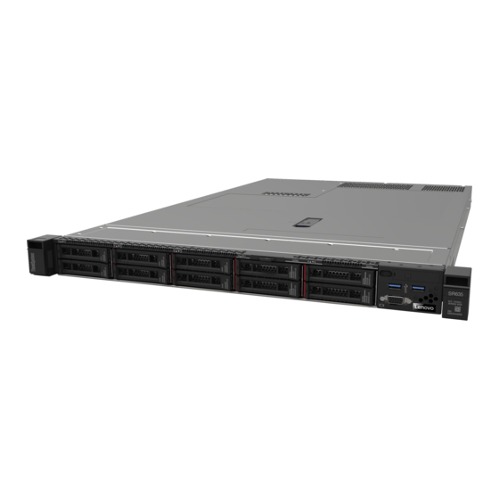
Chapter 1. Introduction The ThinkSystem SR635 server is a 1U rack server designed for performance and expansion for various IT workloads. With the modular design, the server is flexible to be customized for maximum storage capacity or high storage density with selectable input/output options and tiered system management. - Page 12 Figure 2. QR code ThinkSystem SR635 Maintenance Manual...
-
Page 13: Specifications
– TruDDR4 2933, quad-rank, 128 GB 3DS RDIMM Note: The operating speed and total memory capacity depend on the processor model and UEFI settings. For a list of supported memory, see the Lenovo ServerProven Web site: https:// static.lenovo.com/us/en/serverproven/index.shtml Internal drives •... - Page 14 Seven dual-rotor hot-swap fans (including one redundant fan rotor) Power supplies One or two hot-swap power supplies for redundancy support: • 550-watt ac 80 PLUS Platinum • 750-watt ac 80 PLUS Platinum • 750-watt ac 80 PLUS Titanium • 1100-watt ac 80 PLUS Platinum ThinkSystem SR635 Maintenance Manual...
- Page 15 Further, compliance with such government regulations depends on a variety of additional factors, including the duration of employees' exposure and whether employees wear hearing protection. Lenovo recommends that you consult with qualified experts in this field to determine whether you are in compliance with the applicable regulations.
- Page 16 – ASHRAE Class A2: 8%–80%, maximum dew point: 21°C (70°F) – ASHRAE Class A3: 8%–85%, maximum dew point: 24°C (75°F) – ASHRAE Class A4: 8%–90%, maximum dew point: 24°C (75°F) – Shipment or storage: 8%–90% • Particulate contamination ThinkSystem SR635 Maintenance Manual...
-
Page 17: Particulate Contamination
If Lenovo determines that the levels of particulates or gases in your environment have caused damage to the device, Lenovo may condition provision of repair or replacement of devices or parts on implementation of appropriate remedial measures to mitigate such environmental contamination. -
Page 18: Firmware Updates
You can use the tools listed here to update the most current firmware for your server and the devices that are installed in the server. Note: Lenovo typically releases firmware in bundles called UpdateXpress System Packs (UXSPs). To ensure that all of the firmware updates are compatible, you should update all firmware at the same time. If you are updating firmware for both the BMC and UEFI, update the firmware for BMC first. - Page 19 Machine-type-specific firmware-only UXSPs are also available. See the following table to determine the best Lenovo tool to use for installing and setting up the firmware: Note: The server UEFI settings for option ROM must be set to UEFI to update the firmware using Lenovo XClarity Essentials.
-
Page 20: Tech Tips
Tech Tips Lenovo continually updates the support Web site with the latest tips and techniques that you can use to solve issues that you might have with your server. These Tech Tips (also called retain tips or service bulletins) provide procedures to work around issues related to the operation of your server. -
Page 21: Security Advisories
Security advisories Lenovo is committed to developing products and services that adhere to the highest security standards in order to protect our customers and their data. When potential vulnerabilities are reported, it is the responsibility of the Lenovo Product Security Incident Response Team (PSIRT) to investigate and provide information to our customers so they may put mitigation plans in place as we work toward providing solutions. - Page 22 ThinkSystem SR635 Maintenance Manual...
-
Page 23: Chapter 2. Server Components
Figure 4. Front view of server model without a backplane (for four 3.5-inch drive bays) Figure 5. Front view of server model with eight 2.5-inch drive bays Figure 6. Front view of server model without a backplane (for ten 2.5-inch drive bays) © Copyright Lenovo 2019, 2021... - Page 24 The number of the installed drives in your server varies by model. When you install drives, follow the order of the drive bay numbers. The EMI integrity and cooling of the server are protected by having all drive bays occupied. The vacant drive bays must be occupied by drive fillers. Drive status LED ThinkSystem SR635 Maintenance Manual...
-
Page 25: Operator Information Panel
Drive activity LED Each hot-swap drive has two LEDs. Drive LED Status Description Drive status LED (right) Solid yellow The drive has an error. Blinking yellow (blinking slowly, about one The drive is being rebuilt. flash per second) Blinking yellow (blinking rapidly, about four The RAID adapter is locating the drive. -
Page 26: Rear View
The following illustration shows the rear view of server model with three PCIe slots. Depending on the model, your server might look slightly different from the illustration below. Figure 9. Rear view of server model with three PCIe slots ThinkSystem SR635 Maintenance Manual... - Page 27 Table 6. Components on the rear of the server PCIe slot 1 on riser 1 assembly PCIe slot 2 on riser 2 assembly PCIe slot 3 on riser 2 assembly Power supply 1 NMI button Power supply 2 (optional) Serial port USB 3.2 Gen 1 (5 Gbps) connectors VGA connector RJ45 BMC management network connector...
- Page 28 Rear view of server model with one PCIe slot The following illustration shows the rear view of the server model with one PCIe slot. Depending on the model, your server might look slightly different from the illustration below. ThinkSystem SR635 Maintenance Manual...
- Page 29 The hot-swap redundant power supplies help you avoid significant interruption to the operation of the system when a power supply fails. You can purchase a power supply option from Lenovo and install the power supply to provide power redundancy without turning off the server.
-
Page 30: Rear View Leds
Ethernet link LED Ethernet activity LED Power input LED Power output LED Power supply error LED System ID LED System error LED Ethernet link LED Ethernet activity LED The BMC network connector has two status LEDs. ThinkSystem SR635 Maintenance Manual... -
Page 31: System Board Components
Ethernet status LED Color Status Description Ethernet link LED Green Network link is established. None Network link is disconnected. Ethernet activity LED Green Blinking Network link is connected and active. None The server is disconnected from a LAN. 3 4 5 Power supply LEDs Each hot-swap power supply has three status LEDs. - Page 32 Riser 1 slot Front panel connector DIMM 1-16 error LEDs PCIe connector 6 PCIe connector 5 Front USB connector Fan board sideband connector (connect to PCIe connector 8 PCIe connector 4 Fan 7 connector PCIe connector 7 ThinkSystem SR635 Maintenance Manual...
- Page 33 Fan board sideband connector (connect to Fan 6 connector CPU power connector (connect to Fan 5 connector PCIe connector 3 PCIe connector 2 Fan 4 connector Fan 3 connector Fan 2 connector Fan 1 connector Fan board power connector (connect to Fan 1-7 error LEDs System power connector 2 (connect to PCIe connector 1...
-
Page 34: System Board Leds
Table 12. LEDs on the system board Callout Callout BMC heart beat LED System ID LED System error LED DIMM error LEDs (16) Fan error LEDs (7) BMC heart beat LED The BMC heart beat LED helps you identify the BMC status. ThinkSystem SR635 Maintenance Manual... - Page 35 Status Color Description Green The BMC is not alive. Blinking Green The BMC is alive. None The BMC is not alive. System ID LED The blue system ID LED helps you to visually locate the server. A system ID LED is also located on the front of the server.
-
Page 36: System Board Jumpers
Do not open your server or attempt any repair before reading and understanding the following information: – http://thinksystem.lenovofiles.com/help/topic/safety_documentation/pdf_files.html – “Handling static-sensitive devices” on page 82 • Any system-board switch or jumper block that is not shown in the illustrations in this document are reserved. Figure 17. System board jumpers ThinkSystem SR635 Maintenance Manual... -
Page 37: Internal Cable Routing
Table 13. Jumper description Jumper name Jumper number Jumper setting TPM physical • Pins 1 and 2: The jumper is in default setting. presence jumper • Pins 2 and 3: TPM physical presence is asserted. • Pins 1 and 2: The jumper is in default setting. Clear CMOS jumper •... -
Page 38: Power/Sideband Cable Routing
PIB sideband connector on the board system board System power connector 2 on the System power connector 2 on the PIB board system board Sideband connector on the fan board Fan sideband connector on the system board ThinkSystem SR635 Maintenance Manual... - Page 39 Figure 19. 2.5-inch chaiss-2 From Cable Front backplane power connector on Front backplane power connector on the front backplane the system board System power connector 1 on the System power connector 1 on the PIB board system board Power connector on the rear Rear backplane power connector on backplane the system board...
-
Page 40: Server Model With Four 3.5-Inch Sas/Sata
Fan sideband connector on the system board Server model with four 3.5-inch SAS/SATA drives Use this section to understand the connectors on the backplane and internal cable routing for server model with four 3.5-inch SAS/SATA drives. ThinkSystem SR635 Maintenance Manual... - Page 41 Figure 21. Connectors on the backplane for four 3.5-inch SAS/SATA drives SAS connector Power connector For power cable connection, see “Power/Sideband cable routing” on page 28. Refer to the following cable routing for different configurations: • “Four 3.5-inch SATA drives” on page 32 •...
- Page 42 Note: When the SAS/SATA backplanes are connected to PCIe connectors on the system board, only SATA drives are supported. No SAS drives are supported. Cable From SAS signal cable for front SAS connector on the front PCIe connector 7 on the system backplane backplane board ThinkSystem SR635 Maintenance Manual...
- Page 43 Four 3.5-inch SAS/SATA drives and one 8i RAID adapter Figure 23. Cable routing for server model with four 3.5-inch SAS/SATA drives and one 8i RAID adapter Note: RAID adapter can be installed in PCIe slot 1 or internal riser assembly. Cable From SAS signal cable for front...
- Page 44 Figure 24. Cable routing for server model with four 3.5-inch SATA drives and rear SAS/SATA drive assembly Cable From SAS signal cable for front SAS connector on the front PCIe connector 6 on the system backplane backplane board ThinkSystem SR635 Maintenance Manual...
- Page 45 Four 3.5-inch SAS/SATA drives, rear SAS/SATA drive assembly and one 8i RAID adapter Note: The cable routing illustration is based on the scenario that the rear hot-swap drive cage is installed. Depending on the model, the rear hot-swap drive cage might not be available on your server. Figure 25.
- Page 46 SAS signal cable for front SAS connector on the front PCIe connector 7 on the system backplane backplane board NVMe signal cable for rear NVMe connectors on the rear PCIe connector 1 on the system backplane backplane board ThinkSystem SR635 Maintenance Manual...
- Page 47 Four 3.5-inch SAS/SATA drives, rear NVMe drive assembly and one 8i RAID adapter Note: The cable routing illustration is based on the scenario that the rear hot-swap drive cage is installed. Depending on the model, the rear hot-swap drive cage might not be available on your server. Figure 27.
- Page 48 NVMe signal cable for internal PCIe connector 9 on the system backplane backplane board NVMe signal cable for internal NVMe 0–1 connector on the internal PCIe connector 7 and PCIe backplane backplane connector 8 on the system board ThinkSystem SR635 Maintenance Manual...
-
Page 49: Server Model With Eight 2.5-Inch Sas/Sata
Four 3.5-inch SAS/SATA drives, middle drive cage and one 8i RAID adapter Figure 29. Cable routing for server model with four 3.5-inch SAS/SATA drives, middle drive cage and one 8i RAID adapter Cable From SAS signal cable for front SAS connector on the front C0 connector on the RAID adapter backplane backplane... - Page 50 Figure 31. Cable routing for server model with eight 2.5-inch SATA drives From Cable SAS signal cable for front SAS 0 and SAS 1 connectors on PCIe connector 6 on the system board backplane the front backplane ThinkSystem SR635 Maintenance Manual...
- Page 51 Eight 2.5-inch SAS/SATA drives and one 8i RAID adapter Figure 32. Cable routing for server model with eight 2.5-inch SAS/SATA drives and one 8i RAID adapter Note: RAID adapter can be installed in PCIe slot 1 or internal riser assembly. Cable From SAS signal cable for front...
- Page 52 SAS 0 and SAS 1 connectors on PCIe connector 6 on the system board backplane the front backplane SAS signal cable for rear SAS connector on the rear PCIe connector 7 on the system board backplane backplane ThinkSystem SR635 Maintenance Manual...
- Page 53 Eight 2.5-inch SAS/SATA drives, rear SAS/SATA drive assembly and two 8i RAID adapters Figure 34. Cable routing for server model with eight 2.5-inch SAS/SATA drives, rear SAS/SATA drive assembly and two 8i RAID adapters From Cable SAS signal cable for front SAS 0 and SAS 1 connectors on C0 and C1 connectors on the RAID adapter backplane...
- Page 54 SAS 0 and SAS 1 connectors on C0 and C1 connectors on the RAID adapter backplane the front backplane SAS signal cable for rear SAS connector on the rear C2 connector on the RAID adapter backplane backplane ThinkSystem SR635 Maintenance Manual...
- Page 55 Eight 2.5-inch SATA drives and rear NVMe drive assembly Notes: • When the SAS/SATA backplanes are connected to PCIe connectors on the system board, only SATA drives are supported. No SAS drives are supported. • The cable routing illustration is based on the scenario that the rear hot-swap drive cage is installed. Depending on the model, the rear hot-swap drive cage might not be available on your server.
- Page 56 SAS 0 and SAS 1 connectors on C0 and C1 connectors on the RAID adapter backplane the front backplane NVMe signal cable for rear NVMe connectors on the rear PCIe connector 1 on the system board backplane backplane ThinkSystem SR635 Maintenance Manual...
-
Page 57: Server Model With Six 2.5-Inch Sas/Sata Drives And Four 2.5-Inch Nvme Drives
Server model with six 2.5-inch SAS/SATA drives and four 2.5-inch NVMe drives Use this section to understand the connectors on the backplane and the internal cable routing for server model with six 2.5-inch SAS/SATA drives and four 2.5-inch NVMe drives. Figure 38. - Page 58 SAS 2 connector on the front PCIe connector 7 on the system backplane backplane board SAS signal cable for front SAS 0 and SAS 1 connectors on the PCIe connector 6 on the system backplane front backplane board ThinkSystem SR635 Maintenance Manual...
- Page 59 Six 2.5-inch SAS/SATA drives, four 2.5-inch NVMe drives and one 16i RAID adapter Figure 40. Cable routing for server model with six 2.5-inch SAS/SATA drives, four 2.5-inch NVMe drives and one 16i RAID adapter Note: RAID adapter can be installed in PCIe slot 1 or internal riser assembly. Cable From NVMe signal cable for front...
- Page 60 SAS signal cable for front SAS 2 connector on the front PCIe connector 7 on the system backplane backplane board SAS signal cable for rear SAS connector on the rear backplane PCIe connector 8 on the system backplane board ThinkSystem SR635 Maintenance Manual...
- Page 61 Six 2.5-inch SAS/SATA drives, four 2.5-inch NVMe drives, rear SAS/SATA drive assembly and one 16i RAID adapter Note: The cable routing illustration is based on the scenario that the rear hot-swap drive cage is installed. Depending on the model, the rear hot-swap drive cage might not be available on your server. Figure 42.
- Page 62 SAS signal cable for front SAS 2 connector on the front PCIe connector 7 on the system backplane backplane board NVMe connectors on the rear NVMe signal cable for rear PCIe connector 3 on the system backplane backplane board ThinkSystem SR635 Maintenance Manual...
- Page 63 Six 2.5-inch SAS/SATA drives, four 2.5-inch NVMe drives, rear NVMe drive assembly and one 16i RAID adapter Note: The cable routing illustration is based on the scenario that the rear hot-swap drive cage is installed. Depending on the model, the rear hot-swap drive cage might not be available on your server. Figure 44.
-
Page 64: Server Model With Ten 2.5-Inch Sas/Sata/ Nvme Drives
• “Ten 2.5-inch SAS/SATA/NVMe drives, middle NVMe drive assembly and one 16i RAID adapter” on page Ten 2.5-inch SATA/NVMe drives Note: When the SAS/SATA backplanes are connected to PCIe connectors on the system board, only SATA drives are supported. No SAS drives are supported. ThinkSystem SR635 Maintenance Manual... - Page 65 Figure 46. Cable routing for server model with ten 2.5-inch SATA/NVMe drives Cable From NVMe signal cable for front NVMe 0–1 connector on the front PCIe connector 1 on the system backplane backplane board NVMe signal cable for front NVMe 2–3 connector on the front PCIe connector 2 on the system backplane backplane...
- Page 66 PCIe slot 1 SAS signal cable for front SAS/SATA 8–9 connector on the front C2 connector on RAID adapter in backplane backplane PCIe slot 1 Ten 2.5-inch SATA/NVMe drives and rear SAS/SATA drive assembly Notes: ThinkSystem SR635 Maintenance Manual...
- Page 67 • When the SAS/SATA backplanes are connected to PCIe connectors on the system board, only SATA drives are supported. No SAS drives are supported. • The cable routing illustration is based on the scenario that the rear hot-swap drive cage is installed. Depending on the model, the rear hot-swap drive cage might not be available fon your server.
- Page 68 NVMe signal cable for front NVMe 2–3 connector on the front PCIe connector 2 on the system backplane backplane board NVMe signal cable for front NVMe 4–5 connector on the front PCIe connector 3 on the system backplane backplane board ThinkSystem SR635 Maintenance Manual...
- Page 69 Cable From NVMe signal cable for front NVMe 6–7 connector on the front PCIe connector 4 on the system backplane backplane board NVMe signal cable for front NVMe 8–9 connector on the front PCIe connector 5 on the system backplane backplane board SAS signal cable for front...
- Page 70 Depending on the model, the rear hot-swap drive cage and middle NVMe drive assembly might not be available on your server. • The following two illustrations are for the same one configuration. ThinkSystem SR635 Maintenance Manual...
- Page 71 Figure 51. Cable routing for server model with ten 2.5-inch SAS/SATA/NVMe drives, rear SAS/SATA drive assembly, middle NVMe drive assembly and one 16i RAID adapter-1 Cable From NVMe signal cable for front NVMe 0–1 connector on the front PCIe connector 1 on the system backplane backplane board...
- Page 72 • Ten 2.5-inch NVMe drives and rear NVMe drive assembly: Connect Cable , Cable , and Cable • Ten 2.5-inch NVMe drives and middle NVMe drive assembly: Connect Cable , Cable , Cable , and Cable ThinkSystem SR635 Maintenance Manual...
- Page 73 Figure 53. Cable routing for server model with ten 2.5-inch NVMe drives, rear NVMe drive assembly and middle NVMe drive assembly From Cable NVMe 0–1, NVMe 2–3, and NVMe 4– NVMe signal cable for front PCIe connector 1, PCIe connector 2, backplane 5 connectors on the front backplane and PCIe connector 3 on the system...
- Page 74 NVMe 2–3 connector on the middle PCIe connector 9 on the system backplane backplane board NVMe signal cable for rear NVMe 0 and NVMe 1 connectors on PCIe connector 6 on the system the rear backplane backplane board ThinkSystem SR635 Maintenance Manual...
- Page 75 Figure 55. Cable routing for server model with ten 2.5-inch SAS/SATA/NVMe drives, rear SAS/SATA drive assembly, middle NVMe drive assembly and one 16i RAID adapter-2 Cable From SAS signal cable for front SAS/SATA 0–3 and SAS/SATA 4–7 C0 and C1 connectors on RAID backplane connectors on the front backplane adapter in PCIe slot 1...
- Page 76 NVMe 0–1 connector on the middle NVMe signal cable for middle PCIe connector 7 on the system backplane backplane board NVMe 2–3 connector on the middle NVMe signal cable for middle PCIe connector 9 on the system backplane backplane board ThinkSystem SR635 Maintenance Manual...
-
Page 77: M.2 Module Cable Routing
Figure 57. Cable routing for server model with ten 2.5-inch SAS/SATA/NVMe drives, middle NVMe drive assembly and one 16i RAID adapter-2 Cable From SAS signal cable for front SAS/SATA 0–3 and SAS/SATA 4–7 C0 and C1 connectors on RAID backplane connectors on the front backplane adapter in PCIe slot 1 SAS signal cable for front... - Page 78 Figure 58. Cable routing for server model with M.2 module Cable From M.2 sideband connectors on the M.2 M.2 sideband connector on the module system board Power connector on the M.2 module PCIe connector 8 on the system board ThinkSystem SR635 Maintenance Manual...
-
Page 79: Super Capacitor Cable Routing
Super capacitor cable routing Use the section to understand the cable routing for the super capacitor. Cable routing for server model with two super capacitors Note: For server model with 3.5-inch drive bays, it supports up to two RAID super capacitor modules. Figure 59. -
Page 80: Vga/Usb/Front Panel Connector
Use the section to understand the cable routing for the VGA/USB/Front panel connector on the left rack latch. Note: The VGA connector is available on some models. The following is the cable routing for server model with four 3.5-inch drive bays. ThinkSystem SR635 Maintenance Manual... - Page 81 Figure 61. VGA/USB/Front panel connector cable routing for server model with four 3.5-inch drive bays Cable USB cable from the front of server Front USB connector on the system board Front panel cable from the front of server Front Panel connector on the system board VGA cable from the front of server Front VGA connector on the system board The following is the cable routing for server model with eight/ten 2.5-inch drive bays.
-
Page 82: Intrusion Switch Cable Routing
Front Panel connector on the system board VGA cable from the front of server Front VGA connector on the system board Intrusion switch cable routing Use the section to understand the cable routing for the intrusion switch. ThinkSystem SR635 Maintenance Manual... - Page 83 Figure 63. Cable routing for server model with intrusion switch Cable Intrusion switch cable from the riser bracket Intrusion switch connector on the system board Chapter 2 Server components...
-
Page 84: Parts List
Use the parts list to identify each of the components that are available for your server. For more information about ordering the parts shown in Figure 64 “Server components” on page 74: http://datacentersupport.lenovo.com/us/en/products/servers/thinksystem/sr635/7y98/parts Note: Depending on the model, your server might look slightly different from the illustration. Figure 64. Server components ThinkSystem SR635 Maintenance Manual... - Page 85 Tier 1 CRU at your request with no service agreement, you will be charged for the installation. • Tier 2 customer replaceable unit (CRU): You may install a Tier 2 CRU yourself or request Lenovo to install it, at no additional charge, under the type of warranty service that is designated for your server.
- Page 86 Backplane, ten 2.5-inch AnyBay hot- √ swap drives Middle backplane, four 2.5-inch hot- √ swap drives Memory module √ Heat sink √ Internal drive cage, four 2.5-inch hot- √ swap drives Rear wall bracket √ CMOS battery √ Processor √ ThinkSystem SR635 Maintenance Manual...
-
Page 87: Power Cords
Several power cords are available, depending on the country and region where the server is installed. To view the power cords that are available for the server: 1. Go to: http://dcsc.lenovo.com/#/ 2. Click Preconfigured Model or Configure to order. 3. Enter the machine type and model for your server to display the configurator page. - Page 88 ThinkSystem SR635 Maintenance Manual...
-
Page 89: Chapter 3. Hardware Replacement Procedures
• When you install a new server, download and apply the latest firmware. This will help ensure that any known issues are addressed, and that your server is ready to work with optimal performance. Go to ThinkSystem SR635 Drivers and Software to download firmware updates for your server. -
Page 90: Safety Inspection Checklist
1 & IEC 60950-1, the standard for Safety of Electronic Equipment within the Field of Audio/Video, Information Technology and Communication Technology. Lenovo assumes you are qualified in the servicing of equipment and trained in recognizing hazards energy levels in products. Access to the equipment is by the use of a tool, lock and key, or other means of security, and is controlled by the authority responsible for the location. -
Page 91: System Reliability Guidelines
Click the Power tab to see all line cords. • Make sure that the insulation is not frayed or worn. 3. Check for any obvious non-Lenovo alterations. Use good judgment as to the safety of any non-Lenovo alterations. 4. Check inside the server for any obvious unsafe conditions, such as metal filings, contamination, water or other liquid, or signs of fire or smoke damage. -
Page 92: Handling Static-Sensitive Devices
• 10/25 GbE Ethernet adapters with AOC are supported in PCIe slot 1 or 3 when the ambient temperature is less than 30°C. • 100/200 GbE Ethernet adapters are supported in PCIe slot 1 or 3 when the ambient temperature is less than 30°C. • Fibre channel card is not supported in PCIe slot 2. ThinkSystem SR635 Maintenance Manual... -
Page 93: Technical Rules For Power Supply
Technical rules for power supply The following table lists the technical rules between processor TDP and GPU adapters for different configurations with different types of power supply. • For 750-watt power supply: Configuration Processor TDP 4 x 3.5-inch front drive bays 120/155/180/200 watts 120 watts 8 x 2.5-inch front drive bays... - Page 94 Supported configuration Processor TDP 4 x 3.5-inch front drive bays 120/155/180/200/225/240/280 watts 4 x 3.5-inch front drive bays + middle NVMe drives 120/155/180/200/225/240/280 watts 4 x 3.5-inch front drive bays + rear SAS/SATA/NVMe 120/155 watts drives ThinkSystem SR635 Maintenance Manual...
-
Page 95: Technical Rules For System Fans
Supported configuration Processor TDP 8 x 2.5-inch front drive bays 120/155/180/200/225/240/280 watts 8 x 2.5-inch front drive bays + rear SAS/SATA/NVMe 120/155 watts drives 6 x 2.5-inch front drive bays + 4 x 2.5-inch AnyBay front 120/155/180/200/225/240/280 watts drive bays 6 x 2.5-inch front drive bays + 4 x 2.5-inch AnyBay front 120/155 watts drive bays + rear SAS/SATA/NVMe drives... - Page 96 • PCIe slot priority to install the GPU: PCIe slot 1, PCIe slot 3, PCIe slot 2. • High-performance fan must be selected. • Internal drive assembly and rear drive cage are not supported. • PCIe SSD adapter is not supported. ThinkSystem SR635 Maintenance Manual...
-
Page 97: Technical Rules For Drives
– NVMe SSD For a list of supported drives, see: https://static.lenovo.com/us/en/serverproven/index.shtml • The drive bays are numbered to indicate the installation order (starting from number “0”). Follow the installation order when you install a drive. See “Front view” on page 13. -
Page 98: Technical Rules For Hba/Raid Adapters
Notes: The following adapters require a full-height bracket and must be installed in a full-height slot: • ThinkSystem Broadcom 57454 10/25GbE SFP28 4-port PCIe Ethernet Adapter • ThinkSystem Broadcom 57454 10/25GbE SFP28 4-port PCIe Ethernet Adapter_Refresh (V2) ThinkSystem SR635 Maintenance Manual... -
Page 99: Top Cover Replacement
Top cover replacement Use this information to remove and install the top cover. Remove the top cover Use this information to remove the top cover. “Read the “Power off “ATTENTION: installation the server for Static Sensitive Device Guidelines” on this task” on Ground package before opening”... -
Page 100: Install The Top Cover
3. If you are installing a new top cover, attach the service label to the new top cover first if necessary. Note: A new top cover comes without a service label attached. If you need a service label, order it together with the new top cover. The service label is free of charge. ThinkSystem SR635 Maintenance Manual... -
Page 101: Air Baffle Replacement
To install the top cover, complete the following steps: Watch the procedure. A video of the installation and removal process is available: • YouTube: https://www.youtube.com/playlist?list=PLYV5R7hVcs-DTDY1lmpIPpJVOzo7dKq14 • Youku: http://list.youku.com/albumlist/show/id_52222446.html Figure 66. Top cover installation Step 1. Ensure that the cover latch is in the open position. Lower the top cover onto the chassis until both sides of the top cover engage with the guides on both sides of the chassis. -
Page 102: Remove The Air Baffle
Watch the procedure. A video of the installation and removal process is available: • YouTube: https://www.youtube.com/playlist?list=PLYV5R7hVcs-DTDY1lmpIPpJVOzo7dKq14 • Youku: http://list.youku.com/albumlist/show/id_52222446.html Note: The air baffle you want to remove might be different from the following illustrations, but the removal method is the same. ThinkSystem SR635 Maintenance Manual... -
Page 103: Install The Air Baffle
Figure 67. Air baffle removal Step 1. Grasp the air baffle and carefully lift it out of the server. Attention: For proper cooling and airflow, install the air baffle before you power on the server. Operating the server with the air baffle removed might damage server components. Install the air baffle Use this information to install the air baffle. -
Page 104: Rack Latches Replacement
1. If the server is installed with the security bezel, remove it first. See “Remove the security bezel” on page 2. Use a flat-blade screwdriver to remove the ID label plate on the right rack latch and place it in a safe place. ThinkSystem SR635 Maintenance Manual... - Page 105 Figure 69. ID label plate removal To remove the rack latches, complete the following steps: Watch the procedure. A video of the installation and removal process is available: • YouTube: https://www.youtube.com/playlist?list=PLYV5R7hVcs-DTDY1lmpIPpJVOzo7dKq14 • Youku: http://list.youku.com/albumlist/show/id_52222446.html Step 1. On each side of the server, remove the two screws that secure the rack latch. Chapter 3 Hardware replacement procedures...
- Page 106 Figure 70. Rack latch screws removal Step 2. On each side of the server, remove the rack latch from the chassis as shown. Figure 71. Rack latch removal ThinkSystem SR635 Maintenance Manual...
-
Page 107: Install The Rack Latches
If you are instructed to return the old rack latches, follow all packaging instructions and use any packaging materials that are provided. Install the rack latches Use this information to install the rack latches. “Read the installation Guidelines” on page 79 To install the rack latches, complete the following steps: Watch the procedure. - Page 108 After installing the rack latches: 1. Install the ID label plate to the right rack latch as shown. Figure 74. ID label plate installation 2. Complete the parts replacement. See “Complete the parts replacement” on page 203. ThinkSystem SR635 Maintenance Manual...
-
Page 109: Security Bezel Replacement
Security bezel replacement Use this information to remove and install the security bezel. Remove the security bezel Use this information to remove the security bezel. “Read the installation Guidelines” on page 79 To remove the security bezel, complete the following steps: Watch the procedure. -
Page 110: Install The Security Bezel
Watch the procedure. A video of the installation and removal process is available: • YouTube: https://www.youtube.com/playlist?list=PLYV5R7hVcs-DTDY1lmpIPpJVOzo7dKq14 • Youku: http://list.youku.com/albumlist/show/id_52222446.html Step 1. If the key is held inside the security bezel, remove it out of the security bezel. ThinkSystem SR635 Maintenance Manual... - Page 111 Figure 77. Key removal Step 2. Insert the tab on the security bezel into the slot on the right side of the chassis. Then, press and hold the blue release latch and pivot the security bezel inward until it clicks into place. Figure 78.
-
Page 112: System Fan Replacement
79 on page 82 S033 CAUTION: Hazardous energy present. Voltages with hazardous energy might cause heating when shorted with metal, which might result in spattered metal, burns, or both. S017 CAUTION: Hazardous moving fan blades nearby. ThinkSystem SR635 Maintenance Manual... -
Page 113: Install A System Fan
Before removing a system fan, remove the top cover. See “Remove the top cover” on page 89. To remove a system fan, complete the following step: Watch the procedure. A video of the installation and removal process is available: • YouTube: https://www.youtube.com/playlist?list=PLYV5R7hVcs-DTDY1lmpIPpJVOzo7dKq14 •... - Page 114 See “Technical rules for system fans” on page 85 before you install system fans. To install a system fan, complete the following steps: Watch the procedure. A video of the installation and removal process is available: • YouTube: https://www.youtube.com/playlist?list=PLYV5R7hVcs-DTDY1lmpIPpJVOzo7dKq14 • Youku: http://list.youku.com/albumlist/show/id_52222446.html ThinkSystem SR635 Maintenance Manual...
-
Page 115: Memory Module Replacement
Figure 81. System fan installation Step 1. Align the two holes in the system fan with the two pins on the chassis. Step 2. Press the system fan down until it is seated correctly in the slot. Ensure that the fan connector is installed correctly to the connector on the system board. - Page 116 Attention: To avoid breaking the retaining clips or damaging the memory module slots, handle the clips gently. Step 2. Grasp the memory module at both ends and carefully lift it out of the slot. After removing a memory module: ThinkSystem SR635 Maintenance Manual...
-
Page 117: Memory Module Installation Rules
– TruDDR4 2933, quad-rank, 128 GB 3DS RDIMM For a list of supported memory options, see: https://static.lenovo.com/us/en/serverproven/index.shtml Follow the below rules when you install or replace a memory module: • Memory modules in your server must be the same type. - Page 118 Table 15. DIMM installation order Unified Memory UMC2 UMC3 UMC1 UMC0 UMC6 UMC7 UMC5 UMC4 Controller (UMC) Channel (CH) CH slot DIMM number 1 DIMM 2 DIMMs 3 DIMMs 4 DIMMs 5 DIMMs 6 DIMMs 7 DIMMs ThinkSystem SR635 Maintenance Manual...
-
Page 119: Install A Memory Module
Table 15. DIMM installation order (continued) 8 DIMMs 9 DIMMs 10 DIMMs 11 DIMMs 12 DIMMs 13 DIMMs 14 DIMMs 15 DIMMs 16 DIMMs Install a memory module Use this information to install a memory module. “Read the “Power off “ATTENTION: installation the server for... -
Page 120: Hot-Swap Drive Replacement
Use this information to remove and install a hot-swap drive. You can remove or install a hot-swap drive without turning off the server, which helps you avoid significant interruption to the operation of the system. Notes: ThinkSystem SR635 Maintenance Manual... -
Page 121: Remove A Hot-Swap Drive
• The term “hot-swap drive” refers to all the supported types of hot-swap hard disk drives, hot-swap solid- state drives, and hot-swap NVMe drives. • Use any documentation that comes with the drive and follow those instructions in addition to the instructions in this topic. -
Page 122: Install A Hot-Swap Drive
2. Touch the static-protective package that contains the new drive to any unpainted surface on the outside of the server. Then, take the new drive out of the package and place it on a static-protective surface. 3. See “Technical rules for drives” on page 87 before you install the hot-swap drive. ThinkSystem SR635 Maintenance Manual... -
Page 123: Ocp 3.0 Ethernet Adapter Replacement
Continue to install additional hot-swap drives if necessary. After installing all hot-swap drives: 1. Reinstall the security bezel. See “Install the security bezel” on page 100. 2. Use the Lenovo XClarity Provisioning Manager Lite to configure the RAID if necessary. For more information, see: https://sysmgt.lenovofiles.com/help/topic/lxpml_v2/Introduction.html OCP 3.0 Ethernet adapter replacement... -
Page 124: Install The Ocp 3.0 Ethernet Adapter
Ethernet adapter out of the package and place it on a static-protective surface. To install the OCP 3.0 Ethernet adapter, complete the following steps: Watch the procedure. A video of the installation and removal process is available: • YouTube: https://www.youtube.com/playlist?list=PLYV5R7hVcs-DTDY1lmpIPpJVOzo7dKq14 ThinkSystem SR635 Maintenance Manual... -
Page 125: Internal Riser Assembly Replacement
• Youku: http://list.youku.com/albumlist/show/id_52222446.html Step 1. Attach the OCP 3.0 Ethernet adapter label that comes with this option on the rear of the server. Figure 90. OCP 3.0 Ethernet adapter label installation Step 2. Push the OCP 3.0 Ethernet adapter as shown to insert it into the connector on the system board. Tighten the thumbscrew to secure the adapter. -
Page 126: Install The Internal Riser Assembly
“Power off “ATTENTION: installation the server for Static Sensitive Device Guidelines” on this task” on Ground package before opening” page 79 page 11 on page 82 To install the internal riser assembly, complete the following steps: ThinkSystem SR635 Maintenance Manual... -
Page 127: Riser Card Replacement
Watch the procedure. A video of the installation and removal process is available: • YouTube: https://www.youtube.com/playlist?list=PLYV5R7hVcs-DTDY1lmpIPpJVOzo7dKq14 • Youku: http://list.youku.com/albumlist/show/id_52222446.html Step 1. Install the internal riser assembly and install the super capacitor on the internal riser assembly. See “Install a super capacitor module on the M.2/riser support bracket” on page 168. Step 2. -
Page 128: Remove A Riser Card
Ground package before opening” page 79 page 11 on page 82 Before removing a riser card, remove the top cover. See “Remove the top cover” on page 89. To remove a riser card, complete the following steps: ThinkSystem SR635 Maintenance Manual... - Page 129 Note: The riser assembly you want to remove might be different from the following illustrations, but the removal method is the same. Watch the procedure. A video of the installation and removal process is available: • YouTube: https://www.youtube.com/playlist?list=PLYV5R7hVcs-DTDY1lmpIPpJVOzo7dKq14 • Youku: http://list.youku.com/albumlist/show/id_52222446.html Step 1.
-
Page 130: Install A Riser Card
Position the riser assembly on the chassis. Align the two pins on the bracket with the two holes in the chassis and align the riser card with the riser slot on the system board. Then, carefully press the riser assembly straight down into the slot until it is fully seated. ThinkSystem SR635 Maintenance Manual... -
Page 131: Pcie Adapter Replacement
Figure 100. Riser assembly installation According to the configuration, you may also need to install the rear wall bracket between the two riser assemblies. Figure 101. Rear wall bracket installation After installing the riser card, complete the parts replacement. See “Complete the parts replacement” on page 203. -
Page 132: Remove A Pcie Adapter
Step 1. Pivot the latch on the riser bracket to the open position. Step 2. Grasp the PCIe adapter by its edges and carefully pull it out of the PCIe adapter slot on the riser card. ThinkSystem SR635 Maintenance Manual... - Page 133 Figure 102. Riser 1 assembly (LP/FHFL) removal Chapter 3 Hardware replacement procedures...
- Page 134 Figure 103. Riser 2 assembly (LP+LP) removal Figure 104. Internal riser assembly (LP) removal If you are instructed to return the old PCIe adapter, follow all packaging instructions and use any packaging materials that are provided. ThinkSystem SR635 Maintenance Manual...
-
Page 135: Install A Pcie Adapter
Install a PCIe adapter Use this information to install a PCIe adapter. “Read the “Power off “ATTENTION: installation the server for Static Sensitive Device Guidelines” on this task” on Ground package before opening” page 79 page 11 on page 82 Before installing a PCIe adapter: 1. - Page 136 Figure 105. Riser 1 assembly (LP/FHFL) installation ThinkSystem SR635 Maintenance Manual...
- Page 137 Figure 106. Riser 2 assembly (LP+LP) installation Figure 107. Internal riser assembly (LP) installation Step 3. Connect cables to the PCIe adapter in the riser assembly. See “Internal cable routing” on page 27. After installing the PCIe adapter: 1. Reinstall the riser assembly. See “Install a riser card” on page 120. Chapter 3 Hardware replacement procedures...
-
Page 138: Intrusion Switch Replacement
For different types of supported riser bracket, see Figure 105 “Riser 1 assembly (LP/FHFL) installation” on page 126. Step 1. Slide the intrusion switch as shown to remove it from the riser bracket. ThinkSystem SR635 Maintenance Manual... -
Page 139: Install An Intrusion Switch
Figure 108. Intrusion switch removal If you are instructed to return the old intrusion switch, follow all packaging instructions and use any packaging materials that are provided. Install an intrusion switch Use this information to install an intrusion switch. “Read the “Power off “ATTENTION: installation... -
Page 140: Gpu Replacement
To remove a GPU adapter, complete the following steps: Watch the procedure. A video of the installation and removal process is available: • YouTube: https://www.youtube.com/playlist?list=PLYV5R7hVcs-DTDY1lmpIPpJVOzo7dKq14 • Youku: http://list.youku.com/albumlist/show/id_52222446.html Step 1. Disconnect the power cable from the GPU adapter. ThinkSystem SR635 Maintenance Manual... -
Page 141: Install A Gpu Adapter
Step 2. Remove the GPU adapter from the riser bracket. See “Remove a PCIe adapter” on page 122. If you are instructed to return the old GPU adapter, follow all packaging instructions and use any packaging materials that are provided. Install a GPU adapter Use this information to install a GPU adapter. -
Page 142: Install The Backplane For Four 3.5-Inch Hot
Use this information to install the backplane for four 3.5-inch hot-swap drives. “Read the “Power off “ATTENTION: installation the server for Static Sensitive Device Guidelines” on this task” on Ground package before opening” page 79 page 11 on page 82 Before installing the backplane: ThinkSystem SR635 Maintenance Manual... - Page 143 1. Touch the static-protective package that contains the new backplane to any unpainted surface on the outside of the server. Then, take the new backplane out of the package and place it on a static- protective surface. 2. Connect the cables to the backplane. See “Server model with four 3.5-inch SAS/SATA drives” on page To install the backplane, complete the following steps: Watch the procedure.
-
Page 144: Remove The Backplane For Eight 2.5-Inch Hot
If you are instructed to return the old backplane, follow all packaging instructions and use any packaging materials that are provided. Install the backplane for eight 2.5-inch hot-swap drives Use this information to install the backplane for eight 2.5-inch hot-swap drives. ThinkSystem SR635 Maintenance Manual... -
Page 145: Remove The Backplane For Ten 2.5-Inch Hot
“Read the “Power off “ATTENTION: installation the server for Static Sensitive Device Guidelines” on this task” on Ground package before opening” page 79 page 11 on page 82 Before installing the backplane: 1. Touch the static-protective package that contains the new backplane to any unpainted surface on the outside of the server. -
Page 146: Install The Backplane For Ten 2.5-Inch Hot
If you are instructed to return the old backplane, follow all packaging instructions and use any packaging materials that are provided. Install the backplane for ten 2.5-inch hot-swap drives Use this information to install the backplane for ten 2.5-inch hot-swap drives. ThinkSystem SR635 Maintenance Manual... - Page 147 “Read the “Power off “ATTENTION: installation the server for Static Sensitive Device Guidelines” on this task” on Ground package before opening” page 79 page 11 on page 82 Before installing the backplane: 1. Touch the static-protective package that contains the new backplane to any unpainted surface on the outside of the server.
-
Page 148: Remove The Rear Backplane
Carefully lift the rear backplane out of the rear hot-swap drive cage. Note: There are two types of rear backplanes. The rear backplane you want to install might be different from the following illustration, but the installation method is the same. ThinkSystem SR635 Maintenance Manual... -
Page 149: Install The Rear Backplane
Figure 117. Rear backplane removal If you are instructed to return the old rear backplane, follow all packaging instructions and use any packaging materials that are provided. Install the rear backplane Use this information to install the rear backplane. “Read the “Power off “ATTENTION: installation... - Page 150 Figure 118. Rear backplane installation Step 2. Connect the signal cable and the power cable on the rear backplane. Refer to “Internal cable routing” on page 27. Figure 119. NVMe rear backplane connectors Power connector NVMe signal connector ThinkSystem SR635 Maintenance Manual...
- Page 151 Figure 120. SAS/SATA rear backplane connectors SAS/SATA signal connector Power connector Step 3. Install the air baffle into the rear hot-swap drive cage as shown. Figure 121. Air baffle installation After installing the rear backplane: 1. Reinstall the drives or drive fillers into the rear hot-swap drive cage. See “Install a hot-swap drive” on page 112.
-
Page 152: Cmos Battery Replacement
The following tips describe information that you must consider when removing the CMOS battery. • Lenovo has designed this product with your safety in mind. The lithium CMOS battery must be handled correctly to avoid possible danger. If you replace the CMOS battery, you must adhere to the following instructions. -
Page 153: Install The Cmos Battery
CAUTION: The power-control button on the device and the power switch on the power supply do not turn off the electrical current supplied to the device. The device also might have more than one power cord. To remove all electrical current from the device, ensure that all power cords are disconnected from the power source. - Page 154 • Lenovo has designed this product with your safety in mind. The lithium battery must be handled correctly to avoid possible danger. If you install the CMOS battery, you must adhere to the following instructions. Note: In the U. S., call 1-800-IBM-4333 for information about battery disposal.
-
Page 155: Tpm Adapter Replacement
Figure 123. CMOS battery installation Step 1. Touch the static-protective package that contains the new CMOS battery to any unpainted surface on the outside of the server. Then, take the new CMOS battery out of the package. Step 2. Install the new CMOS battery. Ensure that the CMOS battery is seated in place. After installing the CMOS battery: 1. -
Page 156: Install The Tpm Adapter
Before installing the TPM adapter, touch the static-protective package that contains the new TPM adapter to any unpainted surface on the outside of the server. Then, take the new TPM adapter out of the package and place it on a static-protective surface. ThinkSystem SR635 Maintenance Manual... -
Page 157: Rear Hot-Swap Drive Cage Replacement
To install the TPM adapter, complete the following steps: Watch the procedure. A video of the installation and removal process is available: • YouTube: https://www.youtube.com/playlist?list=PLYV5R7hVcs-DTDY1lmpIPpJVOzo7dKq14 • Youku: http://list.youku.com/albumlist/show/id_52222446.html Step 1. Locate the TPM connector on the system board. Step 2. Insert the TPM adapter into the TPM connector on the system board. -
Page 158: Remove The Rear Hot-Swap Drive Cage
If you are instructed to return the old rear hot-swap drive cage, follow all packaging instructions and use any packaging materials that are provided. Install the rear hot-swap drive cage Use this information to install the rear hot-swap drive cage. ThinkSystem SR635 Maintenance Manual... - Page 159 “Read the “Power off “ATTENTION: installation the server for Static Sensitive Device Guidelines” on this task” on Ground package before opening” page 79 page 11 on page 82 Before installing the rear hot-swap drive cage, touch the static-protective package that contains the new rear hot-swap drive cage to any unpainted surface on the outside of the server.
- Page 160 Figure 128. Rear backplane installation Step 3. Connect the signal cable and the power cable on the rear backplane. Refer to “Internal cable routing” on page 27. Figure 129. NVMe rear backplane connectors Power connector NVMe signal connector ThinkSystem SR635 Maintenance Manual...
- Page 161 Figure 130. SAS/SATA rear backplane connectors SAS/SATA signal connector Power connector Step 4. Install the air baffle into the rear hot-swap drive cage as shown. Figure 131. Air baffle installation Step 5. Align the three pins on the rear hot-swap drive cage with the holes and slot in the chassis. Then, lower the rear hot-swap drive cage into the chassis until it is fully seated.
-
Page 162: Middle Drive Cage Replacement
1. Remove the top cover. See “Remove the top cover” on page 89. 2. Disconnect the cables from the backplane. To remove the middle drive cage, complete the following steps: Watch the procedure. A video of the installation and removal process is available: ThinkSystem SR635 Maintenance Manual... - Page 163 • YouTube: https://www.youtube.com/playlist?list=PLYV5R7hVcs-DTDY1lmpIPpJVOzo7dKq14 • Youku: http://list.youku.com/albumlist/show/id_52222446.html Step 1. Remove all the installed drives from the drive bays in the middle cage. To remove the drives, do the following: Hold and lift the two blue handles. Pull the hot-swap drives from the internal drive cage. See “Remove a hot-swap drive” on page 111.
- Page 164 Figure 134. Internal drive removal-2 Step 2. Loosen the thumbscrews that secure the middle drive cage. Figure 135. Middle drive cage removal-1 Step 3. Hold and lift the middle drive cage from the chassis as shown. ThinkSystem SR635 Maintenance Manual...
-
Page 165: Install The Middle Drive Cage
Figure 136. Middle drive cage removal-2 Step 4. Remove the internal backplane from the middle drive cage. Remove the screws that secure the internal backplane in the middle drive cage. Lift the internal backplane out of the middle drive cage. Figure 137. - Page 166 Align the two pins on the middle drive cage with the holes and slot in the chassis. Then, lower the middle drive assembly into the chassis and push forward the cage until it is fully seated. ThinkSystem SR635 Maintenance Manual...
- Page 167 Figure 139. Middle drive cage installation-1 Step 3. Tighten the thumbscrews to secure the middle drive cage. Chapter 3 Hardware replacement procedures...
- Page 168 Figure 140. Middle drive cage installation-2 Step 4. Hold and lift the two blue handles. Install the hot-swap drives in the middle drive cage. Figure 141. Internal hot-swap drive installation-1 Step 5. Press two blue handles and slide down the cage. ThinkSystem SR635 Maintenance Manual...
-
Page 169: M.2 Adapter And M.2 Drive Replacement
After installing all hot-swap drives: 1. Connect the cables to the middle drive cage. See “Internal cable routing” on page 27. 2. Use the Lenovo XClarity Provisioning Manager Lite to configure the RAID if necessary. For more information, see: https://sysmgt.lenovofiles.com/help/topic/lxpml_v2/Introduction.html 3. - Page 170 Rotate the M.2 drive away from the M.2 adapter. Pull the M.2 drive away from the connector at an angle of approximately 30 degrees. Step 2. Loosen the screw and remove the M.2 adapter from the bracket. ThinkSystem SR635 Maintenance Manual...
- Page 171 Figure 144. M.2 adapter removal Step 3. Remove the M.2 adapter bracket if necessary. Chapter 3 Hardware replacement procedures...
-
Page 172: Adjust The Retainer On The M.2 Adapter
Note: The M.2 adapter might be different from the following illustrations, but the adjustment method is the same. Watch the procedure. A video of the installation and removal process is available: • YouTube: https://www.youtube.com/playlist?list=PLYV5R7hVcs-DTDY1lmpIPpJVOzo7dKq14 • Youku: http://list.youku.com/albumlist/show/id_52222446.html ThinkSystem SR635 Maintenance Manual... -
Page 173: Install The M.2 Adapter And M.2 Drive
Figure 146. M.2 retainer adjustment Step 1. Press both sides of the retainers. Step 2. Move the retainer forward until it is in the large opening of the keyhole. Step 3. Take the retainer out of the keyhole. Step 4. Insert the retainer into the correct keyhole. - Page 174 See “Install a super capacitor module on the M.2/riser support bracket” on page 168. Step 2. Align the pins of the M.2 module bracket with the two holes on both sides of the M.2/riser support bracket, and then install the bracket on the super capacitor modules. ThinkSystem SR635 Maintenance Manual...
- Page 175 Figure 148. M.2 module bracket installation Step 3. Install the M.2 adapter into the bracket and tighten the screw. Chapter 3 Hardware replacement procedures...
- Page 176 Insert the M.2 drive at an angle of approximately 30 degrees into the connector. Rotate the M.2 drive down until the notch catches on the lip of the retainer Slide the retainer forward (toward the connector) to secure the M.2 drive into place. ThinkSystem SR635 Maintenance Manual...
-
Page 177: Raid Super Capacitor Module Replacement
1. Connect the cables of the M.2 adapter. See “M.2 module cable routing” on page 67. 2. Complete the parts replacement. See “Complete the parts replacement” on page 203. 3. Use the Lenovo XClarity Provisioning Manager Lite to configure the RAID. For more information, see: https://sysmgt.lenovofiles.com/help/topic/lxpml_v2/Introduction.html RAID super capacitor module replacement Use this information to remove and install a RAID super capacitor module. -
Page 178: Install A Super Capacitor Module On The M.2/Riser Support Bracket
• Youku: http://list.youku.com/albumlist/show/id_52222446.html Step 1. Open the retention clip on a holder, put a super capacitor module into the holder, and press it down to secure it into the holder. Figure 152. Super capacitor module installation ThinkSystem SR635 Maintenance Manual... -
Page 179: Remove The Raid Super Capacitor Module On
After installing the super capacitor module: 1. Connect the super capacitor module to an adapter with the extension cable that comes with the super capacitor module. See “Super capacitor cable routing” on page 69. 2. Complete the parts replacement. See “Complete the parts replacement” on page 203. Remove the RAID super capacitor module on the chassis Use this information to remove the RAID super capacitor module on the chassis. -
Page 180: Install The Raid Super Capacitor Module On
Watch the procedure. A video of the installation and removal process is available: • YouTube: https://www.youtube.com/playlist?list=PLYV5R7hVcs-DTDY1lmpIPpJVOzo7dKq14 • Youku: http://list.youku.com/albumlist/show/id_52222446.html Step 1. If the server comes with a tray that covers the place of the RAID super capacitor module on the chassis, remove it first. ThinkSystem SR635 Maintenance Manual... - Page 181 Figure 155. Tray removal Step 2. If the server does not have a RAID super capacitor module holder on the chassis, install one first. Chapter 3 Hardware replacement procedures...
-
Page 182: Front I/O Assembly Replacement
See “Super capacitor cable routing” on page 69. 2. Complete the parts replacement. See “Complete the parts replacement” on page 203. Front I/O assembly replacement Use this information to remove and install the front I/O assembly. ThinkSystem SR635 Maintenance Manual... -
Page 183: Remove The Front I/O Assembly
Remove the front I/O assembly Use this information to remove the front I/O assembly. “Read the “Power off “ATTENTION: installation the server for Static Sensitive Device Guidelines” on this task” on Ground package before opening” page 79 page 11 on page 82 Before removing the front I/O assembly: 1. -
Page 184: Hot-Swap Power Supply Replacement
2. Complete the parts replacement. See “Complete the parts replacement” on page 203. Hot-swap power supply replacement Use this information to remove and install a hot-swap power supply. Remove a hot-swap power supply Use this information to remove a hot-swap power supply. ThinkSystem SR635 Maintenance Manual... - Page 185 “Read the “ATTENTION: installation Static Sensitive Device Guidelines” on Ground package before opening” page 79 on page 82 S035 CAUTION: Never remove the cover on a power supply or any part that has this label attached. Hazardous voltage, current, and energy levels are present inside any component that has this label attached. There are no serviceable parts inside these components.
- Page 186 240 V dc input cannot support hot plugging power cord function. Before removing the power supply with dc input, please turn off server or disconnect dc power sources at the breaker panel or by turning off the power source. Then, remove the power cord. 在直流输入状态下,若电源供应器插座不支持热插拔功能,请务必不要对设备电源线进行热插拔。此操作可能 导致设备损坏及数据丢失。因错误执行热插拔导致的设备故障或损坏,不属于保修范围。 ThinkSystem SR635 Maintenance Manual...
- Page 187 NEVER CONNECT AND DISCONNECT THE POWER SUPPLY CABLE AND EQUIPMENT WHILE YOUR EQUIPMENT IS POWERED ON WITH DC SUPPLY (hot-plugging). Otherwise you may damage the equipment and result in data loss, the damages and losses result from incorrect operation of the equipment will not be covered by the manufacturers’...
- Page 188 Note: Slightly pull the power supply upwards when sliding the power supply out of the chassis, if you have installed one of the following CMA kits: • 1U CMA Upgrade Kit for Toolless Slide Rail • Toolless Slide Rail Kit with 1U CMA ThinkSystem SR635 Maintenance Manual...
-
Page 189: Install A Hot-Swap Power Supply
• Ensure that the devices that you are installing are supported. For a list of supported optional devices for the server, see https://static.lenovo.com/us/en/serverproven/index.shtml Notes: • Ensure that the two power supplies installed on the server have the same wattsage. - Page 190 The device also might have more than one power cord. To remove all electrical current from the device, ensure that all power cords are disconnected from the power source. S001 ThinkSystem SR635 Maintenance Manual...
- Page 191 DANGER Electrical current from power, telephone, and communication cables is hazardous. To avoid a shock hazard: • Do not connect or disconnect any cables or perform installation, maintenance, or reconfiguration of this product during an electrical storm. • Connect all power cords to a properly wired and grounded electrical outlet. •...
- Page 192 If the server is in a rack, adjust the CMA to gain access to the power supply bay. If you have installed the 1U CMA Upgrade Kit for Toolless Slide Rail or Toolless Slide Rail Kit with 1U CMA, do the following: ThinkSystem SR635 Maintenance Manual...
- Page 193 Figure 166. CMA adjustment Press down the stop bracket and rotate it to the open position. Rotate the CMA out of the way to gain access to the power supply bay. Step 2. Remove the power-supply filler. Figure 167. Hot-swap power supply filler removal Step 3.
-
Page 194: Heat Sink And Microprocessor Replacement
• It may take some time for the heat sink to cool down after the system has been powered down. • The heat sink is necessary to maintain proper thermal conditions for the processor. Do not power on the server with the heat sink removed. ThinkSystem SR635 Maintenance Manual... -
Page 195: Remove A Processor
Before removing the heat sink, • Remove the top cover. See “Remove the top cover” on page 89. • Remove the air baffle. See “Remove the air baffle” on page 92. • Remove any parts and disconnect any cables that might impede your access to the heat sink and processor. -
Page 196: Install A Processor
• Optional devices available for your system might have specific processor requirements. See “Technical rules” on page 82. To install a processor, complete the following steps: Watch the procedure. A video of the installation and removal process is available: • YouTube: https://www.youtube.com/playlist?list=PLYV5R7hVcs-DTDY1lmpIPpJVOzo7dKq14 • Youku: http://list.youku.com/albumlist/show/id_52222446.html ThinkSystem SR635 Maintenance Manual... - Page 197 Figure 171. Installing a processor Step 1. Slide the processor carrier into the rail frame. Step 2. Push the rail frame down until the blue latches lock into place. Step 3. Close the force frame. Step 4. Tighten the screws in the installation sequence shown on the force frame. After installing a processor, install the heat sink by referring to “Install a heat sink”...
-
Page 198: Install A Heat Sink
• If you use a new heat sink, the thermal grease is pre-applied to the heat sink. Remove the protective cover and install the heat sink. To install a heat sink, complete the following steps: Watch the procedure. A video of the installation and removal process is available: • YouTube: https://www.youtube.com/playlist?list=PLYV5R7hVcs-DTDY1lmpIPpJVOzo7dKq14 • Youku: http://list.youku.com/albumlist/show/id_52222446.html ThinkSystem SR635 Maintenance Manual... -
Page 199: Fan Board Replacement
Figure 173. Installing a heat sink Step 1. Orient the heat sink with the screw holes on the processor plate. The captive screws on the heat sink should align with the screw holes on the processor plate. Step 2. Tighten all the captive screws in the installation sequence shown on the heat-sink label. After installing a heat sink: 1. -
Page 200: Install The Fan Board
Then, take the new fan board out of the package and place it on a static-protective surface. To install the fan board, complete the following steps: Watch the procedure. A video of the installation and removal process is available: • YouTube: https://www.youtube.com/playlist?list=PLYV5R7hVcs-DTDY1lmpIPpJVOzo7dKq14 • Youku: http://list.youku.com/albumlist/show/id_52222446.html ThinkSystem SR635 Maintenance Manual... -
Page 201: Power Inverter Board (Pib) Board Replacement
Figure 175. Fan board installation Step 1. Gently hold and lower the fan board into the system board tray. Step 2. Install the five screws to secure the fan board. After installing the fan board: 1. Install the system fans. See “Install a system fan” on page 103. 2. -
Page 202: Install The Pib Board
Then, take the new PIB board out of the package and place it on a static-protective surface. To install the PIB board, complete the following steps: Watch the procedure. A video of the installation and removal process is available: • YouTube: https://www.youtube.com/playlist?list=PLYV5R7hVcs-DTDY1lmpIPpJVOzo7dKq14 • Youku: http://list.youku.com/albumlist/show/id_52222446.html ThinkSystem SR635 Maintenance Manual... -
Page 203: System Board Replacement
Figure 177. PIB board installation Step 1. Gently hold and lower the PIB board into the system board tray. Step 2. Install the five screws to secure the PIB board. After installing the PIB board: 1. Connect all the cables from the PIB board. See “Power/Sideband cable routing” on page 28. 2. - Page 204 Watch the procedure. A video of the installation and removal process is available: • YouTube: https://www.youtube.com/playlist?list=PLYV5R7hVcs-DTDY1lmpIPpJVOzo7dKq14 • Youku: http://list.youku.com/albumlist/show/id_52222446.html Note: Depending on the model, the blue lift handle on your system board might look slightly different from the illustration below. ThinkSystem SR635 Maintenance Manual...
-
Page 205: Install The System Board
Figure 178. System board removal Step 1. Lift the release pin and hold the lift handle at the same time and slide the system board toward the front of the server. Step 2. Lift the system board out of the chassis. If you are instructed to return the old system board, follow all packaging instructions and use any packaging materials that are provided. - Page 206 2. Install any of the following components that are removed from the system board. See the related topics in this chapter. See Chapter 3 “Hardware replacement procedures” on page 79 • Fan board • PIB board • System fans ThinkSystem SR635 Maintenance Manual...
-
Page 207: Update The Vital Product Data (Vpd)
• Lenovo XClarity Essentials OneCLI commands Using Lenovo XClarity Provisioning Manager Lite V2 Steps: 1. Start the server and press F11. The Lenovo XClarity Provisioning Manager Lite V2 interface is displayed by default. 2. Choose System Summary. The “System Summary” tab page is displayed. - Page 208 In this case, specify below BMC account information and IP address at the end of the OneCLI command: --bmc <bmc_user_id>:xcc_password@<bmc_external_IP> Notes: – <bmc_user_id> The BMC account name (1 of 12 accounts). The default value is USERID. – <bmc_password> The BMC account password (1 of 12 accounts). ThinkSystem SR635 Maintenance Manual...
-
Page 209: Configure Security Settings
Configure security settings Use this section to configure security settings after the system board is replaced. Outside Chinese Mainland Chinese Mainland Security setting features 7002 CPU 7003 CPU 7002 CPU 7003 CPU Physical presence Required Required Required Required assertion TPM policy setting & Required Required Required... - Page 210 Recommended tools Lenovo XClarity Essentials OneCLI commands Setting the policy Note: Please note that a Local IPMI user and password must be setup in Lenovo XClarity Controller for remote accessing to the target system. Steps: 1. Read TpmTcmPolicyLock to check whether the TPM_TCM_POLICY has been locked: OneCli.exe config show bmc.TpmTcmPolicyLock --override --bmc...
- Page 211 • Value 1 use string “NeitherTpmNorTcm”, which means TPM_PERM_DISABLED. • Value 2 use string “TpmOnly”, which means TPM_ALLOWED. • Value 4 use string “NationZTPM20Only”, which means NationZTPM20_ALLOWED. Locking the TPM policy Steps: 1. Read TpmTcmPolicyLock to check whether the TPM_TCM_POLICY has been locked: OneCli.exe config show bmc.TpmTcmPolicyLock --override --bmc <userid>:<password>@<ip_address>...
- Page 212 3. Once the TPM firmware version has been upgraded, it cannot be rolled back. Recommended tools: Lenovo XClarity Essentials OneCLI commands Using Lenovo XClarity Essentials OneCLI commands Use the following commands to toggle the TPM firmware version. TPM 1.2 (7.4.0.0) -> TPM 1.2 (7.4.0.1): OneCli.exe config set TrustedComputingGroup.DeviceOperation "Update to TPM 2.0 firmware version 7.4.0.1"...
-
Page 213: Complete The Parts Replacement
• Update the system firmware. See “Firmware updates” on page 8. • Use the Lenovo XClarity Provisioning Manager Lite to configure the RAID if you have installed or removed a hot-swap drive, a RAID adapter, or the M.2 adapter and M.2 drive. For more information, see: https://sysmgt.lenovofiles.com/help/topic/lxpml_v2/Introduction.html... - Page 214 ThinkSystem SR635 Maintenance Manual...
-
Page 215: Chapter 4. Problem Determination
To isolate a problem, you should typically begin with the event log of the application that is managing the server: • If you are managing the server from the Lenovo XClarity Administrator, begin with the Lenovo XClarity Administrator event log. -
Page 216: Light Path Diagnostics
If you are not sure about the cause of a problem and the power supplies are working correctly, complete the following steps to attempt to resolve the problem: 1. Power off the server. 2. Make sure that the server is cabled correctly. ThinkSystem SR635 Maintenance Manual... -
Page 217: Resolving Suspected Power Problems
• Any external devices, • Surge-suppressor device (on the server). • Printer, mouse, and non-Lenovo devices, • Each adapter. • Hard disk drives. • Memory modules until you reach the minimum configuration that is supported for the server. -
Page 218: Troubleshooting By Symptom
1. Check the event log of the application that is managing the server and follow the suggested actions to resolve any event codes. • If you are managing the server from the Lenovo XClarity Administrator, begin with the Lenovo XClarity Administrator event log. - Page 219 3. Check to validate that the embedded hypervisor https://static.lenovo.com/us/en/serverproven/index.shtml device is supported for the server. 4. Make sure that the embedded hypervisor device is listed in the list of available boot options. From the management controller user interface, click Server Configuration ➙ Boot Options.
-
Page 220: Memory Problems
3. Reseat the DIMMs, and then restart the server. 4. Run memory diagnostics. When you start a server and press F11, the Lenovo XClarity Provisioning Manager Lite V2 interface is displayed by default. You can perform memory diagnostics from this interface. -
Page 221: Hard Disk Drive Problems
Run the diagnostics tests for the hard disk drives. When you start a server and press F11, the Lenovo XClarity Provisioning Manager Lite V2 interface is displayed by default. You can perform hard disk drive diagnostics from this interface. From the Diagnostic page, click Run Diagnostic ➙... - Page 222 • Replace the affected backplane. 8. Run the diagnostics tests for the hard disk drives. When you start a server and press F11, the Lenovo XClarity Provisioning Manager Lite V2 interface is displayed by default. You can perform hard disk drive diagnostics from this interface.
-
Page 223: Monitor And Video Problems
To use the management controller remote presence function, remove the optional video adapter. 3. If the server is installed with the graphical adapters while turning on the server, the Lenovo logo displays on the screen after approximately 3 minutes. This is normal operation while the system loads. -
Page 224: Keyboard, Mouse, Or Usb-Device Problems
To prevent diskette drive read/write errors, make sure that the distance between the monitor and any external diskette drive is at least 76 mm (3 in.). b. Non-Lenovo monitor cables might cause unpredictable problems. 2. Reseat the monitor cable. -
Page 225: Optional-Device Problems
• “External USB device not recognized” on page 215 • “A Lenovo optional device that worked previously does not work now. ” on page 216 • “A Lenovo optional device that was just installed does not work” on page 216 •... -
Page 226: Serial-Device Problems
7. Ensure any adapter external connections are correct and that the connectors are not physically damaged. A Lenovo optional device that was just installed does not work 1. Make sure that: • The device is supported for the server (see https://static.lenovo.com/us/en/serverproven/index.shtml... -
Page 227: Intermittent Problems
• The device is compatible with the server. • The serial port is enabled and is assigned a unique address. • The device is connected to the correct connector. 2. Reseat the following components: a. Failing serial device. b. Serial cable. 3. -
Page 228: Power Problems
2. Generate a new license key and log in again. Observable problems Use this information to solve observable problems. • “The server immediately displays the POST Event Viewer when it is turned on” on page 219 ThinkSystem SR635 Maintenance Manual... - Page 229 You can view processor details from system setup. To determine if the processor is supported for the server, see https://static.lenovo.com/us/en/ serverproven/index.shtml 6. (Trained technician only) Make sure that the processor is seated correctly. 7. Replace the following components one at a time, in the order shown, and restart the server each time: a.
- Page 230 Complete the following steps until the problem is solved. 1. An unusual smell might be coming from newly installed equipment. 2. If the problem remains, contact Lenovo Support. Server seems to be running hot Complete the following steps until the problem is solved.
-
Page 231: Software Problems
3. Select Save. 4. Reboot the system and auto boot to operation system. Cracked parts or cracked chassis Contact Lenovo Support. Software problems Use this information to solve software problems. 1. To determine whether the problem is caused by the software, make sure that: •... - Page 232 ThinkSystem SR635 Maintenance Manual...
-
Page 233: Appendix A. Hardware Disassembling For Recycle
1. Remove the system board from the server (see “Remove the system board” on page 193). 2. Refer to local environmental, waste or disposal regulations to ensure compliance. Complete the following steps to disassemble the system board: © Copyright Lenovo 2019, 2021... - Page 234 • Four hexagon bolts on VGA and COM (RS232) connectors (with 5 mm wrench) Step 2. Separate the components from the system board. 1 2 3 4 5 6 7 After disassembling the system board, comply with local regulations when recycling. ThinkSystem SR635 Maintenance Manual...
-
Page 235: Appendix B. Getting Help And Technical Assistance
Gathering information needed to call Support If you believe that you require warranty service for your Lenovo product, the service technicians will be able to assist you more efficiently if you prepare before you call. You can also see http:// for more information about your product warranty. -
Page 236: Collecting Service Data
Collecting service data To clearly identify the root cause of a server issue or at the request of Lenovo Support, you might need collect service data that can be used for further analysis. Service data includes information such as event logs and hardware inventory. -
Page 237: Appendix C. Notices
Lenovo representative for information on the products and services currently available in your area. Any reference to a Lenovo product, program, or service is not intended to state or imply that only that Lenovo product, program, or service may be used. Any functionally equivalent product, program, or service that does not infringe any Lenovo intellectual property right may be used instead. -
Page 238: Trademarks
(TBW). A device that has exceeded this limit might fail to respond to system-generated commands or might be incapable of being written to. Lenovo is not responsible for replacement of a device that has exceeded its maximum guaranteed number of program/erase cycles, as documented in the Official Published Specifications for the device. -
Page 239: Taiwan Bsmi Rohs Declaration
Additional electronic emissions notices are available at: http://thinksystem.lenovofiles.com/help/index.jsp Taiwan BSMI RoHS declaration Taiwan import and export contact information Contacts are available for Taiwan import and export information. Appendix C. Notices... - Page 240 ThinkSystem SR635 Maintenance Manual...
- Page 241 DIMM replacing disassembling ID label important notices install CMOS battery Ethernet installation controller guidelines troubleshooting installation guidelines Ethernet controller problems installing solving air baffle © Copyright Lenovo 2019, 2021...
- Page 242 184–186, 188 memory module removing removing replacing memory module error LED processor and memory expansion tray memory module, install processor-heat-sink module memory modules installing removal memory modules installation rules microprocessor installing ThinkSystem SR635 Maintenance Manual...
- Page 243 I/O assembly system board components system board LED graphics processing unit system board replacement hard disk drive system error LED heat sink system fan Heat sink and microprocessor installing hot-swap drive removing hot-swap power supply © Copyright Lenovo 2019, 2021...
- Page 244 USB-device problems installing removing replacing TPM adapter installing video problems removing replacing TPM version trademarks troubleshooting 213, 215, 221 warranty by symptom working inside the server hard disk drive problems power on intermittent problems ThinkSystem SR635 Maintenance Manual...
Need help?
Do you have a question about the ThinkSystem SR635 and is the answer not in the manual?
Questions and answers