Advertisement
Quick Links
Advertisement
Chapters

Related Manuals for KIP 700 C Series


Summary of Contents for KIP 700 C Series
- Page 1 KIP 700 C Series User Manual For SN 152xxxxx Version A.4...
- Page 2 Thank you for purchasing the KIP 700 Series. This Hardware Operation Guide contains functional and operational explanations for the KIP 700 Series. Please read this Hardware Operation Guide carefully before using the Printer. Please keep this Hardware Operation Guide for future reference.
- Page 3 KIP 700 Series is an ENERGY STAR qualified multifunction device. The International NERGY TAR ® Office Equipment Program is an international program that promotes energy saving through the penetration of energy efficient computers and other office equipment. The program backs the development and dissemination of products with functions that effectively reduce energy consumption.
- Page 4 Safety Warning The following warnings are very important in order to safely use this product. These notes are important in preventing danger to the operator or operation of the printer. The following symbols are found throughout the USER’S Manual and have the following meaning: WARNING This WARNING mark means that there is a possibility of death or serious injury if you ignore or do not follow the said instruction.
- Page 5 WARNING Ground the product with a correct ground source or you may be electrically shocked. 1. The Power source should be as follows: Europe; 220V to 240V plus 10% or minus 10%, 50/60Hz, 16A or higher North America; 208V plus 10% or minus 10%, 50/60Hz, 16A or higher 2.
- Page 6 CAUTION 1. Do not install the printer in a humidified room or a dusty room. Also do not install the printer on an unstable floor as injuries may occur. 2. This equipment is not suitable for use in locations where children are likely to be present.
- Page 7 POWER CORD INSTRUCTION The installation of (or exchange to) a power plug which fits in the wall outlet of the installation location shall be conducted in accordance with the following: WARNING Select a power plug which meets the following criteria; The plug has a voltage and current rating appropriate for the product’s rating marked on its name plate.
-
Page 8: Table Of Contents
Chapter 1 Introduction Page 1. 1 Installation Requirements 1- 2 1. 2 Originals Prohibited from Duplication 1- 3 1. 3 Features 1- 4 1. 4 Specifications 1- 5 1. 4. 1 Printer 1- 5 1. 4. 2 Scanner (MFP Model) 1- 7 1. -
Page 9: Installation Requirements
1. 1 Installation Requirements The following conditions are required for installation of the equipment. 1. Power source should be rated as: Europe: 220V - 240V +/-10%, 50/60Hz, 16A or higher North America: 208V +/-10%, 50/60Hz, 16A or higher 2. The equipment must be on an exclusive circuit. 3. -
Page 10: Originals Prohibited From Duplication
1. 2 Originals Prohibited from Duplication It may be illegal to duplicate or copy certain types of originals and you may be punished by local or regional laws, if copies are made of these types of documents. Please be aware of your local or regional laws and which originals they forbid you to duplicate. Some Examples: [Originals prohibited from copying by law(s)] 1. -
Page 11: Features
(1) Electro Photographic, full color LED printer/MFP using KIP Contact Control Technology with KIP Contact Array Charging and KIP Image Smoothing Technologies. (2) The KIP 700 Series have a wide product range to meet various customers’ requirements. MFP model / Printer model ... -
Page 12: Specifications
Minimum : 210mm (8.5 inches) (Roll Deck) : 420mm (16.6 inches) (Bypass Feeder, standard size only) NOTE : If the print is longer than the above, KIP does not guarantee image quality or the reliability of the media feeding system. - Page 13 Subject Specification Acoustic noise Less than 65dB (Printing) NOTE : Impact noise such as cutting sound is excluded. Less than 60dB (Ready) The highest sound pressure according to EN ISO 7779 is 70dB (A) or less. Dimensions 2 Roll Printer : 1500mm (W) x 1035mm (D) x 888mm (H) 2 Roll MFP : 1500mm (W) x 1035mm (D) x 1038mm (H) 4 Roll Printer : 1500mm (W) x 1035mm (D) x 1138mm (H)
-
Page 14: Scanner (Mfp Model)
1. 4. 2 Scanner (MFP model) Subject Specification Scanning method Contact Image Sensor (CIS) (5 pieces of A4 sized CIS) Light source LED (R/G/B) Scanning speed Monochrome : 65mm/s (600 dpi, normal quality) Grayscale : 65mm/s (max) Color : 22mm/s NOTE: Actual speed may vary by the scan software. -
Page 15: Appearance
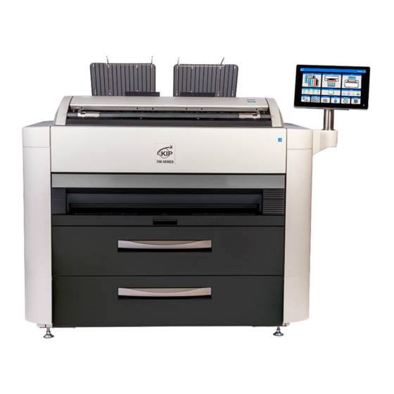
1. 5 Appearance 1. 5. 1 Front view Name of part Function Print Tray These trays catch ejected prints. Scanner Unit Read the original with this unit when you make scan or copy. (MFP model) Scan Abort Button While scanning: emergency stop (MFP model) At Standby position: eject Start Button... -
Page 16: Left Side View
1. 5. 2 Left side view Name of part Function Toner Cover Open here to access the Toner Supply Port. Toner Supply Port Toner Cartridge (C, M, Y, K) to be set here to add toner to the system. Left Door Open here to access Toner Receptacle and jammed sheet inside the printer. -
Page 17: Right Side View
1. 5. 3 Right side view Name of part Function USB Port Your USB flash memory can be used here. (5VDC max.) Power Switch Turn on/off the Printer. 1-10 Chapter 1 Before Use... -
Page 18: Rear View
1. 5. 4 Rear view Name of part Function Fuser Cover Prints come from the opening on this. Open the Fuser Cover when you remove the misfeeds inside the Fuser Unit. Breaker It is possible to shut off supplying the AC power. Inlet Socket Connect the Power Cord here. -
Page 19: Specifications For Print Media
1. 6 Specifications for Print Media 1. 6. 1 Papers not to be used Do not use the following kinds of printing paper. Doing so may damage the print engine. Excessively curled (a diameter of 50 mm or less) Folded Creased Torn Punched... -
Page 20: Paper Storage
Pre-printed Extremely slippery Extremely sticky Extremely thin and soft OHP Film CAUTION Do not use the paper with staple, or do not use such conductive paper as aluminium foil and carbon paper. The above may result in a danger of fire NOTE (1) Print image may become light if printed on a rough surface of the paper. -
Page 21: Environmental Considerations
1. 6. 3 Environmental considerations Take the necessary actions for environmental conditions as shown below. Humidity(%) Possible problem Necessary treatment “Void of image”, “crease of paper” and 1. Install the humidifier in the room, and other problems occurs when you print humidify the room air. -
Page 22: Specifications For Originals
1. 7 Specifications for Originals A scan original must satisfy the following specifications. Thickness 0.05mm to 1.60mm Width 210mm to 914.4mm Length 210mm to 6,000mm NOTE : 1. Image quality for an original with 0.25mm or thicker is guaranteed only in a standard size even the scanner physically accepts it. 2. -
Page 23: "Do Not Scan" Originals
1. 7. 3 “Do Not Scan” Originals It is impossible to use the following types of originals because they are likely to damage the scanner. Do not scan the following kinds of original, because you may damage the original or scanner itself! Sticked with paste Paste Torn... - Page 24 Not square Wet image Made of metal or fabric Metal Fabric Rough surface (Carbon paper for example) Rough surface Clipped or stapled Clipped Stapled 1-17 Chapter 1 Before Use...
- Page 25 The following kinds of originals can be read with using a carrier sheet. However, the image quality and feed reliability are not guaranteed. Patched Punched 1-18 Chapter 1 Before Use...
- Page 26 Chapter 2 Basic Operations page 2. 1 Turning on the Printer 2- 2 2. 2 Turning off the Printer 2- 4 2. 3 Replacing the Roll Media 2- 6 2. 4 Placing Cut Sheet Media 2-13 2. 5 Toner Supply 2-14 2.
-
Page 27: Turning On The Printer
2. 1 Turning on the Printer 1. Plug the Printer to an exclusive wall outlet. WARNING Please confirm the outlet satisfies the following condition before plugging the Printer into. Europe; 220V to 240V plus 10% or minus 10%, 50/60Hz, 16A or higher North America;... - Page 28 4. The Printer will get ready about 6 minutes after turning on. The Status Indicator stops blinking and lights green when ready. Make a copy or print from outer devices. Chapter 2 Basic Operations...
-
Page 29: Turning Off The Printer
2. 2 Turning off the Printer 1. Press “ ” side of the Power Switch. Press this side 2. The Status Indicator light purple while the embedded controller unit is shutting down. It will turn off in few minutes. NOTE The controller unit starts shutdown process after turning off the Printer, and it will take about 1 minute until complete shut down. - Page 30 3. If you completely shut the power supply due to a long vacation or the machine’s transport, turn off the circuit breaker and then remove the power cable from the machine. Chapter 2 Basic Operations...
-
Page 31: Replacing The Roll Media
2. 3 Replacing the Roll Media UI displays a sign of “Roll Replacement” when the used roll media gets empty. Follow the later procedure to load a new roll media. 1. Open the Roll Deck (1) that has empty roll media. With catching the Flanges (2) on both sides, lift and remove the core of roll (3). - Page 32 2. Pull the green lever (4) on each Flange (2), which releases the core of roll (3). Remove both Flanges (2). 3. With sliding the Slide Guides (5) left and right by hand, align them to the width guide lines that match the width of actual media to be loaded.
- Page 33 NOTE (1) Insert Flanges (2) deep enough into the core of roll media until their inside rims surely touch the side face of roll media with having no gap. Inside Rim Inside Rim Correct: Fully inserted Incorrect: There is gap (2) Be careful not to be harmed by the saw-toothed edge (6) when handling the Flanges (2).
- Page 34 6. Fit both Flanges correctly into both Slide Guides (5) in the roll deck. (See next page for more explanation) Chapter 2 Basic Operations...
- Page 35 NOTE (1) Note the position of leading edge. It should be on the top side when directed to the media feeding path. Correct Incorrect to media feeding path to media feeding path to media feeding path Correct : Leading edge is on top side Incorrect : Leading edge is on bottom side (2) The outside rim (7) of the Flange must be aligned with the tip of black triangle (8) for correct gear engagement.
- Page 36 7. Insert the leading edge under the corresponding Feed Roller (10), and then turn the Feed Knob (11) to forward the roll media. Roll 1 & 3 (front) Roll 2 & 4 (rear) 8. Push the Roll Deck (1) back in. NOTE (1) Surely close the Roll Deck until it is locked.
- Page 37 10. Define the media information (media type and width) with using the touch screen. If necessary, press the Trim Button (Scissors icon) or [Trim all] button. Press [OK]. Media Type Media Width NOTE (1) Please set correct type and width settings. Incorrect settings would lead unexpected print results.
-
Page 38: Placing Cut Sheet Media
2. 4 Placing Cut Sheet Media There are several size markings on the Manual Table which indicate possible feed positions. Place a cut sheet in a required size on the table between its concerning size markings then insert it into the Manual Feeder. When the leading edge touches the feeding roller, the machine automatically carries and sets the sheet at the proper position. -
Page 39: Toner Supply
2. 5 Toner Supply Reference When the toner level gets “near to empty”, the screen indicates “Replace Toner”. Please add the requested genuine toner as instructed in the screen. You can add the toner while the printer is in operation. You have two options when “Replace Toner”... - Page 40 1. Open the Toner Cover (1). 2. Gently shake a new Toner Bottle (2) well to loosen the powders inside the bottle. NOTE To make the toner powder smoothly leave from the Toner Bottle on the next step, please ensure the followings. ...
- Page 41 3. Fit the supply hole on the Toner Bottle (3) with the set position of on the Toner Hopper (4). Once the supply hole on the Toner Bottle (3) fits the receipt on the machine side (4) correctly, the Lever will automatically catches the Toner Bottle as shown below. 2-16 Chapter 2 Basic Operations...
- Page 42 4. Fit the Toner Bottle so that the tab part (6) can push the pin (7). Turn the Lever (8) to lock the Toner bottle with the Toner Hopper. 2-17 Chapter 2 Basic Operations...
- Page 43 5. Move the Slide Lever (9) to the arrow direction. Now the toner powder inside the bottle falls in the Toner Hopper. After the most amounts of the toner falls, turn the Toner Bottle body 3 revolutions so that the retaining toner in the Toner bottle can fall. NOTE To use up the toner powder left in the bottle, turn the bottle to either direction, by 3 revolutions.
- Page 44 7. Turn the lever (8) to the original position. 8. With pushing the release lever (9) to the direction of the arrow, detach the Toner Bottle. NOTE The full capacity of the toner hopper is one toner bottle. Do not supply the toner more than the above. WARNING There is combustible powder in the toner cartridge.
- Page 45 9. Press the Toner Recovery button in the touch UI. The printer will properly supply the toner to the imaging section and takes necessary toner refilling actions automatically. The printer goes into “warm up” while processing toner supply. Please wait until the supply is completed.
-
Page 46: Replacing Toner Receptacle
2. 6 Replacing Toner Receptacle When the Toner Receptacle is full, the UI screen shows “Cartridge Full.” The printer does not restart operations until the Toner Receptacle is properly replaced. 1. Assemble the Toner Receptacle as follows. Reference (1) It is easier to assemble by pre-folding beforehand on the fold lines. (2) It is easier to assemble by starting to fold from the side with the toner dropping port. - Page 47 ① ② ③ Release paper ④ 2-22 Chapter 2 Basic Operations...
- Page 48 ⑤ Tape 2 Cover the step on the (Large) side with Tape 2. NOTE Apply the Tape 2 in L-shape to cover the step on the side. Otherwise the step might get caught by the toner receptacle shutter part to prevent from smooth removal of the box. ⑥...
- Page 49 Sheet Support Sheet Support ⑧ Complete Release paper Paste it along the step. 2. Open the Left Door (1). 3. With holding the Toner Receptacle (2) with your hands, bring it up and move it frontward to remove from the machine. 2-24 Chapter 2 Basic Operations...
- Page 50 4. Apply the Tape 2 (Large) (3) to close the opening of the Toner Receptacle, which is included in the Toner Receptacle Kit. WARNING The toner will explode if thrown into a fire. NOTE (1) Do not handle the Toner Receptacle roughly. Otherwise the toner will come out from its open hole.
- Page 51 5. Set the new Toner Receptacle (4) back in the original position. See the following NOTE. NOTE (1) Place the bottom corner of the box at the inside of the positioning step (5). (2) Make sure the clear film windows (6) is not dirty. 2-26 Chapter 2 Basic Operations...
- Page 52 6. Close the Left Door (1). 2-27 Chapter 2 Basic Operations...
-
Page 53: Copying (Mfp Model)
2. 7 Copying (MFP Model) For detailed information to make a copy, please refer to the "GUIDES" in the UI Home screen as well. 1. Press [COPY] in UI Home screen. The screens may vary depending on your system configuration. (Shown with available options) 2. - Page 54 4. The Scanner Unit will start the copy process. Reference Pressing START button may be required to start the scan according to the scanner’s controller software. For further details of “Auto Start”, see the software’s document. Start Button NOTE (1) The scanner unit does not accept originals automatically during Sleep Mode. Tap on the UI screen and then insert an original.
-
Page 55: Stop Of Scan Or Copy (Mfp Model)
2. 8 Stop of Scan or Copy (MFP Model) 1. If necessary, press the Scan Abort Button on the Scanner Unit to immediately stop the original while making a copy or scan. Scan Abort Button Pressing the button stops the current reading a document immediately. The current printing is stopped as well and is ejected. - Page 56 Chapter 3 Error Correction page 3. 1 Mis-feed Error 3- 2 3. 1. 1 Roll Deck Section Jam (Deck 1, 2, 3, 4 Mis-feed) 3- 3 3. 1. 2 Media Feed Section Jam (Registration Mis-feed, Feeder part Mis-feed (3)) 3- 6 3.
-
Page 57: Mis-Feed Error
3. 1 Mis-feed Error "XXXX Mis-feed" is displayed in the UI screen when the media is jammed. The jammed location when displaying "Mis-feed" is shown below. Scanner Section (MFP model) Exit Section Media Feed Section Manual Feeder Section Separation Section Roll Deck Section NOTE (1) Be careful not to get paper cuts on your hand. -
Page 58: Roll Deck Section Jam (Deck 1, 2, 3, 4 Mis-Feed)
3. 1. 1 Roll Deck Section Jam (Deck 1, 2, 3, 4 Mis-feed ) Roll Deck Section Deck 2 Mis-feed Roll Deck Section Deck 1 Mis-feed Roll Deck Section Deck 4 Mis-feed Roll Deck Section Deck 3 Mis-feed 1. Open the Roll Deck in issue. And then rewind the roll onto the media core. 2. - Page 59 3. Set the roll media correctly. Roll 1 & 3 (front) Roll 2 & 4 (rear) NOTE The outside rim of Flange should meet the black triangle marked on Slide Guide. Otherwise the roll media may fall in Roll Deck or result in an incorrect media feeding. Out of position Correct Wrong...
- Page 60 4. Close the Roll Deck. Chapter 3 Error Correction...
-
Page 61: Media Feed Section Jam (Registration Mis-Feed, Feeder Part Mis-Feed (3))
3. 1. 2 Media Feed Section Jam (Registration Mis-feed, Feeder part Mis-feed (3)) Media Feed Section Feeder part Mis-feed (3) Media Feed Section Resistration Mis-feed Chapter 3 Error Correction... - Page 62 Release the Fuser Release Lever (1) to the arrow direction, and then slide the Fuser Unit backward. With paying great attention not to touch the Fuser Unit, remove jammed sheet from between the printer and the Fuser Unit. If you cannot pinch and remove the sheet, go to the next step. If you remove this sheet from the printer, please go to the next step to confirm if there is another sheet in the media path.
- Page 63 Open the Left Door (4). Take out a jammed sheet from the opening. Close the Left Door (4). Chapter 3 Error Correction...
- Page 64 Close the Feeder Unit (Manual Feeder) (3). Press the Fuser Unit to the printer side in place until the Fuser Release Lever clicks. If the Fuser Unit is not set firmly, “Fuser Unit Open” pops up in the UI screen. Chapter 3 Error Correction...
-
Page 65: Separation Section Jam (Separation Mis-Feed (1))
3. 1. 3 Separation Section Jam (Separation Mis-feed (1)) Separation Section Separation Mis-feed (1) Open the Fuser Cover (1). 3-10 Chapter 3 Error Correction... - Page 66 Pinch and gently pull jammed sheet toward you. WARNING (1) There are extremely hot parts inside the Fuser Unit. Do not touch any parts in the Fuser Unit, or you will be burnt. Also the mis-fed media can be very hot. Be careful not to get burnt when you remove it. (2) The stripping claws (2) with a sharp edge are on the inside face of the Fuser Cover.
- Page 67 Release the Fuser Release Lever (3) to the arrow direction, and then slide the Fuser Unit backward. With paying great attention not to touch the Fuser Unit, remove a jammed sheet from between the printer and the Fuser Unit. NOTE In the following cases, open the Feeder Unit (Manual Feeder) as well.
- Page 68 Reference If it is not easy to remove the jammed sheet from either right or left side, please stand in the rear side and use both hands to pull the sheet. For easier access from the rear, remove the Exit Tray 2 (6) and the Exit Tray (7). After removing jammed sheet, return the Exit Tray (7) and the Exit Tray 2 (6) in place.
- Page 69 Take out a jammed sheet from the opening. Close the Left Door (8). Close the Feeder Unit (Manual Feeder) (5). 3-14 Chapter 3 Error Correction...
- Page 70 Press the Fuser Unit to the printer side in place until the Fuser Release Lever clicks. If the Fuser Unit is not set firmly, “Fuser Unit Open” pops up in the UI screen. 10. Close the Fuser Cover (1). 3-15 Chapter 3 Error Correction...
-
Page 71: Exit Section Jam (Exit Back Mis-Feed, Exit Top Mis-Feed)
3. 1. 4 Exit Section Jam (Exit Back Mis-feed, Exit Top Mis-feed) Exit Section Exit Top Mis-feed Exit Section Exit Back Mis-feed When jammed sheet is in the Exit Section, gently pull it out. 3-16 Chapter 3 Error Correction... - Page 72 Open the Fuser Cover (1). Pinch and gently pull jammed sheet toward you. WARNING (1) There are extremely hot parts inside the Fuser Unit. Do not touch any parts in the Fuser Unit, or you will be burnt. Also the mis-fed media can be very hot. Be careful not to get burnt when you remove it. (2) The stripping claws (2) with a sharp edge are on the inside face of the Fuser Cover.
- Page 73 Release the Fuser Release Lever (3) to the arrow direction, and then slide the Fuser Unit backward. With paying great attention not to touch the Fuser Unit, remove jammed sheet from between the printer and the Fuser Unit. NOTE In the following cases, open the Feeder Unit (Manual Feeder) as well. ...
- Page 74 Reference If it is not easy to remove the jammed sheet from either right or left side, please stand in the rear side and use both hands to pull the sheet. For easier access from the rear, remove the Exit Tray 2 (6) and the Exit Tray (7). After removing jammed sheet, return the Exit Tray (7) and the Exit Tray 2 (6) in place.
- Page 75 Take out a jammed sheet from the opening. Close the Left Door (8). Close the Feeder Unit (Manual Feeder) (5). 3-20 Chapter 3 Error Correction...
- Page 76 10. Press the Fuser Unit to the printer side in place until the Fuser Release Lever clicks. If the Fuser Unit is not set firmly, “Fuser Unit Open” pops up in the UI screen. 11. Close the Fuser Cover (1). 3-21 Chapter 3 Error Correction...
-
Page 77: Manual Feeder Section Jam (Feeder Part Mis-Feed (1))
3. 1. 5 Manual Feeder Section Jam (Feeder part Mis-feed (1)) Manual Feeder Section Feeder part Mis-feed (1) 1. Hold the knob (1) and pull out the Bypass Feeder (2). Pull out the mis-feed cut sheet. NOTE The mis-feed cut sheet should be replaced with a new one if its leading edge has a torn or fold. -
Page 78: Scanner Section Jam (Scanner Document Jam) (Mfp Model)
3. 1. 6 Scanner Section Jam (Scanner document jam) (MFP Model) If an original is mis-fed while scanning, the UI screen shows “Scanner document jam”. Follow the instruction below to remove the mis-fed original. 1. Lift up both sides (1) of the Scanner Unit 2. - Page 79 3. 1. 7 Unexpected Interruption / Power Shutdown While in Printing Normally, the printer cuts the media being used and then will stop in case of a media mis-feed. For the following unexpected “while in printing” situations, the printer does NOT cut the media and immediately stops.
- Page 80 4. Pinch and slide the green Tab (8) from one end to the other end at a time. The leading edge section that is coming out from the slit is cut off, and this straightens the leading edge of the roll media.
- Page 81 6. Push the Roll Deck (4) back in. NOTE (1) Surely close the Roll Deck until it is locked. A paper jam may occur if not locked perfectly. (2) Be careful not to catch your finger in between Roll Deck drawers. 7.
- Page 82 10. Confirm if the Power Cord Socket is surely plugged to the wall inlet. Turn on the printer. 11. In the KIP Touch GUI - Home screen, tap the “MEDIA” area. 12. Start “Trim Cut” to the re-wound roll media on the step 5.
-
Page 83: Door Open
3. 2 Door Open "Door Open" is displayed in the UI screen when the door in each unit is opened. 3. 2. 1 Roll Deck (Deck 1 Open, Deck 2 Open) Close the Roll Deck securely to clear "Deck Open". Roll Deck 1 Roll Deck 2 3. -
Page 84: Fuser Cover (Fuser Cover Open)
3. 2. 3 Fuser Cover (Fuser Cover Open) Close the Fuser Cover securely to clear "Fuser Cover Open". Fuser Cover (Exit Door) 3. 2. 4 Left Door (Left Door Open) Close the Left Door securely to clear "Left Door Open". Left Door 3-29 Chapter 3 Error Correction... - Page 85 3. 2. 5 Feeder Unit / Manual Feeder (Manual Feeder Open) Close the Feeder Unit (Manual Feeder) securely to clear "Manual Feeder Open". Feeder Unit (Manual Feeder) 3. 2. 6 Scanner (Scanner Feeder Open) The UI screen shows “Scanner Feeder Open” if the Scanner Unit is open. (not closed properly) Close the Scanner Unit securely to clear "Scanner Feeder open ".
-
Page 86: Other Operator Call
3. 3 Other Operator Call 3. 3. 1 Out of Media When the printer is running out of a loaded roll media, the UI Screen will display “Out of Media” sign. If there is no suitable roll media required for the print job being processed, the UI Screen will prompt “Out of Media”... -
Page 87: Waste Cartridge Full
3. 3. 3 Waste Cartridge Full When the Toner Receptacle is full, the UI screen shows “Waste Cartridge Full.” The printer does not restart operation until the Toner Receptacle is properly replaced. For replacement procedure, see [2.6 Replacing Toner Receptacle]. Toner Receptacle 3-32 Chapter 3 Error Correction... -
Page 88: Service Call Error
3. 4 Service Call Error If an error with significant effect on the printer occurs, the printer stops the operation and indicates the related Service Call Error (Customer Engineer Call Error) in the UI screen. Call your service staff immediately as these problems can be fixed by a well trained technician only. Before calling the service staff, cycle the power of the printer. - Page 89 Chapter 4 Maintenance page 4. 1 Paper Exit section 4- 2 4. 1. 1 Exit Rollers 4- 2 4. 2 Scanner Unit (MFP Model) 4- 5 4. 2. 1 Scan Glass, Feed Roller, Guide Plate 4- 5 4. 2. 2 Sensor 4- 8 4.
-
Page 90: Paper Exit Section Exit Rollers
Before cleaning the printer, turn off the printer, wait two minutes for shutdown, and then disconnect the power cord from the wall outlet. Wipe down the exterior surface with a soft, dry, clean cloth. To prevent the surface of your exterior cover from changing color, do not spray with or apply alcohol or the other volatile substances. - Page 91 NOTE Carefully remove the Exit Tray (3) so as not to touch the clear plastic sheets (4) and the Discharging Brush (5). Clean 6 Exit Rollers (1) of the Paper Exit section to the arrow direction with the cloth which is wrung out the water.
- Page 92 NOTE Carefully clean the Exit Rollers so as not to damage the plastic sheets (4) and the Discharging Brush (5). Reference To clean the entire circumference of the Exit Rollers one time, clean the half circumference of the Exit Rollers and then turn off/on the printer. If so, the Exit Rollers are rotated, and another side (uncleaned side) can be cleaned.
-
Page 93: Scanner Unit (Mfp Model)
4. 2 Scanner Unit (MFP Model) 4. 2. 1 Scan Glass, Feed Roller, Guide Plate It is recommended to clean each Scan Glass, Feeding Rollers and Guide Plates as the scan/copy image may become defective if these parts are dirty. NOTE For ease of visual check, this document shows the Upper Unit fully open (not actual wide). - Page 94 3. Gently wipe the Scan Glass (2) and Feed Rollers (white) (3) with a soft cloth. Equal mixture of water and neutral detergent can be used. NOTE Do not use organic solvent, glass cleaner and anti-static spray for the cleaning. 4.
- Page 95 6. Wipe the Upper Guide Plate (5) and the Lower Guide Plate (6) with a dry cloth. 7. Gently press Scanner Unit down and firmly close it. NOTE Press down Scanner Unit on both side to close it. Do not close it by pressing only one side down. Chapter 4 Maintenance...
-
Page 96: Sensor
4. 2. 2 Sensor If Sensors are dirty, the original may be detected incorrectly. Perform cleaning or as needed. NOTE For ease of visual check, this document shows the Upper Unit fully open (not actual wide). 1. Turn off the Printer. 2. - Page 97 3. Gently wipe Sensors (2) with a dry cotton bud. NOTE Do not use water, organic solvent, glass cleaner or antistatic spray for cleaning. 4. Gently press Scanner Unit down and firmly close it. NOTE Press down Scanner Unit on both sides to close it. Do not close it by pressing only one side down.
-
Page 98: Touch Screen
4. 3 Touch Screen 1. Wipe the Touch Screen with a dry cloth. NOTE Do not use water, alcohol, organic solvent, and glass cleaner for the cleaning. 4-10 Chapter 4 Maintenance... - Page 99 Unit 1508-9, 15/F, Tower A, Regent Centre, 63 Wo Yi Hop Road, Chinese mainland Kwai Chung, N.T., Hong Kong Phone: 852 34269168 KIP (Beijing) Engineering Copying Equipments Co., Ltd. Room 21505,12/F, Building 1, Xing Guang Global New Media Chinese mainland Center, No.39 Chun He Road, Da Xing District, Beijing, China Phone: 86-10-60298900 www.kipchina.com...
- Page 100 WIDE FORMAT COLOR PRINTER / MFP KIP 700 Series Hardware Operation Guide Ver. A.4 (Issued on May 19, 2023) Published by Katsuragawa Electric Co., Ltd. 21-1 Shimomaruko 4-Chome, Ota-ku, Tokyo 146-8585, Japan Please note that some articles, illustrations and photographs might be partially different from the actual machine because of the modification of machine and so on.
- Page 101 KIP 700 C Series User Manual KIP 730 / 740 For SN 1487xxxx Version A.x...
- Page 102 Thank you for purchasing the KIP 700 Series. This Hardware Operation Guide contains functional and operational explanations for the KIP 700 Series. Please read this Hardware Operation Guide carefully before using the Printer. Please keep this Hardware Operation Guide for future reference.
- Page 103 KIP 600 Series is an ENERGY STAR qualified multifunction device. The International NERGY TAR ® Office Equipment Program is an international program that promotes energy saving through the penetration of energy efficient computers and other office equipment. The program backs the development and dissemination of products with functions that effectively reduce energy consumption.
- Page 104 Safety Warning The following warnings are very important in order to safely use this product. These notes are important in preventing danger to the operator or operation of the printer. The following symbols are found throughout the USER’S Manual and have the following meaning: WARNING This WARNING mark means that there is a possibility of death or serious injury if you ignore or do not follow the said instruction.
- Page 105 WARNING Ground the product with a correct ground source or you may be electrically shocked. 1. The Power source should be as follows:208V to 240V plus 6% or minus 10%, 50/60Hz, 16A or higher 2. Use a circuit with a dedicated breaker. 3.
- Page 106 CAUTION 1. Do not install the printer in a humidified room or a dusty room.Also, do not install the printer on an unstable floor as injuries may occur. 2. This equipment is not suitable for use in locations where children are likely to be present.
- Page 107 POWER CORD INSTRUCTION The installation of (or exchange to) a power plug which fits in the wall outlet of the installation location shall be conducted in accordance with the following: WARNING Select a power plug which meets the following criteria; The plug has a voltage and current rating appropriate for the product’s rating marked on its name plate.
- Page 108 Features 1- 4 1. 4 Specifications 1- 5 1. 4. 1 Printer 1- 5 1. 4. 2 Scanner (for KIP 660) 1- 7 1. 5 Appearance 1- 8 1. 5. 1 Front view 1- 8 1. 5. 2 Left side view 1- 9 1.
-
Page 109: Installation Requirements
1. 1 Installation Requirements The following conditions are required for installation of the equipment. 1. Power source should be rated as: 208V - 240V plus 6% or minus 10%, 50/60Hz, 16A or higher 2. The equipment must be on an exclusive circuit. 3. -
Page 110: Originals Prohibited From Duplication
1. 2 Originals Prohibited from Duplication It may be illegal to duplicate or copy certain types of originals and you may be punished by local or regional laws, if copies are made of these types of documents. Please be aware of your local or regional laws and which originals they forbid you to duplicate. Some Examples: [Originals prohibited from copying by law(s)] 1. -
Page 111: Features
1. 3 Features (1) Electro Photographic, full color LED printer/MFP using KIP Contact Control Technology with KIP Contact Array Charging and KIP Image Smoothing Technologies. (2) Models: - KIP 730 : 2 roll wide format color and monochrome printer - KIP 740 : 2 roll wide format color and monochrome MFP (3) Supported widths and lengths: Maximum width : 914mm (36”) -
Page 112: Specifications
1x standard portrait Glossy Paper 1x standard portrait Minimum : 210mm (8.5 inches) NOTE : If the print is longer than the above, KIP does not guarantee image quality or the reliability of the media feeding system. Warm up time... - Page 113 Subject Specification Dimensions KIP 650 : 1500mm (W) x 1035mm (D) x 888mm (H) KIP 660 : 1500mm (W) x 1035mm (D) x 1033mm (H) NOTE: Touch panel and upper trays are not included. Weight KIP 650 ~370 kg KIP 660 ~392 kg...
-
Page 114: Scanner (For Kip 660)
1. 4. 2 Scanner (for KIP 740) Subject Specification Scanning method Contact Image Sensor (CIS) (5 pieces of A4 sized CIS) Light source LED (R/G/B) Scanning speed Monochrome : 65mm/s (600 dpi, normal quality) Grayscale : 65mm/s (max) Color : 22mm/s NOTE: Actual speed may vary by the scan software. -
Page 115: Appearance
Function Print Tray These trays catch ejected prints. Scanner Unit Read the original with this unit when you make scan or copy. (KIP 740 only) Scan Abort Button While scanning: emergency stop At Standby position: eject (KIP 740 only) Start Button Starts scanning if the controlling software requires user intervention. -
Page 116: Left Side View
1. 5. 2 Left side view Name of part Function Toner Supply Port Toner Cartridge (C, M, Y, K) to be set here to add toner to the system. Left Side Door Access Waste Container, Purge Switch and Feeder Release Knob. Waste Toner Box Collects the wasted toner. -
Page 117: Right Side View
1. 5. 3 Right side view Name of part Function USB Port Your USB flash memory can be used here. (5VDC max.) Power Switch Turn on/off the Printer. 1-10 Chapter 1 Before Use... -
Page 118: Rear View
1. 5. 4 Rear view Name of part Function Fuser Cover Prints come from the opening on this. Open the Fuser Cover when you remove the misfeeds inside the Fuser Unit. Breaker It is possible to shut off supplying the AC power. Inlet Socket Connect the Power Cord here. -
Page 119: Specifications For Print Media
1. 6 Specifications for Print Media 1. 6. 1 Papers not to be used Do not use the following kinds of printing paper. Doing so may damage the print engine. Excessively curled (a diameter of 50 mm or less) Folded Creased Torn Punched... -
Page 120: Paper Storage
Pre-printed Extremely slippery Extremely sticky Extremely thin and soft OHP Film CAUTION Do not use the paper with staple, or do not use such conductive paper as aluminium foil and carbon paper. The above may result in a danger of fire NOTE (1) Print image may become light if printed on a rough surface of the paper. -
Page 121: Environmental Considerations
1. 6. 3 Environmental considerations Take the necessary actions for environmental conditions as shown below. Humidity(%) Possible problem Necessary treatment “Void of image”, “crease of paper” and 1. Install the humidifier in the room, and other problems occurs when you print humidify the room air. -
Page 122: Specifications For Originals
1. 7 Specifications for Originals A scan original must satisfy the following specifications. Thickness 0.05mm to 1.60mm Width 210mm to 914.4mm Length 210mm to 6,000mm NOTE : 1. Image quality for an original with 0.25mm or thicker is guaranteed only in a standard size even the scanner physically accepts it. 2. -
Page 123: "Do Not Scan" Originals
1. 7. 3 “Do Not Scan” Originals It is impossible to use the following types of originals because they are likely to damage the scanner. Do not scan the following kinds of original, because you may damage the original or scanner itself! Sticked with paste Paste Torn... - Page 124 Not square Wet image Made of metal or fabric Metal Fabric Rough surface (Carbon paper for example) Rough surface Clipped or stapled Clipped Stapled 1-17 Chapter 1 Before Use...
- Page 125 The following kinds of originals can be read with using a carrier sheet. However, the image quality and feed reliability are not guaranteed. Patched Punched 1-18 Chapter 1 Before Use...
- Page 126 2. 6 Replacing the Toner Receptacle Box 2-27 2. 7 Attaching the Tray C (Asian model only) 2-34 2. 8 Copying (for KIP 660) 2-36 2. 9 Stop of Scan or Copy (for KIP 660) 2-38 Chapter 2 Basic Operations...
-
Page 127: Turning On The Printer
2. 1 Turning on the Printer 1. Plug the Printer to an exclusive wall outlet. WARNING Please confirm the outlet satisfies the following condition before plugging the Printer into. 208V-240V (+6% to -10%), 16A, and 50/60Hz 2. Press “ | ” side of the Power Switch. Press this side 3. - Page 128 4. The Printer will get ready about 6 minutes after turning on. The Status Indicator stops blinking and lights green when ready. Make a copy or print from outer devices. Chapter 2 Basic Operations...
-
Page 129: Turning Off The Printer
2. 2 Turning off the Printer 1. Press “ ” side of the Power Switch. Press this side 2. The Status Indicator light purple while the embedded controller unit is shutting down. It will turn off in few minutes. NOTE The controller unit starts shutdown process after turning off the Printer, and it will take about 1 minute until complete shut down. - Page 130 3. If you completely shut the power supply due to a long vacation or the machine’s transport, turn off the circuit breaker and then remove the power cable from the machine. Chapter 2 Basic Operations...
-
Page 131: Replacing The Roll Media
2. 3 Replacing the Roll Media UI displays a sign of “Roll Replacement” when the used roll media gets empty. Follow the later procedure to load a new roll media. 1. Open the Roll Deck (1) that has empty roll media. With catching the Flanges (2) on both sides, lift and remove the core of roll (3). - Page 132 2. Pull the green lever (4) on each Flange (2), which releases the core of roll (3). Remove both Flanges (2). 3. With sliding the Slide Guides (5) left and right by hand, align them to the width guide lines that match the width of actual media to be loaded.
- Page 133 NOTE (1) Insert Flanges (2) deep enough into the core of roll media until their inside rims surely touch the side face of roll media with having no gap. Inside Rim Inside Rim Correct: Fully inserted Incorrect: There is gap (2) Be careful not to be harmed by the saw-toothed edge (6) when handling the Flanges (2).
- Page 134 6. Fit both Flanges correctly into both Slide Guides (5) in the roll deck. (See next page for more explanation) Chapter 2 Basic Operations...
- Page 135 NOTE (1) Note the position of leading edge. It should be on the top side when directed to the media feeding path. Correct Incorrect to media feeding path to media feeding path to media feeding path Correct : Leading edge is on top side Incorrect : Leading edge is on bottom side (2) The outside rim (7) of the Flange must be aligned with the tip of black triangle (8) for correct gear engagement.
- Page 136 7. Insert the leading edge under the corresponding Feed Roller (10), and then turn the Feed Knob (11) to forward the roll media. Roll 1 Roll 1 Roll 2 Roll 2 2-11 Chapter 2 Basic Operations...
- Page 137 Reference It is recommended to trim the leading edge of the new roll media after installing the roll media. There are two methods of the trim cut, Auto and Manual. Auto: Trim button is available in the UI to take the trim cut automatically. Go to the next step 8. Manual: Operators can use the cutter unit to manually cut the roll media.
- Page 138 Reference Slide the green Tab (14) from one end to the other end at a time. The leading edge section that is coming out from the slit is cut off, and this straightens the leading edge of the roll media. Remove the cut portion.
- Page 139 8. Push the Roll Deck (1) back in. NOTE (1) Surely close the Roll Deck until it is locked. A paper jam may occur if not locked perfectly. (2) Be careful not to catch your finger in between Roll Deck drawers. 2-14 Chapter 2 Basic Operations...
- Page 140 10. Define the media information (media type and width) with using the touch screen. If necessary, press the Trim Button or Trim all Button and finally press [OK]. NOTE (1) Incorrect settings would lead unexpected print results (fusing defect, improper image quality).
-
Page 141: Trim Cut
2. 4 Trim Cut Trim Cut is to straighten the leading edge of an installed roll media. It is recommended to make trim cut in the following situations. After installing a new roll media to the printer After having a paper jam and in case the leading edge of a roll media is torn or folded There are two methods to make trim cut, Auto and Manual. -
Page 142: Manual Cut
2. 4. 2 Manual Cut Open the Roll Deck (1). Feed Knob (2) to forward the roll media. Keep forwarding the roll media until it stops by its leading edge blocked by the next feeding roller. Roll 1 Roll 1 Roll 1 Roll 1 Roll 2... - Page 143 Rotate the Feed Knob (3) in the direction of arrow, and the media is forwarded and comes out from the slit on the rear side of the Roll Deck. Keep forwarding the media until the leading edge comes out by about 100mm. 2-18 Chapter 2 Basic Operations...
- Page 144 Slide the green Tab (4) from one end to the other end at a time. The leading edge section that is coming out from the slit is cut off, and this straightens the leading edge of the roll media. Remove the cut portion. NOTE Please surely follow below instructions when sliding the green Tab (4).
- Page 145 Push the Roll Deck (1) back in. NOTE (1) Surely close the Roll Deck until it is locked. A paper jam may occur if not locked perfectly. (2) Be careful not to catch your finger in between Roll Deck drawers. 2-20 Chapter 2 Basic Operations...
-
Page 146: Toner Supply
2. 5 Toner Supply WARNING There is combustible powder in the toner cartridge. Do not burn up the used toner cartridge. Reference When the toner is empty, the UI Screen will display “Toner Empty” sign. Follow the later procedure (or as noted in the UI’s User Guide) to Supply the Toner with a new one (genuine). - Page 147 3. Fit the supply hole on the Toner Bottle (3) with the set position of on the Toner Hopper (4). Once the supply hole on the Toner Bottle (3) fits the receipt on the machine side (4) correctly, the Lever will automatically catches the Toner Bottle as shown below. 2-22 Chapter 2 Basic Operations...
- Page 148 4. Fit the Toner Bottle so that the tab part (6) can push the pin (7). Turn the Lever (8) to lock the Toner bottle with the Toner Hopper. 2-23 Chapter 2 Basic Operations...
- Page 149 5. Move the Slide Lever (9) to the arrow direction. Now the toner powder inside the bottle falls in the Toner Hopper. Rap the Toner Bottle’s side to remove the remaining toner from inside the Toner bottle 6. After the toner supply to the Toner Hopper is finished, move the slide lever (9) back until it stops at the line (A).
- Page 150 7. Turn the lever (8) to the original position. 8. With pushing the release lever (9) to the direction of the arrow, detach the Toner Bottle. NOTE The full capacity of the toner hopper is one toner bottle. Do not supply the toner more than the above. 2-25 Chapter 2 Basic Operations...
- Page 151 9. Press the Toner Recovery button in the touch UI. Printer will properly transport the toner to the imaging section and takes necessary toner refilling actions automatically. The machine goes into “warm up” while processing toner supply. The machine gets “ready” when the toner refilling completes. ...
-
Page 152: Replacing The Toner Receptacle Box
2. 6 Replacing the Toner Receptacle Box When the Toner Receptacle Box is full, the UI screen shows “Waste Cartridge full.” The printer does not restart operation until the Toner Receptacle Box is properly replaced. 1. Assemble the Toner Receptacle Box as follows. Reference (1) It is easier to assemble by pre-folding beforehand on the fold lines. - Page 153 ① ② ③ Release paper ④ 2-28 Chapter 2 Basic Operations...
- Page 154 ⑤ Tape 2 Cover the step on the (Large) side with Tape 2. NOTE Apply the Tape 2 in L-shape to cover the step on the side. Otherwise the step might get caught by the toner receptacle shutter part to prevent from smooth removal of the box. ⑥...
- Page 155 Sheet Support Sheet Support ⑧ Complete Release paper Paste it along the step. 2. Open the Left Side Cover (1). 3. With holding the Toner Receptacle Box (2) with your hands, bring it up and move it frontward to remove from the machine. 2-30 Chapter 2 Basic Operations...
- Page 156 4. Apply the Tape 2 (Large) (3) to close the opening of the Toner Receptacle Box, which is included in the Toner Receptacle Box Kit. WARNING The toner will explode if thrown into a fire. NOTE (1) Do not handle the Toner Receptacle Box roughly. Otherwise the toner will come out from its open hole.
- Page 157 5. Set the new Toner Receptacle Box (4) back in the original position. See the following NOTE. NOTE (1) Place the bottom corner of the box at the inside of the positioning step (5). (2) Make sure the clear film windows (6) is not dirty. 2-32 Chapter 2 Basic Operations...
- Page 158 6. Close the Left Side Cover (1). 7. Press "Reset" displayed on the UI screen. 2-33 Chapter 2 Basic Operations...
-
Page 159: Attaching The Tray C (Asian Model Only)
2. 7 Attaching the Tray C (Asian model only) Tray C is to help correct stacking of the pages printed using tracing paper and film, which can be placed into position or removed optionally by the operator. Please fit it to its position when printing using tracing paper or film. - Page 160 NOTE The step (3) must be inserted to the 5 slit. If inserted to another slit the ejected pages will not be correctly stacked. Correct : Inserted to the 5 slit The end section of the Too wide Tray C is coming out Incorrect : Inserted to the 4 slit Incorrect : Inserted to the 6...
-
Page 161: Copying (For Kip 660)
2. 8 Copying (for KIP 740) Please refer to the detailed procedure for making a copy, which is included in "GUIDES" in UI Home screen as well. 1. Press [COPY] in UI Home screen. The UI screen may vary depending on your system configuration. - Page 162 4. The KIP 660 will start the copy process. Reference Pressing START button may be required to start the scan according to the scanner’s controller software. For further details of “Auto Start”, see the software’s document. Start Button NOTE (1) The scanner unit does not accept originals automatically during Sleep Mode.
-
Page 163: Stop Of Scan Or Copy (For Kip 660)
2. 9 Stop of Scan or Copy (for KIP 740) 1. If necessary, press the Scan Abort Button on the Scanner Unit to immediately stop the original while making a copy or scan. Scan Abort Button Pressing the button stops the current reading a document immediately. The current printing is stopped as well and is ejected. - Page 164 3- 9 3. 1. 4 Exit Section Jam (Exit Back Mis-feed, Exit Top Mis-feed) 3-12 3. 1. 5 Scanner section Jam (Scanner document jam) (for KIP 660) 3-14 3. 1. 6 Door Open While in Printing 3-15 3. 1. 7...
-
Page 165: Mis-Feed Error
3. 1 Mis-feed Error "XXXX Mis-feed" is displayed in the UI screen when the media is jammed. The jammed location when displaying "Mis-feed" is shown below. Scanner Section Exit Section Media Feed Section Separation Section Roll Deck Section NOTE (1) Be careful not to get paper cuts on your hand. (2) Gently remove a jammed paper. -
Page 166: Roll Deck Section Jam (Deck 1, 2 Mis-Feed)
3. 1. 1 Roll Deck Section Jam (Deck 1, 2 Mis-feed ) Roll Deck Section Deck 2 Mis-feed Roll Deck Section Deck 1 Mis-feed 1. Open the Roll Deck (1) in issue. And then rewind the roll onto the media core. 2. - Page 167 3. Set the roll media correctly. Roll 1 Roll 1 Roll 2 Roll 2 NOTE The outside rim of Flange should meet the black triangle marked on Slide Guide. Otherwise the roll media may fall in Roll Deck or result in an incorrect media feeding. Out of position Correct Wrong...
- Page 168 4. Close the Roll Deck. Chapter 3 Error Correction...
-
Page 169: Media Feed Section Jam (Registration Mis-Feed, Feeder Part Mis-Feed (3))
3. 1. 2 Media Feed Section Jam (Registration Mis-feed, Feeder part Mis-feed (3)) Media Feed Section Feeder part Mis-feed (3) Media Feed Section Resistration Mis-feed 1. Open the Fuser Cover (1). Chapter 3 Error Correction... - Page 170 2. Pinch and gently pull and remove a jammed sheet toward you. WARNING (1) There are extremely hot parts inside the Fuser Unit. Do not touch any parts in the Fuser Unit, or you will be burnt. Also the mis-fed media can be very hot. Be careful not to get burnt when you remove it. (2) The stripping claws (2) with a sharp edge are on the inside face of the Fuser Cover.
- Page 171 Left Side Cover (6). Reference When the Left Side Cover (6) is removed, the KIP Touch UI indicates another status “Left Side Cover Open”. After removing all the sheets, return the Left Side Cover (6) in position and “Left Side Cover Open”...
-
Page 172: Separation Section Jam (Separation Mis-Feed (1))
3. 1. 3 Separation Section Jam (Separation Mis-feed (1)) Separation Section Separation Mis-feed (1) 1. Open the Fuser Cover (1). Chapter 3 Error Correction... - Page 173 2. Pinch and gently pull and remove a jammed sheet toward you. WARNING (1) There are extremely hot parts inside the Fuser Unit. Do not touch any parts in the Fuser Unit, or you will be burnt. Also the mis-fed media can be very hot. Be careful not to get burnt when you remove it. (2) The stripping claws (2) with a sharp edge are on the inside face of the Fuser Cover.
- Page 174 Left Side Cover (6). Reference When the Left Side Cover (6) is removed, the KIP Touch UI indicates another status “Left Side Cover Open”. After removing all the sheets, return the Left Side Cover (6) in position and “Left Side Cover Open”...
-
Page 175: Exit Section Jam (Exit Back Mis-Feed, Exit Top Mis-Feed)
3. 1. 4 Exit Section Jam (Exit Back Mis-feed, Exit Top Mis-feed) Exit Section Exit Top Mis-feed Exit Section Exit Back Mis-feed 1. Open the Fuser Cover (1). 3-12 Chapter 3 Error Correction... - Page 176 2. Pinch and gently pull and remove a jammed sheet toward you. WARNING (1) There are extremely hot parts inside the Fuser Unit. Do not touch any parts in the Fuser Unit, or you will be burnt. Also the mis-fed media can be very hot. Be careful not to get burnt when you remove it. (2) The stripping claws (2) with a sharp edge are on the inside face of the Fuser Cover.
- Page 177 3. 1. 5 Scanner Section Jam (Scanner document jam) (for KIP 660) If an original is mis-fed while scanning, the UI screen shows “Scanner document jam”. Follow the instruction below to remove the mis-fed original. 1. Lift up both sides (1) of the Scanner Unit 2.
-
Page 178: Door Open While In Printing
3. 1. 6 Door Open While in Printing The printer takes a proper “print stop cycle” by cutting the media in printing and indicating the corresponding error/jam code in case of an error/jam. But it does not in an event if either of the Roll Deck, the Fuser Cover or the Left Side Door opens by accident. - Page 179 If the sheet is jammed in Fuser and is not ejected automatically: 1. Close the opened Roll Deck (1), Fuser Cover (2) or Left Side Door (3). 2. Press and hold the Purge Switch (4) until the media is cut. Release the Purge Switch right after the media is cut.
- Page 180 3. Open the Fuser Cover (2), and carefully pull and remove the jammed sheet (5). WARNING (1) There are extremely hot parts inside the Fuser Unit. Do not touch any parts in the Fuser Unit, or you will be burnt. Also the mis-fed media can be very hot.
- Page 181 5. Press and hold the Lever (9) downward and then fully move (pivot) the entire Feeder Unit (10) toward the printer’s front. Take out a remaining (portion of) sheet. 6. Return the Feeder Unit (10), the Left Side Cover (3) and the Fuser Cover (2) in position. 3-18 Chapter 3 Error Correction...
-
Page 182: Unexpected Power Shutdown While In Printing
3. 1. 7 Unexpected Power Shutdown While in Printing In case of an unexpected blackout, turning off the machine by accident or power cord unplugged, the media is not able to be cut by pressing the Purge Switch. Please follow the instruction below. 1. - Page 183 5. Slide the green Tab (8) from one end to the other end at a time. The leading edge section that is coming out from the slit is cut off, and this straightens the leading edge of the roll media. NOTE Please surely follow below instructions when sliding the green Tab.
- Page 184 6. Carefully pull and remove the jammed sheet (9) from the rear. WARNING (1) There are extremely hot parts inside the Fuser Unit. Do not touch any parts in the Fuser Unit, or you will be burnt. Also the mis-fed media can be very hot. Be careful not to get burnt when you remove it. (2) The stripping claws (10) with a sharp edge are on the inside face of the Fuser Cover.
- Page 185 7. Return the Feeder Unit (6), the Left Side Cover (4) and the Fuser Cover (1) in position. 3-22 Chapter 3 Error Correction...
-
Page 186: Door Open
3. 2 Door Open "Door Open" is displayed in the UI screen when the door in each unit is opened. 3. 2. 1 Roll Deck (Deck 1 Open) Close the Roll Deck securely to clear "Deck 1 Open". Roll Deck 3. -
Page 187: Left Side Cover (Left Side Cover Open)
3. 2. 3 Left Side Cover (Left Side Cover Open) Reinstall the Left Side Cover in position to clear “Left Side Cover Open”. The bottom tab portion on the Left Side Cover must fit in the slit on the printer’s side plate. Left Side Cover Slit 3. -
Page 188: Other Operator Call
3. 3 Other Operator Call 3. 3. 1 Roll Replacement When the printer is running out of a loaded roll media, the UI Screen will display “Out of Paper” sign. If there is no suitable roll media required for the current print job, the UI Screen will display “Out of Paper”... -
Page 189: Waste Cartridge Full
3. 3. 3 Waste Cartridge full When the Toner Receptacle Box is full, the UI screen shows “Waste Cartridge Full.” The printer does not restart operation until the Toner Receptacle Box is properly replaced. For replacement procedure, see [2.6 Replacing the Toner Receptacle Box]. Toner Receptacle Box 3-26 Chapter 3 Error Correction... -
Page 190: Service Call Error
3. 4 Service Call Error If an error with significant effect on the printer occurs, the printer stops the operation and indicates a related Customer Engineer Call Error Code (or description, and its equivalent internal code) on the UI screen. Call the service staff immediately as these problems can be fixed by a well trained technician only. - Page 191 4. 1 Paper Exit section 4- 2 4. 1. 1 Exit Rollers 4- 2 4. 2 Scanner Unit (KIP 660 only) 4- 6 4. 2. 1 Scan Glass, Feed Roller, Guide Plate 4- 6 4. 2. 2 Sensor 4- 9 4.
-
Page 192: Paper Exit Section Exit Rollers
4. 1 Paper Exit section 4. 1. 1 Exit Rollers The dirt on the Exit Rollers may be adhered to the cutting face of the trailing part on the print. For this case, please clean 6 Exit Rollers (1) on the Paper Exit section with the cloth which is wrung out the water For the prevention, cleaning these Exit Rollers once a week is recommended. - Page 193 2. Remove 4 screws (M4x10) (3) to remove the Collar (4) and the Exit Tray (5). NOTE 1. Carefully remove the Exit Tray (5) so as not to touch the Mylar (6) and the Discharging Brush (7) each other. 2. The Exit Trays are different between right and left. Please reattach them so that the upper tabs on them should be outside when putting back.
- Page 194 3. Clean 6 Exit Rollers (1) of the Paper Exit section to the arrow direction with the cloth which is wrung out the water. NOTE 1. Clean the Exit Rollers when they are cold; such as "before turning on the printer". 2.
- Page 195 Reference To clean the entire circumference of the Exit Rollers one time, clean the half circumference of the Exit Rollers and then turn off/on the printer. If so, the Exit Rollers are rotated and another side (unclean side) can be cleaned. Chapter 4 Maintenance...
-
Page 196: Scanner Unit (Kip 660 Only)
4. 2 Scanner Unit (KIP 660 only) 4. 2. 1 Scan Glass, Feed Roller, Guide Plate It is recommended to clean each Scan Glass, Feeding Rollers and Guide Plates as the scan/copy image may become defective if these parts are dirty. - Page 197 3. Gently wipe the Scan Glass (2) and Feed Rollers (white) (3) with a soft cloth. Equal mixture of water and neutral detergent can be used. NOTE Do not use organic solvent, glass cleaner and anti-static spray for the cleaning. 4.
- Page 198 6. Wipe the Upper Guide Plate (5) and the Lower Guide Plate (6) with a dry cloth. 7. Gently press Scanner Unit down and firmly close it. NOTE Press down Scanner Unit on both side to close it. Do not close it by pressing only one side down. Chapter 4 Maintenance...
-
Page 199: Sensor
4. 2. 2 Sensor If Sensors are dirty, the original may be detected incorrectly. Perform cleaning or as needed. NOTE For ease of visual check, this document shows the Upper Unit fully open (not actual wide). 1. Turn off the Printer. 2. - Page 200 3. Gently wipe Sensors (2) with a dry cotton bud. NOTE Do not use water, organic solvent, glass cleaner or antistatic spray for cleaning. 4. Gently press Scanner Unit down and firmly close it. NOTE Press down Scanner Unit on both side to close it. Do not close it by pressing only one side down.
-
Page 201: Touch Screen
4. 3 Touch Screen 1. Wipe the Touch Screen with a dry cloth. NOTE Do not use water, alcohol, organic solvent and glass cleaner for the cleaning. 4-11 Chapter 4 Maintenance... - Page 202 Hong Kong / Macao / Kwai Chung, N.T., Hong Kong Chinese mainland Phone: 852 34269168 KIP (Beijing) Engineering Copying Equipments Co., Ltd. Room 21505,12/F, Building 1, Xing Guang Global New Media Chinese mainland Center, No.39 Chun He Road, Da Xing District, Beijing, China Phone: 86-10-60298900 www.kipchina.com...
- Page 203 Please note that some articles, illustrations and photographs might be partially different from the actual machine because of the modification of machine. 2023 Katsuragawa Electric Co., Ltd. No part of this publication may be copied, reproduced or distributed in any form without express written permission from Katsuragawa Electric Co., Ltd.
Need help?
Do you have a question about the 700 C Series and is the answer not in the manual?
Questions and answers