
Subscribe to Our Youtube Channel
Related Manuals for KIP 7970 Series


Summary of Contents for KIP 7970 Series
- Page 1 WIDE FORMAT PRINTER / WIDE FORMAT MULTI FUNCTION PRINTER KIP 7970 Series Hardware Operation Guide Version A.0 May 7, 2016 Carefully read this manual before use. Keep this manual for future reference.
- Page 2 Thank you for purchasing the KIP 7970 Series. This Hardware Operation Guide contains functional and operational explanations for the KIP 7970 Series. Please read this Hardware Operation Guide carefully before using the Printer. Please keep this Hardware Operation Guide for future reference.
- Page 3 KIP 7970 Series is an ENERGY STAR qualified Wide Format Printer / MFP equipment. The International NERGY TAR ® Office Equipment Program is an international program that promotes energy saving through the penetration of energy efficient computers and other office equipment.
-
Page 4: Safety Warning
Safety Warning The following warnings are very important in order to safely use this product. These notes are important in preventing danger to the operator or operation of the printer. The following symbols are found throughout the USER’S Manual and have the following meaning: WARNING This WARNING mark means that there is a possibility of death or serious injury if you ignore or do not follow the said instruction. - Page 5 WARNING Ground the product with a correct ground source or you may be electrically shocked. 1. The Power source should be as follows: 220 to 240V plus 6% or minus 10%, 50/60Hz, 16A or higher 2. Use a circuit with a dedicated breaker. 3.
- Page 6 CAUTION Do not install the printer in a humidified room or a dusty room. Also, do not install the printer on an unstable floor as injuries may occur. 1. Unplug the printer before you move it. The power cord may be damaged and it may result in a fire or electric shock.
- Page 7 POWER CORD INSTRUCTION The installation of (or exchange to) a power plug which fits in the wall outlet of the installation location shall be conducted in accordance with the following: WARNING Select a power plug which meets the following criteria; - The plug has a voltage and current rating appropriate for the product’s rating marked on its name plate.
-
Page 8: Table Of Contents
Chapter 1 Before Use Page 1. 1 Installation Requirements 1- 2 1. 2 Originals Prohibited from Duplication 1- 3 1. 3 Features 1- 4 1. 4 Specifications 1- 5 1. 4. 1 Printer Part 1- 5 1. 4. 2 Scanner Part (for MFP Model) 1- 7 1. -
Page 9: Installation Requirements
1. 1 Installation Requirements The following conditions are required for installation of the equipment. 1. Power source should be rated as follows. 220V - 240V plus 6% or minus 10%, 50/60Hz, 16A or higher 2. The equipment must be on an exclusive circuit. 3. -
Page 10: Originals Prohibited From Duplication
1. 2 Originals Prohibited from Duplication It is not necessarily allowed to copy every kind of original. You may be punished by the law if only you possess the copy of some kind of original. We recommend you to consider enough before you copy such original. [Originals prohibited from copying by the law] 1. -
Page 11: Features
(4) The KIP HDP Plus imaging system produces high definition lines, distinctive greyscale and consistent blacks. (5) Density Compensation Process provides consistent image density in various environments. (6) KIP 7970 Series Printer can make a print in a speed of 160mm per second. - E : 7.6 prints/minute - A0 : 7.2 prints/minute (7) The maximum paper width is 36”... -
Page 12: Specifications
1. 4. 1 Printer Part Subject Specification Model KIP 7970 Series -KIP 7970M : Wide Format MFP with 2 Roll / 4 Roll -KIP 7970P : Wide Format Printer with 2 Roll / 4 Roll Configuration Console Printing method Electro photography... - Page 13 Subject Specification Media (Recommended Media) US model: Plain Paper 64g/m to 80g/m , US Bond (PB-20) Tracing Paper US Vellum (XV-20) Film 4MIL (PF-4DME) Europe/Asia model: Plain Paper 64g/m to 80g/m , Diamond Plain Paper (80g/m Tracing Paper Gateway Tracing Paper (73g/m Film NSF4MIL Film Environmental condition...
-
Page 14: Scanner Part (For Mfp Model)
1. 4. 2 Scanner Part (for MFP Model) Subject Specification Scanning method Contact Image Sensor (CIS) (5 pieces of A4 sized CIS) Light source LED (R/G/B) Scanning speed Monochrome : 65mm/s (600 dpi, normal quality) Grayscale : 65mm/s (max) Colour : 22mm/s NOTE : The actual speed may vary by the scan software. -
Page 15: Appearance
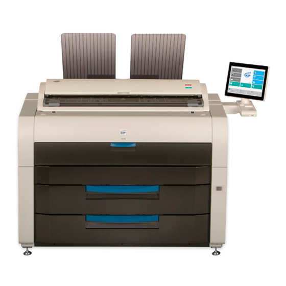
1. 5 Appearance 1. 5. 1 Front Name of part Function User Interface (UI) This is a Touch Screen, and many user operations are available. PLEASE DO NOT push the LCD area too strong. Scanner Unit Read the original with this unit when you make scan or copy. (MFP Model only) Manual Table Open here to insert a cut sheet or to pull the Upper Frame Unit. -
Page 16: Rear
COM Port Connect the cable from a finishing device (option). (D-Sub Connector 9 pins: max.12Vdc (Small)) LAN Port Connect the LAN Cable to connect the KIP 7970 to the network. (Do not connect a telephone line.) Chapter 1 Before Use... -
Page 17: Specifications For Scan Original (For Mfp Model)
1. 6 Specifications for Scan Original (for MFP Model) A scan original must satisfy the following specifications. Thickness 0.05mm to 1.60mm Width 210mm to 914.4mm Length 210mm to 6,000mm NOTE : 1. Suggest to change “It does not guarantee both scan/copy image quality and original feeding reliability in case the original is non- standard size one of which thickness is 0.25mm or thicker. -
Page 18: "Do Not Scan" Originals
1. 6. 3 “Do Not Scan” Originals It is impossible to use the following types of originals because they are likely to damage the scanner. Do not scan the following kinds of original, because you may damage the original or scanner itself! Sticked with paste Paste Torn... - Page 19 Not square Wet image Made of metal or fabric Metal Fabric Rough surface (Carbon paper for example) Rough surface Clipped or stapled Clipped Stapled 1-12 Chapter 1 Before Use...
- Page 20 The following kinds of originals can be read with using a carrier sheet. However, the image quality and feed reliability are not guaranteed. Patched Punched 1-13 Chapter 1 Before Use...
-
Page 21: Specifications For Printing Media
1. 7 Specifications for the Printing Media 1. 7. 1 Papers not available to use Do not use the following kinds of printing paper. Doing so may damage the print engine. Excessively curled (a diameter of 50 mm or less) Folded Creased Torn... -
Page 22: Keeping The Paper In The Custody
Pre-printed Extremely slippery Extremely sticky Extremely thin and soft OHP Film CAUTION Do not use the paper with staple, or do not use such conductive paper as aluminium foil and carbon paper. The above may result in a danger of fire. NOTE (1) Print image may become light if printed on a rough surface of the paper. -
Page 23: Treatment Against Environmental Condition
High keep it in a polyethylene bag. NOTE (1) KIP 7970 Series is equipped with the Dehumidify Heater. Using it in high humidity environment (65% or higher) is recommended. Refer to [2.7 Dehumidifying Roll Media]. (2) “Void of image” and “crease of paper” will occur in case of extremely high or low humidity. - Page 24 NOTE (3) Re-appearance of image (solid black image especially) may occur if you print with a humidified film. When film is installed under the high humidity environment (higher than 60%RH), we also recommend that you turn on the Dehumidify Heater. Normal print Re-appeared image 1-17...
- Page 25 Chapter 2 Basic Operations Page 2. 1 Turning on the Printer 2- 2 2. 2 Turning off the Printer 2- 4 2. 3 Replacing Roll Media 2- 5 2. 4 Replacing Toner Cartridge 2-13 2. 5 Placing Cut Sheet Media 2-17 2.
-
Page 26: Turning On The Printer
2. 1 Turning on the Printer 1. Plug the power cord for Printer into a dedicated wall outlet. WARNING (1) Do not handle the Power Plug with wet hands, or you may receive an electrical shock. (2) Ground the printer for safety. (3) Do not plug the printer into a multi-wiring connector in which other devices are plugged into. - Page 27 3. The User Interface (UI) starts operating, and displays UI Screen in one minute. "Warming Up" is displayed in the status indication while warming up. NOTE It is not possible to print while displaying "Warming Up" in the status indication. 4.
-
Page 28: Turning Off The Printer
2. 2 Turning off the Printer 1. Press “ ” side on the Power Switch to turn off the printer. Press this side. CAUTION (1) The Printer and the UI look to be shut down when you turn off the Printer. However, the embedded controller is still operating in approximately 1 minutes after Power Switch operation for the controller’s shutdown. -
Page 29: Replacing Roll Media
2. 3 Replacing Roll Media Reference (1) When the printer is running out of a roll media, the UI Screen will display “Roll Replacement” sign. Follow the later procedure (or as noted in the UI’s User Guide) to load a roll media. Please refer to your Touch Screen Operator’s Guide for the UI screen. - Page 30 1. Open Roll Deck (1). Holding both Flanges (2), lift and remove a roll media or an empty roll core (3). 2. Raise the green lever (4) on Flange (2). Remove both Flanges (2) from the roll core (3). 3. Hold the shown part of the right Slide Guide (5). Move it to match your roll media’s width. The right and left Side Guides will automatically move together.
- Page 31 4. Insert each Flange (2) into both ends of the roll media core to be installed. NOTE (1) Fully insert Flange into the roll media core so that the inside rim of Flange evenly touches the side face of the roll media. Inside Rim Inside Rim Correct: Fully inserted...
- Page 32 5. Push both the levers (4) down in either way. Position them flat against Flange to secure the roll media. 6. Lift the roll media by holding both Flanges. Lower Flanges onto Slide Guides (5). Chapter 2 Basic Operations...
- Page 33 NOTE (1) Note the rewinding direction. Rear: Deck back Rear: Deck back Front: to media path Front: to media path Correct: Edge comes from bottom Wrong: Edge comes from top (2) The outside rim (7) of Flange should meet the black triangle (8) marked on Slide Guide. Otherwise the roll media may fall in Roll Deck or result in an incorrect media feeding.
- Page 34 7. Insert the leading edge under Guide Plate (9) until it touches the feeding roller (10). Front Deck (Roll 1 / 3) Rear Deck (Roll 2 / 4) Roll 1 Roll 2 Roll 3 Roll 4 2-10 Chapter 2 Basic Operations...
- Page 35 8. Rotate the green knob (11) to the arrow direction (away from front) so that the feeding rollers catch the leading edge. Front Deck (Roll 1 / 3) Rear Deck (Roll 2 / 4) Roll 1 Roll 2 Roll 4 Roll 3 9.
- Page 36 10. When you close Roll Deck, “MEDIA” screen will appear on the UI screen. Choose the correct width and type, and press “Initial Cut” button (with scissors icon) for the corresponding Roll Deck. 2-12 Chapter 2 Basic Operations...
-
Page 37: Replacing Toner Cartridge
(genuine). NOTE (1) The KIP 7970 will indicate Toner Empty sign if an incorrect toner cartridge or no toner cartridge is installed to the printer. (2) At the machine’s installation, some amount of initial toner powders will be supplied to the machine. - Page 38 3. Push the Joint (4) rightward to release the Toner Cartridge. (The joint will be latched on the right.) NOTE Slide the Joint until it clicks to unlock the toner cartridge. Not doing so may damage the toner supply system. 4.
- Page 39 6. Peel off the wrap on the toner supply hole of Toner Cartridge. Shake a new Toner Cartridge several times right and left to make the toner smooth. 7. Press the green lever down until it clicks. Insert the far left pin on Toner Cartridge into the slot firmly.
- Page 40 8. Slightly pull Toner Cartridge rightward and insert the swelling tab in the arrowed slot. 9. Rotate Toner Cartridge to the arrow direction in 180 degrees or more. (The new Toner Cartridge is closed firmly so as not to lose the toner during the transportation) NOTE Even if the Joint is not fit to the Toner Cartridge, when you turn on the printer, it is automatically fit...
-
Page 41: Placing Cut Sheet Media
2. 5 Placing Cut Sheet Media 1. Open Manual Table (1). 2. There are several size markings on Manual Table which indicate possible feed positions. Place a cut sheet in a required size on the table between its concerning size markings then insert it into Manual Feeder. -
Page 42: Copying (For Mfp Model)
2. 6 Copying (for MFP Model) Please refer to the detailed procedure for making a copy, which is included in "GUIDES" in UI Home screen as well. 1. Press [COPY] in UI Home screen. The UI screen may vary depending on your system configuration. (Shown with available options) 2. - Page 43 4. The Printer will start the copy process. Pressing START button may be required to start the scan according to the scanner’s controller software. For further details of “Auto Start”, see the software’s document. Start Button NOTE The scanner unit does not accept originals automatically during Sleep Mode. Tap on the UI screen and then insert an original.
- Page 44 The KIP 7970 Series has 2 print delivery system, the print tray / rear stacking equipment. NOTE For the front stacking, gently lift up the prints on the print tray to the arrow direction to avoid rubbing the print surface. A large number of prints should be removed in several sheets.
-
Page 45: Stop Of Scan Or Copy (For Mfp Model)
2. 7 Stop of Scan or Copy (for MFP Model) 1. If necessary, press the Scan Abort Button on the Scanner Unit to immediately stop the original while making a copy or scan. Scan Abort Button Pressing the button stops the current reading a document immediately. The current printing is stopped as well and is ejected. -
Page 46: Dehumidifying Roll Media
2. 8 Dehumidifying Roll Media If the roll paper is extremely humid, it may cause poor prints. You will experience most likely “creasing” and “voids”. Normal Print Creasing If the media is humidified; Normal Print Voids If the media is humidified; NOTE Re-appearance of image (especially solid black image) may occur if you print with a humidified film. - Page 47 NOTE (1) There are several dehumidifying settings which can be set by service personnel. When these settings are determined, the dehumidifier functions. With any setting, the printer must be plugged in and the switch noted above must be in the “H” position. Call your service personnel if you would like to change the switch setting.
- Page 48 Chapter 3 Error Correction Page 3. 1 Paper Jam 3- 2 3. 1. 1 Roll Deck Section Jam (Deck 1, 2 Mis-feed) 3- 3 3. 1. 2 Manual Feeder Section Jam (By-Pass Mis-feed, Registration Mis-feed) 3- 5 3. 1. 3 Media Feed Section Jam (Mid Feed Mis-feed, Registration Mis-feed, Separation Mis-feed) 3- 6...
-
Page 49: Paper Jam
3. 1 Paper Jam "Paper Jam" is displayed in the UI screen when the media is jammed. The jammed location when displaying "Paper Jam" is shown below. Fuser Section Media Feed Section Manual Feeder Section Roll Deck Section Roll Deck Section NOTE (1) Be careful not to get paper cuts on your hand. -
Page 50: Roll Deck Section Jam
3. 1. 1 Roll Deck Section Jam (Deck 1, 2 Mis-feed ) Roll Deck Section Deck 1 Mis-feed Roll 1 Roll 2 Roll Deck Section Deck 2 Mis-feed Roll 3 Roll 4 1. Open the Roll Deck in issue. And then rewind the roll onto the media core. Roll Deck 2. - Page 51 3. Set the roll media correctly. Front Deck (Roll 1 / 3) Rear Deck (Roll 2 / 4) NOTE The outside rim of Flange should meet the black triangle marked on Slide Guide. Otherwise the roll media may fall in Roll Deck or result in an incorrect media feeding. Out of position Correct Wrong...
-
Page 52: Manual Feeder Section Jam (By-Pass Mis-Feed, Registration Mis-Feed)
3. 1. 2 Manual Feeder Section Jam (By-Pass Mis-feed, Registration Mis-feed) Manual Feeder Section - By-Pass Mis-feed - Registration Mis-feed 1. Pull out the Mis-feed paper from the Manual Feeder, and if the leading edge of the paper is torn or folded, replace it with a new one. -
Page 53: Media Feed Section Jam (Mid Feed Mis-Feed, Registration Mis-Feed, Separation Mis-Feed)
3. 1. 3 Media Feed Section Jam (Mid Feed Mis-feed, Registration Mis-feed, Separation Mis-feed) Media Feed Section - Registration Mis-feed Media Feed Section - Separation Mis-feed Media Feed Section - Mid Feed Mis-feed 1. Open the Manual Table (1). Chapter 3 Error Correction... - Page 54 2. Pull out the Upper Frame Unit (3) to your side (front) with holding both handles (2). 3. Pull up both knobs (4), and then push the Top Cover (5) to rear side. Chapter 3 Error Correction...
- Page 55 4. Remove the mis-fed paper. mis-fed paper 5. Close Top Cover (5). 6. Close Upper Frame Unit (3) and Manual Table (1). Chapter 3 Error Correction...
-
Page 56: Fuser Section Jam (Exit Back Mis-Feed)
3. 1. 4 Fuser Section Jam (Exit Back Mis-feed) Fuser Section - Exit Back Mis-feed 1. Hold the gray handles and open the Paper Exit Door (1). Chapter 3 Error Correction... - Page 57 2. Pull and remove the mis-fed paper to the rear. If you remove the print at this time, just close the mis-fed paper Paper Exit Door. If the print cannot be removed, go to the next step. If the print (including any torn part) can be removed, go to step 6.
- Page 58 5. Close Fuser Door (3) and Paper Exit Door (1). 6. Open the Manual Table (4). 7. Pull out the Upper Frame Unit (5) to your side (front) with holding both handles (6). 3-11 Chapter 3 Error Correction...
- Page 59 8. Pull up both knobs (7), and then push the Top Cover (8) to rear side. 3-12 Chapter 3 Error Correction...
- Page 60 9. Remove the mis-fed paper. mis-fed paper 10. Close Top Cover (8). 11. Close Upper Frame Unit (5) and Manual Table (4). 3-13 Chapter 3 Error Correction...
-
Page 61: Stack Jam
3. 1. 5 Stack Jam 1. Remove print(s) on Print Trays. 2. Pull and remove the mis-fed paper to the top. If the print cannot be removed, see [3.1.4 Fuser Section Jam] for the later procedure of clearing the jammed print. mis-fed paper 3-14 Chapter 3 Error Correction... -
Page 62: Original Jam (For Mfp Model)
3. 1. 6 Original Jam (for MFP Model) If an original is mis-fed while scanning, the UI screen shows “Original Jam”. Follow the instruction below to remove the mis-fed original. 1. Lift up both sides (1) of the Scanner Unit 2. -
Page 63: Door Open
3. 2 Door Open When any deck/cover is open (not closed firmly), the UI Screen will display “Deck Open” or any other prompt screen. Close the concerning deck/cover as it is impossible to print, if this error exists. 3. 2. 1 Roll Deck (Deck 1, 2 Open) “Deck Open”... -
Page 64: Upper Frame Unit / Top Cover (Front Cover Open)
3. 2. 2 Upper Frame Unit / Top Cover (Front Cover Open) If either Upper Frame Unit or Top Cover is open, the UI screen shows “Front Cover Open”. Check if the Upper Frame Unit and the Top Cover are closed firmly. Top Cover Upper Frame Unit Correct: Both Top Cover / Upper Frame Unit closed firmly... -
Page 65: Paper Exit Door (Paper Exit Door Open)
3. 2. 3 Paper Exit Door (Paper Exit Door Open) If Paper Exit Door is open, the UI screen shows “Paper Exit Door Open”. Check if Paper Exit Door is closed firmly. Paper Exit Door 3. 2. 4 Scanner Unit (Scanner feeder open) (for MFP Model) The UI screen shows “Scanner feeder open”... -
Page 66: Other Operator Call
3. 3 Other Operator Call 3. 3. 1 Roll Replacement When the printer is running out of a loaded roll media, the UI Screen will display “Out of Paper” sign. If there is no suitable roll media required for the current print job, the UI Screen will display “Out of Paper”... -
Page 67: Service Call Errors
3. 4 Service Call Errors If an error with significant effect on the printer occurs, the printer stops the operation and indicates a related Customer Engineer Call Error Code (or description, and its equivalent internal code) on the UI screen. Call the service staff immediately as these problems can be fixed by a well trained technician only. - Page 68 Chapter 4 Maintenance Page 4. 1 Scanner Unit (for MFP Model) 4- 2 4. 1. 1 Scan Glass, Feed Roller, Guide Plate 4- 2 4. 1. 2 Sensor 4- 5 4. 2 Touch Screen 4- 7 Chapter 4 Maintenance...
-
Page 69: Scanner Unit (For Mfp Model)
4. 1 Scanner Unit (for MFP Model) 4. 1. 1 Scan Glass, Feed Roller, Guide Plate It is recommended to clean each Scan Glass, Feeding Rollers and Guide Plates as the scan/copy image may become defective if these parts are dirty. NOTE For ease of visual check, this document shows the Upper Unit fully open (not actual wide). - Page 70 3. Gently wipe the Scan Glass (2) and Feed Rollers (white) (3) with a soft cloth. Equal mixture of water and neutral detergent can be used. NOTE Do not use organic solvent, glass cleaner and anti-static spray for the cleaning. 4.
- Page 71 6. Wipe the Upper Guide Plate (5) and the Lower Guide Plate (6) with a dry cloth. 7. Gently press Scanner Unit down and firmly close it. NOTE Press down Scanner Unit on both side to close it. Do not close it by pressing only one side down. Chapter 4 Maintenance...
-
Page 72: Sensor
4. 1. 2 Sensor If Sensors are dirty, the original may be detected incorrectly. Perform cleaning or as needed. NOTE For ease of visual check, this document shows the Upper Unit fully open (not actual wide). 1. Turn off the Printer. 2. - Page 73 3. Gently wipe Sensors (2) with a dry cotton bud. NOTE Do not use water, organic solvent, glass cleaner or antistatic spray for cleaning. 4. Gently press Scanner Unit down and firmly close it. NOTE Press down Scanner Unit on both side to close it. Do not close it by pressing only one side down.
-
Page 74: Touch Screen
4. 2 Touch Screen 1. Wipe the Touch Screen with a dry cloth. NOTE Do not use water, alcohol, organic solvent and glass cleaner for the cleaning. Chapter 4 Maintenance... - Page 75 Hardware Operation Guide Version A.0 (Issued on May 7, 2016) Published by Katsuragawa Electric Co., Ltd. 21-1 Shimomaruko 4-Chome, Ota-ku, Tokyo 146-8585, Japan Company : KIP UK Limited Address : Ground Floor – Magellan House Everdon Park Heartlands Business Park Daventry...
Need help?
Do you have a question about the 7970 Series and is the answer not in the manual?
Questions and answers