Table of Contents
Advertisement
Advertisement
Table of Contents

Subscribe to Our Youtube Channel
Related Manuals for KIP KIP Color 80


Summary of Contents for KIP KIP Color 80
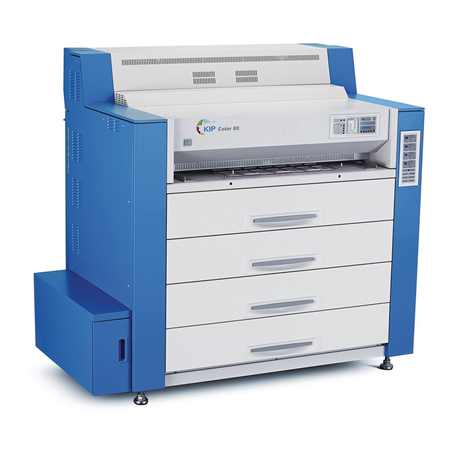
- Page 1 KIP Color 80 Printer Operator’s Guide Guide 2 Version A3...
- Page 2 Republic of China and does not apply to countries outside of People’s Republic of China. NOTE The KIP Color 80 will require a print finisher. Either a KIP print stacker or a KIP folder is available. Please ask your Service or Sale Personnel for details on the optional devices.
-
Page 3: Safety Warnings
Safety Warnings The following warnings are very important in order to safely use this product. These notes are very important in preventing danger to the operator or operation of the printer. The following symbols are found throughout the USER’S Manual and have the following meaning: WARNING This WARNING mark means that there is a possibility of death or serious injury if you ignore or do not follow the said instruction. - Page 4 WARNING Ground the product with a correct ground source or you may be electrically shocked. 1. Connected outlet must satisfy the following condition. 220 to 240V (+6% to -10%), 20A or higher, and 50/60Hz 2. Use a circuit with an exclusive breaker. 3.
- Page 5 CAUTION Do not install the machine in a humidified room or a dusty room. Also, do not install the machine on an unstable floor as injuries may occur. 1. Unplug the printer before you move it. The power cord may be damaged and it may result in a fire or electric shock.
-
Page 6: Table Of Contents
Operation Panel 1-13 1. 5. 5 Media & Toner Information Panel 1-15 Operation Details 1-16 2. 1 Turning on the KIP Color 80 1-16 2. 2 Turning off the KIP Color 80 1-18 2. 3 Replacing the Roll Media 1-19 2. - Page 7 3. 2. 8 Mis-feed around the Transportation Unit 1 Region (Code: J-0121, J-0221 & J-0421) 1-95 3. 2. 9 Mis-feed around the Transportation Unit 2 Region (Code: J-0122, J-0222 & J-0422) 1-100 3. 2.10 Mis-feed around the Transportation Unit 3 Region (Code: J-0123, J-0223 &...
-
Page 8: Before System Use
(see certifications) Ventilate the room, if required. (8) Levelling Bolts on the bottom of the KIP Color 80 should touch the floor correctly. And the equipment must be levelled. Floor strength must be ample to sustain the weight of the equipment. -
Page 9: Originals Prohibited From Duplication
1. 2 Originals Prohibited from Duplication It may be illegal to duplicate or copy certain types of originals and you may be punished by local or regional laws, if copies are made of these types of originals. Please be aware of your local or regional laws and which originals they forbid you to duplicate. Some Examples: [Originals prohibited from copying by the law(s)] 1. -
Page 10: Features
Technology providing exceptional lines and shades. (7) Roll replacement without interrupting print process Roll media can be replaced while the KIP Color 80 is in the process of printing. (8) Long print length The print length is 6 meters (19.7 feet) on plain paper. Up to 45 meters printing is possible... -
Page 11: Specifications
1. 4 Specifications Subject Specification Model KIP Color 80 Type Console Printing method LED - Electro Photography Color CMYK Photoconductor Organic Photoconductive Drums Print speed 80mm / second (3 A0 / minute - 2200 sq. ft. / hour) Exposure method... - Page 12 Subject Specification Environmental condition Temperature 10 to 32.5 degrees centigrade (50 - 89 F) Humidity 30 to 70% RH Storage condition of Print media Wrap the media surely to shut out the humidity. consumables Toner Keep the toner cartridge away from the direct sunlight, and store it in the condition of 0 - 35 and 10 - 85% RH.
-
Page 13: Appearance
Media & Toner Information Panel Name of part Function Power Switch Turns on the KIP Color 80. Bypass Feeder Feeds in the cut sheet media. 50 sheets can be set at once if the media is A2 (594mm) or smaller. (24” or narrower) -
Page 14: Right Side View
1. 5. 2 Right side view Counter B Dehumidify Heater Switch Counter A Fuser Handle Toner Cartridge Cutter Handle Dust Tray Waste Toner Door Waste Toner Box... - Page 15 Name of part Function Cutter Handle Can manually cut the mis-fed media rotating the Cutter Handle. Fuser Handle Can remove the mos-fed media from the Fuser Region safely. Dust Tray Collects the paper dust generated inside of the machine. Dust can be disposed by pulling out the Dust Tray.
-
Page 16: Rear View
1. 5. 3 Rear view Fuser Upper Cover Fuser Cover Transportation Unit 1 Transportation Unit 2 Transportation Unit 3 Transportation Unit 4 AC Main Switch Power Cord Stacker Communication Port USB PC Port (For Service use only) Not used (Interface VIII A ) Interface VIII B (for KCS) Not used - (Folder Port) 1-11... - Page 17 Name of part Function Fuser Upper Cover Can access the media mis-fed around the entrance of the Fuser Unit. Fuser Cover Can access the media mis-fed around the Fuser Unit by opening the Fuser Cover. Transportation Unit 1 Can access the media mis-fed around the Transportation Unit 1. Transportation Unit 2 Can access the media mis-fed around the Transportation Unit 2.
-
Page 18: Operation Panel
1-140 problem. Lights when ready for wire cleaning, flashing for cleaning, off for disabled for cleaning Ready Indicator Flashes green when the KIP Color 80 is warming up. 1-16 Lights green when the KIP Color 80 gets ready. Open Indicator... - Page 19 LED in orange. Menu Key These keys are used in the User Modes. Enter Key Online Key Lights when the KIP Color 80 is online, and goes off when offline. Online Indicator Switches between online and offline. Cancels the User Mode.
-
Page 20: Media & Toner Information Panel
1. 5. 5 Media & Toner Information Panel The Media & Toner Information Panel indicates the information of roll media on each Roll Deck and that of toner of each color independently. Plain Paper Media Type Indicator Vellum/Tracing Media Size Indicator Film Gloss In Use... -
Page 21: Operation Details
220 - 240V (+6% to -10%), 20A, and 50/60Hz 2. Press “|” side of the AC Main Switch on the rear to supply the KIP Color 80 with AC voltage. AC Main Switch 3. Press “|” side of the Power Switch on the front to turn on the KIP Color 80. - Page 22 Refer to [1.3.6.2 Flash of Wire-Clean Key] on page 1-137 for the detail. 5. KIP Color 80 will get ready about 6 minutes after turning on. The Ready Indicator stops flashing and lights green when ready.
-
Page 23: Turning Off The Kip Color
2. 2 Turning off the KIP Color 80 Press “ ” side of the Power Switch on the front to turn off the KIP Color 80. Power Switch NOTE If you will disconnect the power cord, turn off the AC Main Switch at first pressing “O” side then disconnecting the power cord. -
Page 24: Replacing The Roll Media
O n line Reference (1) Even if the KIP Color 80 is printing, a Roll Deck may be able to open without interrupting the printing operation for replacing the roll media. Whether a certain Roll Deck can be opened or not is shown by the corresponding”In Use”... - Page 25 1. Pulling up the handle to unlock the Roll Deck, and draw out the deck. Handle 2. Rotate the Roll Spool one revolution in the direction of arrow to put it out of gear, and then remove it from the Roll Deck. Spool NOTE The Roll Spool is in gear if not rotated in the...
- Page 26 3. Pressing down the green lever to release the core of roll media, and pull out the Roll Spool from the core. Lever 4. Pressing down the green lever, insert the Roll Spool into the new roll media. NOTE Set the roll media in the correct direction. Correct Not correct 1-21...
- Page 27 5. Align the edge of roll media with the concerning size guide, and then release the green lever to fix the roll media onto the Roll Spool firmly. Size guide 6. Install the Roll Spool into the Roll Deck. NOTE The driving rubber belt on the right must be surely placed under the black cylinder of the Roll Spool.
- Page 28 7. As there is a slit for receiving a cutter knife on each Roll Deck, cut off the leading part of roll media to straighten the leading edge. Slit Cutter knife 8. Insert the leading edge of roll media between both feeding rollers, and rotate the upper feeding roller to feed the roll media about 1 or 2cm.
- Page 29 9. Media Selector is on the right of the Roll Deck. Press any of “PLAIN PAPER”, “VELLUM / TRACING”, “FILM” and “GLOSS” according to the type of the installed media. PLAIN PAPER Select when bond (plain) paper is installed. VELLUM/TRACING Select when vellum (tracing paper) is installed.
-
Page 30: Setting Cut Sheet Media To Bypass Feeder
2. 4 Setting Cut Sheet Media to Bypass Feeder Cut sheet media can be fed from the Bypass Feeder. Each size has its own availability for orientation and multi-feeding respectively as follows. Metric Media size Available orientation Availability of Remarks (Length x Width) multi-feeding Landscape... -
Page 31: Multi-Feeding Of Cut Sheet Media
(3) Only landscape position is available in case of multi-feeding. 1. Select the cut sheet feeding mode on the output device connected to the KIP Color 80. Refer to your system reference for media source information. 2. Sliding left and right, place the cut sheet guides properly according to the size of cut sheet media. - Page 32 3. Arrange the edges of multiple media, put them on the Bypass Feeder by landscape position, and move them forward until contacted to feeding roller. Feeding roller NOTE As curled cut sheet media will cause a mis-feed, straighten the media as far as possible before printing.
-
Page 33: Singular Feeding Of Cut Sheet Media
(Put the media in a vinyl bad to block the moisture.) 1. Select the cut sheet feeding mode on the output device connected to the KIP Color 80. Refer to your system reference for media source information. - Page 34 NOTE As curled cut sheet media will cause a mis-feed, straighten the media as far as possible before printing. And also please set the media by “curl down” direction as a mis-feed can be avoided. Setting of media by “curl up” direction tends to result in a mis-feed. Correct (curl down) Incorrect (curl up) 1-29...
-
Page 35: Replacing The Toner Cartridge
2. 5 Replacing the Toner Cartridge The Toner Empty Indicator on the Operation Panel lights red when any of 4 Toner Cartridges is empty. On the Media & Toner Information Panel, the Toner Level Indicator informs which color of Toner Cartridge is empty as all of 4 lamps go off when the concerning color of cartridge is empty. As printing is not available until the cartridge is replaced, replace it as instructed on and after the next page. - Page 36 1. Open the Right Side Door. Right Side Door 2. Rotate the Toner Cartridge 180 degrees in the direction of arrow until it is stopped. Remove the Toner Cartridge from the machine. Toner Cartridge NOTE (1) Toner Cartridge can not be removed if not rotated 180 degrees completely as the above. (2) Do not hold the ventral region of Toner Cartridge.
- Page 37 3. Choose the new Toner Cartridge of the same color, and shake it well to loosen the toner. 4. Insert the Toner Cartridge into the machine with its green seal up. Green seal 5. Rotate the Toner Cartridge 180 degrees in the direction of arrow until it is stopped. 1-32...
- Page 38 6. Strip off the green seal to open the cartridge. Green seal NOTE Toner Empty Indicator will light soon if the supplying hole is directed upward or, if green seal is not removed. 7. Close the Right Side Door. Right Side Door 1-33...
-
Page 39: Replacing The Waste Toner Box
2. 6 Replacing the Waste Toner Box The Waste Toner Full Indicator on the Operation Panel lights red when the Waste Toner Box is completely filled with the wasted toner. Printing is not available until the Waste Toner Box is replaced>Replace it as instructed below. - Page 40 2. Remove the Waste Toner Box. Waste Toner Box NOTE Do not handle the Waste Toner Box roughly. Otherwise the toner will come out from its open hole. 3. Strip off the release paper beside the open hole. Release paper 4.
- Page 41 5. Assemble a folded Waste Toner Box. 6. Strip off the protection papers on 3 tabs, and apply these 3 tabs to the side face of the box folding inward. (1 of 4 tabs can not be applied.) Rear side Front side This tab can not be applied.
- Page 42 7. Holding the free tab, set the Waste Toner Box into the machine so that the hole on the top of the box is located on the rear side. NOTE (1) Direct the free tab upside. Otherwise it may intervene to close the Waste Toner Door. (2) Make sure that the hole on the top of Waste Toner Box is located on the rear side.
-
Page 43: Dehumidifying The Roll Media
2. 7 Dehumidifying the Roll Media A print defect may occur if the roll media is very humid. The usual defects are “crease of media” and “lack of image”. Normal Print Crease of media When media is humidified; Normal Print Lack of image When media is humidified;... - Page 44 2. Press the “H” side of the Dehumidify Heater Switch to turn on the Dehumidify Heater. (Press the “L” side to turn off.) Dehumidify Heater Switch Reference (1) The Dehumidify Heater operates even if the Power Switch is OFF. Be careful not to disconnect the power cord or not to turn off the AC Main Switch.
-
Page 45: Initial Cut (Straighten The Leading Edge Of Roll Media)
NOTE Se le ct When the KIP Color 80 is not available for the Initial Cut by Paper De ck some reason like “warm up” or “door open”, all of 4 lamps of 2 3 4 the Roll Deck Selection Indicator go off. -
Page 46: User Modes
2. 9 User Modes KIP Color 80 provides 14 User Modes. Please note that not all of these modes are to be used and are meant more for service functions. User Mode No. Description User Mode Code User Mode 01... -
Page 47: User Mode 01 (Test Print Start Mode)
2. 9. 1 User Mode 01 (Test Print Start Mode) User Mode 01 can start a Test Print. NOTE When test print is started from User Mode 01, KC80 will perform test printing depending on your specification for “output mode”, “roll deck” and “media type” which can be specified in different user modes respectively. - Page 48 2. Press the Enter Key to start test printing. The KIP Color 80 will perform test printing depending on your test print settings. “Poo” (or “1oo”, “2oo”) on the Status Display flashes during printing. M enu Enter O n line...
-
Page 49: User Mode 02 (Warm Sleep Mode Setting [On/Off, Timer])
Sleep Mode is worked. Reference Warm Sleep Mode is a kind of power saving mode. It works when the KIP Color 80 does not print for the time the timer specifies. Power consumption is reduced by maintaining the temperature of fuser at a lower degree than usual stand by state. - Page 50 4. Press the Enter Key to decide the ON/OFF setting. Then the next setting item “timer setting” becomes available to change. (Setting will be finished when “oFF” was selected.) M enu Enter O n line M enu Enter O n line 5.
-
Page 51: User Mode 03 (Cold Sleep Mode Setting [Timer])
(1) Cold Sleep Mode is a kind of power saving mode that can save more power than Warm Sleep Mode. It works when the KIP Color 80 does not print for the time the timer specifies. Power consumption is reduced greatly by completely shutting off supplying the power to the fuser unit. - Page 52 3. Set the timer for the Cold Sleep Mode selecting a required time pressing [ ] and [ ] keys. Selectable timers are 10, 15, 20, 30, 40, 50, 60, 90, 120, 180, and 240 minutes. M enu Enter O n line M enu Enter O n line...
-
Page 53: User Mode 04 (Temporary Clear E-2132)
2332 and E-2432 is indicated and no more print becomes available. As the user can not clear these errors, the KIP Color 80 will continue to be in breakdown until the error is cleared by the service staff. But if the error can be temporarily cleared in the User Mode 04 by easing the error check level, the KIP Color 80 will be relieved from breakdown and you will be able to continue printing. - Page 54 (1) Online Key will cancel the User Mode 04 when in any stage of the setting. The setting value on changing is not saved in this case. (2) The LCD will continue indicating the error code until the KIP Color 80 is rebooted. 6. Turn off/on the KC80 to reset the error code indication.
-
Page 55: User Mode 05 (Temporary Clear E-2232)
Service call error E-2232 might be temporarily cleared by easing the error check level, which may avoid the breakdown of KIP Color 80. Please see [Reference] on page 1-48 for the detail. 1. Press the Menu Key 5 times to select the User Mode 05. - Page 56 (1) Online Key will cancel the User Mode 05 when in any stage of the setting. The setting value on changing is not saved in this case. (2) The LCD will continue indicating the error code until the KIP Color 80 is rebooted. 6. Turn off/on the KC80 to reset the error code indication.
-
Page 57: User Mode 06 (Temporary Clear E-2332)
Service call error E-2332 might be temporarily cleared by easing the error check level, which may avoid the breakdown of KIP Color 80. Please see [Reference] on page 1-48 for the detail. 1. Press the Menu Key 6 times to select the User Mode 06. - Page 58 (1) Online Key will cancel the User Mode 06 when in any stage of the setting. The setting value on changing is not saved in this case. (2) The LCD will continue indicating the error code until the KIP Color 80 is rebooted. 6. Turn off/on the KC80 to reset the error code indication.
-
Page 59: User Mode 07 (Temporary Clear E-2432)
Service call error E-2432 might be temporarily cleared by easing the error check level, which may avoid the breakdown of KIP Color 80. Please see [Reference] on page 1-48 for the detail. 1. Press the Menu Key 7 times to select the User Mode 07. - Page 60 (1) Online Key will cancel the User Mode 07 when in any stage of the setting. The setting value on changing is not saved in this case. (2) The LCD will continue indicating the error code until the KIP Color 80 is rebooted. 6. Turn off/on the KC80 to reset the error code indication.
-
Page 61: User Mode 08 (Temporary Clear E-2142)
2342 and E-2442 is indicated and no more print becomes available. As the user can not clear these errors, the KIP Color 80 will continue to be in breakdown until the error is cleared by the service staff. But if the error can be temporarily cleared in the User Mode 04 by easing the error check level, the KIP Color 80 will be relieved from breakdown and you will be able to continue printing. - Page 62 (1) Online Key will cancel the User Mode 08 when in any stage of the setting. The setting value on changing is not saved in this case. (2) The LCD will continue indicating the error code until the KIP Color 80 is rebooted. 6. Turn off/on the KC80 to reset the error code indication.
-
Page 63: User Mode 09 (Temporary Clear E-2242)
Service call error E-2242 might be temporarily cleared by easing the error check level, which may avoid the breakdown of KIP Color 80. Please see [Reference] on page 1-56 for the detail. 1. Press the Menu Key 9 times to select the User Mode 09. - Page 64 (1) Online Key will cancel the User Mode 09 when in any stage of the setting. The setting value on changing is not saved in this case. (2) The LCD will continue indicating the error code until the KIP Color 80 is rebooted. 6. Turn off/on the KC80 to reset the error code indication.
-
Page 65: User Mode 10 (Temporary Clear E-2342)
Service call error E-2342 might be temporarily cleared by easing the error check level, which may avoid the breakdown of KIP Color 80. Please see [Reference] on page 1-56 for the detail. 1. Press the Menu Key 10 times to select the User Mode 10. - Page 66 (1) Online Key will cancel the User Mode 10 when in any stage of the setting. The setting value on changing is not saved in this case. (2) The LCD will continue indicating the error code until the KIP Color 80 is rebooted. 6. Turn off/on the KC80 to reset the error code indication.
-
Page 67: User Mode 11 (Temporary Clear E-2442)
Service call error E-2442 might be temporarily cleared by easing the error check level, which may avoid the breakdown of KIP Color 80. Please see [Reference] on page 1-56 for the detail. 1. Press the Menu Key 11 times to select the User Mode 11. - Page 68 (1) Online Key will cancel the User Mode 11 when in any stage of the setting. The setting value on changing is not saved in this case. (2) The LCD will continue indicating the error code until the KIP Color 80 is rebooted. 6. Turn off/on the KC80 to reset the error code indication.
-
Page 69: User Mode 12 (Test Print Setting - Output Mode)
2. 9.12 User Mode 12 (Test Print setting – Output mode) It is possible to set the output mode of Test Print to any of the following 3. Operation mode Description Normal test print mode 1 sheet of internal test pattern is printed out. This is a popular way of test printing, and used for checking the printed image. - Page 70 3. Select any of “Prn”, “C_1” and “C_2” with pressing [ ] and [ ] keys. Prn : Normal test print mode C_1 : Color Registration V calibration mode C_2 : Color Registration H calibration mode M enu Enter O n line M enu Enter O n line...
-
Page 71: User Mode 13 (Test Print Setting - Selection Of Roll Deck)
2. 9.13 User Mode 13 (Test Print setting - Selection of Roll Deck) It is possible to select the Roll Deck used for test printing. 1. Press the Menu Key 13 times to select the User Mode 13. M enu Enter O n line M enu... - Page 72 5. Press the Online Key to cancel the User Mode 13. M enu Enter O n line M enu Enter O n line NOTE Online Key will cancel the User Mode 13 when in any stage of the setting. The setting value on changing is not saved in this case.
-
Page 73: User Mode 14 (Test Print Setting - Selection Of Media Type [Type #X])
2. 9.14 User Mode 14 (Test Print setting - Selection of media type [type #X]) It is possible to specify the media type (type #1 to 4) used for test printing. 1. Press the Menu Key 14 times to select the User Mode 14. M enu Enter O n line... - Page 74 5. Press the Online Key to cancel the User Mode 14. M enu Enter O n line M enu Enter O n line NOTE Online Key will cancel the User Mode 14 when in any stage of the setting. The setting value on changing is not saved in this case.
-
Page 75: Error Messages
General Outlines of Error Codes / Error Indications If any error occurs on the KIP Color 80, the error type and the location are shown on the Operation Panel. Error Indicator region indicates the type of error “by the illustration. - Page 76 Error Code / Error Indication Error Name Reference page for the solution J-0112 Mis-feed around the Bottom Corner 1-92 Region J-0212 J-0412 J-0121 Mis-feed around the Transportation 1-95 Unit 1 Region J-0221 J-0421 J-0122 Mis-feed around the Transportation 1-100 Unit 2 Region J-0222 J-0422 J-0123...
- Page 77 Error Code / Error Name Reference page Error Indication for the solution E-0001 Fuser temperature rising error 1-127 E-0002 Fuser abnormal high temperature error 1-127 E-0020 Fuser thermostat error 1-127 E-0011 Web feeding error 1-127 E-0051 Web end error 1-127 E-1012 Registration roller motor 4 error 1-127...
- Page 78 Error Code / Error Name Reference page Error Indication for the solution E-2321 Image corona 3 output error 1-127 E-2322 Transfer corona 3 output error 1-127 E-2323 Separation corona 3 output error 1-127 E-2324 Developer bias 3 output error 1-127 E-2331 Surface potential sensor 3 error 1-127...
-
Page 79: Mis-Feed Errors (Codes: J-Xxxx)
3. 2 Mis-feed Errors (Codes: J-xxxx) If a mis-feed of printing media occurs anywhere in the KIP Color 80, the Mis-feed Indicator on the Operation Panel lights red. The location of mis-feed is noticed by the lamp indication of the Mis- feed / Open Location Indicator and the “mis-feed code”... - Page 80 NOTE (1) Some sheets of media may be staying in the KIP Color 80 simultaneously as the following picture when mis-feed occurs during a continuous small size printing. Please check the Operation Panel after removing one sheet of media. If the code remains, another media is still staying in the machine.
-
Page 81: Mis-Feed Around The Roll Deck 1 Region
3. 2. 1 Mis-feed around the Roll Deck 1 Region (Code: J-0101, J-0201 & J-0401) When the roll media is mis-fed in the Roll Deck 1, any of J-0101, J-0201 and J-0401 is indicated. (Refer to the following section picture for the location of mis-fed media.) Roll Deck 1 region Remove the mis-fed media as instructed in below. - Page 82 3. Straighten the leading edge by cutting off the damaged part with a cutter knife. NOTE Please straighten the leading edge as the damaged edge will result in a mis-feed again. 4. Insert the leading edge of roll media between both feeding rollers, and rotate the upper feeding roller to feed the roll media about 1 or 2cm.
- Page 83 6. Initial Cut is recommended to straighten the leading edge perfectly. Select the Roll Deck No.1 pressing the SELECT Key, and press the CUT Key to make the Initial Cut for the roll media in the Roll Deck 1. (Details of the Initial Cut are described in [1.2.8 Initial Cut (Straighten the leading edge of roll media)] on page 1-40.) Select Key Cut Key...
-
Page 84: Mis-Feed Around The Roll Deck 2 Region
3. 2. 2 Mis-feed around the Roll Deck 2 Region (Code: J-0102, J-0202 & J-0402) When the roll media is mis-fed in the Roll Deck 2, any of J-0102, J-0202 and J-0402 is indicated. (Refer to the following section picture for the location of mis-fed media.) Roll Deck 2 region Remove the mis-fed media as instructed in below. - Page 85 3. Straighten the leading edge by cutting off the damaged part with a cutter knife. NOTE Please straighten the leading edge as the damaged edge will result in a mis-feed again. 4. Insert the leading edge of roll media between both feeding rollers, and rotate the upper feeding roller to feed the roll media about 1 or 2cm.
- Page 86 6. Initial Cut is recommended to straighten the leading edge perfectly. Select the Roll Deck No.2 pressing the SELECT Key, and press the CUT Key to make the Initial Cut for the roll media in the Roll Deck 2. (Details of the Initial Cut are described in [1.2.8 Initial Cut (Straighten the leading edge of roll media)] on page 1-40.) Select Key Cut Key...
-
Page 87: Mis-Feed Around The Roll Deck 3 Region
3. 2. 3 Mis-feed around the Roll Deck 3 Region (Code: J-0103, J-0203 & J-0403) When the roll media is mis-fed in the Roll Deck 3, any of J-0103, J-0203 and J-0403 is indicated. (Refer to the following section picture for the location of mis-fed media.) Roll Deck 3 region Remove the mis-fed media as instructed in below. - Page 88 3. Straighten the leading edge by cutting off the damaged part with a cutter knife. NOTE Please straighten the leading edge as the damaged edge will result in a mis-feed again. 4. Insert the leading edge of roll media between both feeding rollers, and rotate the upper feeding roller to feed the roll media about 1 or 2cm.
- Page 89 6. Initial Cut is recommended to straighten the leading edge perfectly. Select the Roll Deck No.3 pressing the SELECT Key, and press the CUT Key to make the Initial Cut for the roll media in the Roll Deck 3. (Details of the Initial Cut are described in [1.2.8 Initial Cut (Straighten the leading edge of roll media)] on page 1-40.) Select Key Cut Key...
-
Page 90: Mis-Feed Around The Roll Deck 4 Region
3. 2. 4 Mis-feed around the Roll Deck 4 Region (Code: J-0104, J-0204 & J-0404) When the roll media is mis-fed in the Roll Deck 4, any of J-0104, J-0204 and J-0404 is indicated. (Refer to the following section picture for the location of mis-fed media.) Roll Deck 4 region Remove the mis-fed media as instructed in below. - Page 91 3. Straighten the leading edge by cutting off the damaged part with a cutter knife. NOTE Please straighten the leading edge as the damaged edge will result in a mis-feed again. 4. Insert the leading edge of roll media between both feeding rollers, and rotate the upper feeding roller to feed the roll media about 1 or 2cm.
- Page 92 6. Initial Cut is recommended to straighten the leading edge perfectly. Select the Roll Deck No.3 pressing the SELECT Key, and press the CUT Key to make the Initial Cut for the roll media in the Roll Deck 3. (Details of the Initial Cut are described in [1.2.8 Initial Cut (Straighten the leading edge of roll media)] on page 1-40.) Select Key Cut Key...
-
Page 93: Mis-Feed Around The Bypass Feeder Region
3. 2. 5 Mis-feed around the Bypass Feeder Region (Code: J-0105, J-0205 & J-0405) When the roll media is mis-fed in the Bypass Feeder, any of J-0105, J-0205 and J-0405 is indicated. (Refer to the following section picture for the location of mis-fed media.) Bypass Feeder region NOTE Mis-Feed / Open Location Indicator does not inform the location of the mis-feed in the... -
Page 94: Mis-Feed Around The Cutter Region (Code: J-0111, J-0211 & J-0411)
3. 2. 6 Mis-feed around the Cutter Region (Code: J-0111, J-0211 & J-0411) When the roll media is mis-fed around the Cutter region, any of J-0111, J-0211 and J-0411 is indicated. (Refer to the following section picture for the location of mis-fed media.) Cutter region Remove the mis-fed media as instructed in below. - Page 95 3. Open the Right Side Door again, if it is closed. Right Side Door 4. Rotate the Cutter Handle one revolution in the direction of arrow to cut the roll media manually. Cutter Handle CAUTION (1) Do not rotate the Cutter Handle to the other direction as the cutter blade may be broken. (2) Do not rotate the Cutter Handle more than once.
- Page 96 6. Close the Transportation Unit 4 and Right Side Door. Right Side Door Transportation Unit 4 NOTE Close the Transportation Unit 4 surely and gently. The inside part of machine may be damaged if closed roughly. And the Transportation Unit 4 may not be locked firmly if not closed surely.
-
Page 97: Mis-Feed Around The Bottom Corner Region
3. 2. 7 Mis-feed around the Bottom Corner Region (Code: J-0112, J-0212 & J-0412) When the roll media is mis-fed around the Bottom Corner region, any of J-0112, J-0212 and J-0412 is indicated. (Refer to the following section picture for the location of mis-fed media.) Bottom Corner region Remove the mis-fed media as instructed in below. - Page 98 3. After removing the mis-fed media from the Bottom Corner region, check if some more media is found around there. Whether or not the media is found decides what to do next. • If the media is found as the following left photo, proceed to the next procedure 4 to cut the roll media.
- Page 99 6. Remove the media from the Transportation Unit 4 region. 7. Close the Transportation Unit 4 and Right Side Door (if opened). Right Side Door Transportation Unit 4 NOTE Close the Transportation Unit 4 surely and gently. The inside part of machine may be damaged if closed roughly.
- Page 100 3. 2. 8 Mis-feed around the Transportation Unit 1 Region (Code: J-0121, J-0221 & J-0421) When the roll media is mis-fed around the Transportation Unit 1 region, any of J-0121, J-0221 and J-0421 is indicated. (Refer to the following section picture for the location of mis-fed media.) Transportation Unit 1 region Remove the mis-fed media as instructed in below.
- Page 101 2. Check if the mis-fed is cut or not by pulling from between the Transportation Unit 3 & 4. Whether the media is cut or not decides what to do next. • If the mis-fed media is cut and can be removed from the machine easily, proceed to the following procedure 3.
- Page 102 4. Check if the media is found around the Transportation Unit 4. Whether or not the media is found decides what to do next. • If the media is found as the following left photo, proceed to the next procedure 5 to cut the roll media.
- Page 103 6. Rotate the Cutter Handle one revolution in the direction of arrow to cut the roll media manually. Cutter Handle CAUTION (1) Do not rotate the Cutter Handle to the other direction as the cutter blade may be broken. (2) Do not rotate the Cutter Handle more than once. Otherwise it may result in paper feeding malfunction.
- Page 104 8. Close the Transportation Unit 4 and Right Side Door (if opened). Right Side Door Transportation Unit 4 NOTE Close the Transportation Unit 4 surely and gently. The inside part of machine may be damaged if closed roughly. And the Transportation Unit 4 may not be locked firmly if not closed surely.
- Page 105 3. 2. 9 Mis-feed around the Transportation Unit 2 Region (Code: J-0122, J-0222 & J-0422) When the roll media is mis-fed around the Transportation Unit 2 region, any of J-0122, J-0222 and J-0422 is indicated. (Refer to the following section picture for the location of mis-fed media.) Transportation Unit 2 region Remove the mis-fed media as instructed in below.
- Page 106 2. Check if the mis-fed is cut or not by pulling from between the Transportation Unit 3 & 4. Whether the media is cut or not decides what to do next. • If the mis-fed media is cut and can be removed from the machine easily, proceed to the following procedure 3.
- Page 107 4. Check if the media is found around the Transportation Unit 4. Whether or not the media is found decides what to do next. • If the media is found as the following left photo, proceed to the next procedure 5 to cut the roll media.
- Page 108 6. Rotate the Cutter Handle one revolution in the direction of arrow to cut the roll media manually. Cutter Handle CAUTION (1) Do not rotate the Cutter Handle to the other direction as the cutter blade may be broken. (2) Do not rotate the Cutter Handle more than once. Otherwise it may result in paper feeding malfunction.
- Page 109 8. Close the Transportation Unit 4 and Right Side Door (if opened). Right Side Door Transportation Unit 4 NOTE Close the Transportation Unit 4 surely and gently. The inside part of machine may be damaged if closed roughly. And the Transportation Unit 4 may not be locked firmly if not closed surely.
- Page 110 3. 2.10 Mis-feed around the Transportation Unit 3 Region (Code: J-0123, J-0223 & J-0423) When the roll media is mis-fed around the Transportation Unit 3 region, any of J-0123, J-0223 and J-0423 is indicated. (Refer to the following section picture for the location of mis-fed media.) Transportation Unit 3 region Remove the mis-fed media as instructed in below.
- Page 111 2. Check if the mis-fed is cut or not by pulling from between the Transportation Unit 3 & 4. Whether the media is cut or not decides what to do next. • If the mis-fed media is cut and can be removed from the machine easily, proceed to the following procedure 3.
- Page 112 4. Check if the media is found around the Transportation Unit 4. Whether or not the media is found decides what to do next. • If the media is found as the following left photo, proceed to the next procedure 5 to cut the roll media.
- Page 113 6. Rotate the Cutter Handle one revolution in the direction of arrow to cut the roll media manually. Cutter Handle CAUTION (1) Do not rotate the Cutter Handle to the other direction as the cutter blade may be broken. (2) Do not rotate the Cutter Handle more than once. Otherwise it may result in paper feeding malfunction.
- Page 114 8. Close the Transportation Unit 4 and Right Side Door (if opened). Right Side Door Transportation Unit 4 NOTE Close the Transportation Unit 4 surely and gently. The inside part of machine may be damaged if closed roughly. And the Transportation Unit 4 may not be locked firmly if not closed surely.
- Page 115 3. 2.11 Mis-feed around the Transportation Unit 4 Region (Code: J-0124, J-0224 & J-0424) When the roll media is mis-fed around the Transportation Unit 4 region, any of J-0124, J-0224 and J-0424 is indicated. (Refer to the following section picture for the location of mis-fed media.) Transportation Unit 4 region Remove the mis-fed media as instructed in below.
- Page 116 2. Check if the mis-fed is cut or not by pulling it. Whether the media is cut or not decides what to do next. • If the mis-fed media is cut and can be removed from the machine easily, proceed to the following procedure 3.
- Page 117 5. Rotate the Cutter Handle one revolution in the direction of arrow to cut the roll media manually. Cutter Handle CAUTION (1) Do not rotate the Cutter Handle to the other direction as the cutter blade may be broken. (2) Do not rotate the Cutter Handle more than once. Otherwise it may result in paper feeding malfunction.
- Page 118 7. Close the Transportation Unit 4 and Right Side Door (if opened). Right Side Door Transportation Unit 4 NOTE Close the Transportation Unit 4 surely and gently. The inside part of machine may be damaged if closed roughly. And the Transportation Unit 4 may not be locked firmly if not closed surely.
-
Page 119: Mis-Feed In The Fuser Region (Code: J-0131, J-0231 & J-0431)
3. 2.12 Mis-feed in the Fuser Region (Code: J-0131, J-0231 & J-0431) When the roll media is mis-fed around the Fuser region, any of J-0131, J-0231 and J-0431 is indicated. (Refer to the following section picture for the location of mis-fed media.) Fuser region CAUTION (1) Inside of the covers of the Fuser Region is extremely hot, and the mis-fed media is also... - Page 120 3. Looking into the machine through the open hole on the inside plate, check if the mis-fed is held between the rollers in the Fuser region. Whether or not it is held between the rollers decides what to do next. •...
- Page 121 5. If the leading edge of media is hidden under the parts as the following left photo, pull it out so that the media can be removed undisturbed on later procedure. CAUTION (1) Inside of the covers of the Fuser Region is extremely hot, and the mis-fed media is also hot.
- Page 122 6. Eject the mis-fed media manually by rotate the Fuser Roller Handle in the direction of arrow by hand. Fuser Handle Mis-fed media is ejected. 7. After removing the mis-fed media from the Fuser region, close all the covers and units except for the Transportation Unit 4 Transportation Unit 4.
- Page 123 8. Check if the media is found around the Transportation Unit 4. Whether or not the media is found decides what to do next. • If the media is found as the following left photo, proceed to the next procedure 9 to cut the roll media.
- Page 124 11. Remove the media from the Transportation Unit 4 region. 12. Close the Transportation Unit 4 and Right Side Door. Right Side Door Transportation Unit 4 NOTE Close the Transportation Unit 4 surely and gently. The inside part of machine may be damaged if closed roughly.
-
Page 125: Open Errors (Codes: U-Xxxx)
3. 3 Open Errors (Codes: U-xxxx) If any door, cover or unit is open, the Open Indicator on the Operation Panel lights orange. The location of open item is noticed by the lamp indication of the Mis-feed / Open Location Indicator and the “open code”... -
Page 126: Roll Deck 1 Open (Code: U-0101)
3. 3. 1 Roll Deck 1 open (Code: U-0101) U-0101 is indicated when the Roll Deck 1 is opened or not locked completely. Close the Roll Deck 1 firmly to clear the error. Roll Deck 1 3. 3. 2 Roll Deck 2 open (Code: U-0102) U-0102 is indicated when the Roll Deck 2 is opened or not locked completely. -
Page 127: Roll Deck 4 Open (Code: U-0104)
3. 3. 4 Roll Deck 4 open (Code: U-0104) U-0104 is indicated when the Roll Deck 4 is opened or not locked completely. Close the Roll Deck 4 firmly to clear the error. Roll Deck 4 3. 3. 5 Interlock open (Code: U-0110) U-0110 is indicated when any of the following part is opened. -
Page 128: Bypass Feeder Open (Code: U-0111)
3. 3. 6 Bypass Feeder open (Code: U-0111) U-0111 is indicated when the Bypass Feeder is opened or not locked completely. Close the Bypass Feeder firmly to clear the error. Bypass Feeder 3. 3. 7 Right Side Door open (Code: U-0112) U-0112 is indicated when the Right Side Door is opened or not locked completely. -
Page 129: Transportation Unit 2 Open (Code: U-0122)
3. 3. 9 Transportation Unit 2 open (Code: U-0122) U-0122 is indicated when the Transportation Unit 2 is opened or not locked completely. Close the Transportation Unit 2 firmly to clear the error. Transportation Unit 2 3. 3.10 Transportation Unit 3 open (Code: U-0123) U-0123 is indicated when the Transportation Unit 3 is opened or not locked completely. -
Page 130: Fuser Cover Open (Code: U-0130)
3. 3.12 Fuser Cover open (Code: U-0130) U-0130 is indicated when the Fuser Cover is opened or not locked completely. Close the Fuser Cover firmly to clear the error. Fuser Cover 3. 3.13 Fuser Upper Cover open (Code: U-0131) U-0131 is indicated when the Fuser Upper Cover is opened or not locked completely. -
Page 131: Waste Toner Box Is Not Set (Code: U-0150)
3. 3.15 Waste Toner Box is not set (Code: U-0150) U-0150 is indicated when the Waste Toner Box is not set correctly. Set the Waste Toner Box correctly to clear the error. Waste Toner Box 3. 3.16 Folder Cover open (Code: U-01A1) U-011A1 is indicated when the cover of the Folder is opened or not locked completely. -
Page 132: Call Service Errors (Codes: E-Xxxx)
E nter O n line Before calling the service staff, try to turn on/off the KIP Color 80. If “E-xxxx” is indicated again, turn off the machine, unplug it, and call the service staff with reporting the error code. NOTE (1) The following errors may be cleared temporarily in the User Modes 04, 05, 06 &... - Page 133 Service call error code Error Name E-2115 Image corona 1 cleaning error (Early) E-2116 Image corona 1 cleaning error (Over current) E-2117 Toner cartridge motor 1 error E-2121 Image corona 1 output error E-2122 Transfer corona 1 output error E-2123 Separation corona 1 output error E-2124 Developer bias 1 output error...
- Page 134 Service call error code Error Name E-2414 Image corona 4 cleaning error (Delay) E-2415 Image corona 4 cleaning error (Early) E-2416 Image corona 4 cleaning error (Over current) E-2417 Toner cartridge motor 4 error E-2421 Image corona 4 output error E-2422 Transfer corona 4 output error E-2423...
-
Page 135: Error Indicators
3. 5 Error Indicators The Error Indicators on the Operation Panel informs the type of error. Se lect Cu t Paper Deck W ire -C lean 2 3 4 Copy Den sity M enu Enter O n line Open Indicator Web Cleaner Empty Indicator Toner Empty Indicator Roll Empty Indicator... -
Page 136: Open Indicator
3. 5. 1 Open Indicator The Open Indicator lights orange when any door, cover or unit is open. An open error code is indicated on the Status Display showing the location of open item. Open Indicator Open error code Se lect Cu t Paper Deck W ire -C lean... -
Page 137: Web Cleaner Empty Indicator
3. 5. 2 Web Cleaner Empty Indicator The Web Cleaner Empty Indicator flashes red when the Web Cleaner is near empty. Some more print is still available but it is recommended to inform the service staff that the indicator starts flashing. -
Page 138: Roll Empty Indicator
3. 5. 4 Roll Empty Indicator The Roll Empty Indicator lights red when the used roll media is emptied. See [1.2.3 Replacing the Roll Media] on page 1-19 for the replacement procedure. Roll Empty Indicator Se lect Cu t Paper Deck W ire -C lean 2 3 4 Copy Den sity... -
Page 139: Mis-Feed Indicator
3. 5. 5 Mis-feed Indicator The Mis-feed indicator lights red when a printing media is mis-fed anywhere in the KIP Color 80. A mis-feed code is indicated on the Status Display showing the location of mis-fed media. Mis-feed Indicator Se lect... -
Page 140: Waste Toner Full Indicator
Mis-feed code Error Name Reference page for the solution J-0123 Transportation Unit 3 Region 1-105 J-0223 J-0423 J-0124 Transportation Unit 4 Region 1-110 J-0224 J-0424 J-0131 Fuser Region 1-114 J-0231 J-0431 J-0181 Auto Stacker J-0281 J-0481 J-0182 Folder J-0282 J-0482 3. -
Page 141: Other Indications (Not Error)
Flash of Ready Indicator The Ready Indicator may suddenly starts flashing during normal use. The KIP Color 80 does not make any print when it is lighting even if many jobs are waiting to be printed out. This occurs when the media type is changed from one to another, because it requires changing the temperature of Fuser region. -
Page 142: Flash Of Wire-Clean Key
Paper Deck W ire -C lean 2 3 4 Copy Den sity M enu Enter O n line NOTE Automatic wire cleaning is performed only when the KIP Color 80 is turned on after long term of power off. 1-137... -
Page 143: In Use" Indicator
3. 6. 3 “In Use” Indicator Even if the KIP Color 80 is printing, it may be allowed to open a Roll Deck for replacing the roll media without interrupting the printing operation. Whether a certain Roll Deck can be opened or not during printing is shown by the “In Use”... - Page 144 Reference As the media feeding path runs through the interior of all Roll Decks, the roll media fed from the upper Roll Deck passes through the interior of all the lower Roll Decks. If the media is fed from the 2nd Roll Deck for example, it passes through the 2nd, 3rd and 4th Roll Decks. At this time the “In Use”...
-
Page 145: Treatment For Print Quality Problem
Unnecessary lines When the wire gets dirty; When the KIP Color 80 is not printing, press the Wire-Clean Key on the Operation Panel to start Wire Cleaning. The Wire-Clean Key flashes and printing becomes not available during cleaning. The key stops flashing and printing become available when cleaning is finished. -
Page 146: Lack Of Image
The printing media may be creased when printed in a humid environment. • Store the printing media correctly keeping out the humidity. • Turn on the Dehumidify Heater of the KIP Color 80 referring to [1.2.7 Dehumidifying the Roll Media] on page 1-38. When the media is humidified; Creased 3. -
Page 147: Ips Dashboard
The Request button launches an application that allows color and monochrome image files to be printed on the KIP Color 80 as well as other KIP printers. Features such as print quantity, zoom, basic color adjustment, stamping / watermarks, file viewing, pen control, and folding are only some of the features of this application. -
Page 148: About Tab
4. 2 About Tab The “About” tab displays current versions of software installed on the KIP color 80 IPS. NOTE: The above versions are only an example of the versions and are not necessarily the current versions. 4. 3 Service Tab The “Service”... -
Page 149: Regional Setting
4. 3. 1 Regional Setting This dropdown is used for different regions for keyboard configurations and preferred language. Please select the correct language from the dropdown and press save. 4. 1. 2 Service This area has four sub buttons. (for service use only) a) KC80 Service - launches the engines diagnostics. - Page 150 DIGITAL COLOR PRINTER KIP Color 80 User’s Manual Version A.3 Published by Katsuragawa Electric Co., Ltd. 21-1 Shimomaruko 4-Chome, Ohta-ku, Tokyo 146-8585, Japan All rights reserved. Please note that some articles, illustrations and photographs might differ than the actual machine...
Need help?
Do you have a question about the KIP Color 80 and is the answer not in the manual?
Questions and answers