Table of Contents
Advertisement
Advertisement
Chapters
Table of Contents

Related Manuals for KIP 5000


Summary of Contents for KIP 5000
- Page 1 M o d u l a r, I n t e g r a t e d P r o d u c t i o n S y s t e m User Guide A.3...
- Page 2 Thank you for purchasing the KIP 5000. This USER'S MANUAL contains functional and operational explanations for the KIP 5000. Please read this USER'S MANUAL carefully before using the Printer. Please keep this USER'S MANUAL for future reference. This device complies with part 15 of the FCC Rules. Operation is subject to the following two conditions.
-
Page 3: Safety Warnings
Safety Warnings The following warnings are very important in order to safely use this product. These notes are important in preventing danger to the operator or operation of the printer. The following symbols are found throughout the USER’S MANUAL and have the following meaning: WARNING This WARNING mark means that there is a possibility of death or serious... - Page 4 WARNING Properly Ground the product to a ground source. Failure to do so may result in electrical shock or damage to the equipment. 1. The Power source must be as follows: 120V plus or minus 10%, 16A and 50/60Hz 2. Use a circuit with a dedicated breaker. 3.
- Page 5 CAUTION Do not install the printer in a humidified ordusty room. Do not install the printer on an unstable floor as injuries may occur. 1. Unplug the printer before you move it. Failuer to do so may damage to power cord resulting in fire or electric shock. If the printer will be out of use for an extended period, (holidays, company shutdown) turn off and unplug the printer from the outlet for safety.
- Page 6 TABLE OF CONTENTS Section 1 Basic Printer Functions Section 2 Job Info Mode Section 3 ? Screen Section 4 Windows Drivers Section 5 AutoCAD Drivers Section 6 KIP Request Section 7 KIP PrintNet Section 8 Reporting Section 9 Connectivity...
-
Page 7: Table Of Contents
Section 1 Basic Printer Functions Before Use 1- 3 1. 1 Installation Requirements 1- 3 1. 2 Prohibited Originals 1- 4 1. 3 Key Features 1- 5 1. 4 Specifications 1- 6 1. 5 Exterior Views 1- 7 1. 5. 1 Front view 1- 7 1. - Page 8 Error Correction 1- 56 Paper Mis-feed Errors 1- 56 4. 1. 1 Paper Mis-feed in Roll Deck Section (J-01, J-02, J-03, J-04) 1- 58 4. 1. 2 Paper Mis-feed in Manual Feeder Section (J-05) 1- 60 4. 1. 3 Paper Mis-feed in Paper Feeder Section (J-10, J-11, J-12) 1- 61 4.
-
Page 9: Before Use
Keep ample space around the equipment to ensure comfortable operation. (Refer to the following figure.) The equipment must be levelled and the floor strength must be ample to sustain the weight of the equipment. 100cm or wider Rear side KIP 5000 100cm or 60cm or wider wider Front side... -
Page 10: Prohibited Originals
1. 2 Prohibited Originals Duplication of many documents is prohibited by law! It may be illegal to possess copies of certain types of documents. We recommend you investigate the copyright status of documents and that you ensure you have right to copy / scan a document prior to performing these functions. Originals prohibited from copying / scanning (by law) 1. -
Page 11: Key Features
1. 3 Key Features The KIP 5000 is a single footprint Printer which can also copy and scan with an optional scanner. Advanced drivers and comprehensive print utilities make the KIP 5000 an advanced, easy to use system. Please note that some functions may be optional. -
Page 12: Specifications
1. 4 Specifications Item Specification Model KIP 5000 Configuration Console Printing method LED Array Electro Photography Photoconductor Organic Photoconductive Drum Print speed 3.9 inches per second (100mm / sec) (4 E size or 8 D size in one minute) Resolution... -
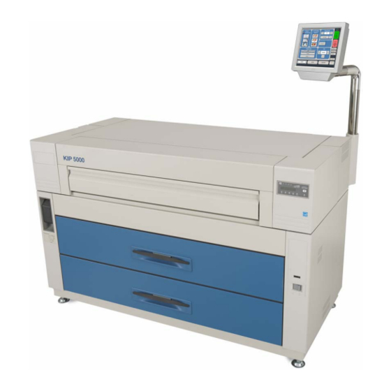
Page 13: Exterior Views
1. 5 Exterior Views 1. 5. 1 Front view Name of part Function Power Switch Press “ON” to turn on the printer, and press “OFF” to turn it off. Counter It counts the total amount printing. (Unit default = sq ft ) Dehumidify Heater Press “H”... -
Page 14: Rear View
Connect to the outlet. Breaker AC power overload protection. Interface Terminal Connect the scanner cable to this terminal, (included with the KIP scanner Model 2200 or 2100 ) USB connector Connect the scanner cable to this terminal (included with the KIP600). -
Page 15: Touchscreen / Sub Display
The following pages only contain notes on the “Job Info” screen which is used in a printer only configuration. Other menus or screens may also be accessible but are detailed in other User Guides. Other screens may be included in alternative options of the KIP 5000. Section 1 Basic Printer Functions... -
Page 16: Job Info Screen
Job Info Screen Name Function Mode Selects the “Mode” of the system. (Job Mode for this screen shown) User Name – Job # Display the User and any user info of the job ID. A job can be selected for other functions noted below. Media Information Displays Width, Type and amount remaining per roll deck Status... - Page 17 Sub Display Panel Toner Low Indicator Roll Empty Indicator Toner Remaining Indicato Paper Mis -feed Indicator Job Indicator Image Density Indicator Ready Indicator Density Selection Key TONER REMAIN IMAGE DENSITY MENU ENTER TEST Test Print Switch Display Enter Key *(Asterisk) Key (Arrow) Key (Arrow) Key Menu Key...
- Page 18 Name of part Functiom Toner Low Indicator Lights when toner is required. Roll Empty Indicator Lights when the roll media in the selected Roll Deck is empty. It can also light when the media is not correctly installed. Paper Mis-feed Indicator Lights when the printer or optional device fails to feed the media.
-
Page 19: Display During Normal Operation
1. 6 Display during Normal Operation The following default screen appears on the touchscreen if the system is only a network printer. Please see other chapters for copy, scan and “?” modes. Roll number, media type and remaining quantity Printer is ready when solid green, warming when flashing All jobs displayed here with current status and can be moved or deleted. - Page 20 (1) Processing a print On the Touchscreen all jobs or prints will be listed as well as the status: List Status On The Sub Display Panel The Job Indicator lights when the printer receives a job. TONER REMAIN IMAGE DENSITY MENU ENTER TEST...
- Page 21 The user can also adjust the density on the printer. Any of the 4 LED’s of the Image Density Indicator will light according to the density level you selected. Image density becomes darker when you select LED’s further to the right. Image Density Indicator TONER REMAIN IMAGE DENSITY...
-
Page 22: Optional Configurations
1. 7 Optional Configurations Standard configuration of the KIP 5000 is Network Printing. Print via TCP/IP from Windows and CAD applications. Included: Windows/PS drivers, AutoDesk Drivers, “KIP Request” job submission utility and “KIP PrintNet” for web based submissions. Please contact your Authorized KIP Dealer for the following options available for the KIP 5000: 1) Copy Adds the advanced functions of copying. -
Page 23: Media Specifications
1. 8 Media Specifications 1. 8. 1 Print Sizes Available print sizes are as follows: Minimum Maximum Width 11 inches (Roll Paper) 36 inches 8.5 inches (Cut Sheet paper) Length 8.5 inches 19.7 ft NOTE It is possible to print longer than 19.7 ft ( 6 m) as an option. You can choose either “24m” or “unlimited”... -
Page 24: Media Not To Be Used
1. 8. 2 Media not to be used Do not use the following kinds of printing paper. Doing so may damage the printer. Excessively curled Folded Creased Torn Punched 1-18 Section 1 Basic Printer Functions... -
Page 25: Maintaining The Media
Pre-printed Extremely slippery Extremely sticky Extremely thin and soft OHP Film CAUTION Do not use paper with staples. Do not use such conductive paper such as aluminium foil and carbon paper. The above may result in fire or damage to the machine. NOTE (1) Print image may become light if printed on the rough surface of the paper. -
Page 26: Environmental Condition - Correction
1. 8. 4 Environmental Condition - Correction Take the necessary actions according to the environmental condition as shown below. Humidity(%) Possible problem Necessary treatment “Void of image”, “crease of paper” 1. Install a humidifier in the room, and and other problems occurs when you humidify the air. - Page 27 NOTE (3) Re-appearance of image (especially solid black images) may occur if you print with a humidified film. When film is installed in a high humidity environment (higher than 60%RH), we recommend that you turn on the Dehumidify Heater. Normal print Re-appeared image 1-21 Section 1 Basic Printer Functions...
-
Page 28: Basic Functions
2. 0 Basic Functions 2. 1 Turning on the Printer 1) Plug the printer into an exclusive wall outlet. WARNING (1) Ground the printer for safety. (2) Do not plug the printer into a multi-wiring connector. It may cause the outlet to overheat resulting in fire, or damage to the machine. - Page 29 3) On the touchscreen upper right corner is an indicator that displays the status of the printer. If it is orange and flashing the printer is warming up. When it is green then the printer is ready to print. Warming up may take up to 8 minutes, from room temperature. Warming Ready 4) There is also an Indicator on the Operation Panel.
-
Page 30: Turning Off The Printer
Press this side. CAUTION The KIP 5000 and the User Interface (UI) appear to be shut down when you turn off KIP 5000, the IPS inside of the KIP 5000 is still operating for approximately 2 minutes after Power Switch operation. -
Page 31: Replacing The Roll Media
2. 3 Replacing the Roll Media NOTE The printer indicates the Roll Empty Error by lighting up the Roll Empty Indicator on the Operation Panel or displays the Empty media screen on the touchscreen. Install new roll media using the following directions Roll Empty Indicator TONER REMAIN IMAGE DENSITY... - Page 32 Open the Roll Deck (1). Rewind the remaining paper around its core as indicated by the arrow. 3) Remove the Roll Spool (2) from the Roll Deck. 4) Pull out the Roll Spool (2) from the core of the roll while pressing down Lever (3).
- Page 33 NOTE Align the top of triangle (6) of stopper and the size mark (7). 6) Insert the Roll Spool into the core until the Stopper (5) touches the roll media while pressing down the Lever (3). Then, release the Lever (3) to “catch” the roll media with the Roll Spool. NOTE Ensure the roll media is wound in the proper direction.
- Page 34 7) Loading Roll 1 or Roll 3 Roll 2 Roll 1 Roll 3 Roll 4 Rear Front 7-1) Put the Roll Spool back into Gear side the Roll Deck. (Gear side is on the left and Lever side is on the right.) NOTE When you place the Roll Spool back into the Roll Deck, make sure to fit the collar of the right side of the Roll Spool into the proper position.
- Page 35 7-2) Rotate the green knob to the direction indicated by the arrow and feed the leading edge of the media between the Feeding Rollers. Roll 2 Roll 1 Knob Knob Roll 3 Roll 4 Rear Front NOTE When you load the media, rotate the Paper Feeding Roller Knob. Do not feed the media too much because the leading edge may come out from the gap.
- Page 36 8) In Loading Roll 2 or Roll 4 Roll 2 Roll 1 Roll 3 Roll 4 Rear Front NOTE Use the “Operator Aid Arm” to load the roll paper onto the deeper Deck (Roll 2 and Roll 4) Follow the above procedure for your safety. Operator Aid Arm 8-1) Place the Roll Spool onto the Operator Aid Arm.
- Page 37 8-2) Slide the right side of the Operator Aid Arm backward. Then slide the left side of the Operator aid Arm backward to install the Roll Spool in the Roll Deck. (Do not slide both sides of the Operator Aid Arm at the same time.) NOTE When you place the Roll Spool back into the Roll Deck, make sure to fit the collar of the right...
- Page 38 8-3) Rotate the green knob as shown by the arrow and feed the leading edge of the media between the Feeding Rollers Knob Roll 2 Roll 1 Roll 3 Roll 4 Rear Front Knob NOTE When you load the media, rotate the Paper Feeding Roller Knob. Do not feed the media too much because the leading edge may come out from the gap.
-
Page 39: Replacing The Toner Cartridge
ENTER TEST Replace the Toner Cartridge with the new KIP 5000 cartridge using the following procedure: (2) If your hands or your clothing are soiled by toner, gently dust off the toner. If you are unable to dust off the toner, wash the clothing with the cold water. (Do not use hot because it will cause the toner to be absorbed into the fiber.) - Page 40 2) Push the Joint (3) rightward to free the Toner Cartridge until the Joint is latched. Joint 3) Press the Lever to left, and then rotate the Toner Cartridge (not the Cap of Cartridge) in the direction indicated by the arrow to close the opening. Approximately 2 rotations closes the opening, but turn the Toner Cartridge until it stops.
- Page 41 5) Shake a new Toner Cartridge several times left to right to evenly distribute the toner. 6) Press the Lever (1) to left, and place the new Toner Cartridge into the machine, ensuring the opening is downward. Insert the far left Collar of the Toner Cartridge into the slot securly. 7) Pull the Toner Cartridge to rightward a little, and insert the notch in the slot.
- Page 42 8) Rotate the Toner Cartridge to backward (in the direction indicated by the arrow) a minimum of 90 degrees. (The new Toner Cartridge is tightly closed during shipment) NOTE Do not fit the joint into the Toner Cartridge. When the machine is turned on, it automatically fits the joint.
-
Page 43: Setting Cut Sheet Paper
2. 5 Setting the Cut Sheet Paper 1) Open the Manual Table. Manual Table Size Mark 2) There are several size mark on the Manual Table. Place the cut sheet paper at the appropriate size mark, and then insert it into the Bypass Feeder using the size mark as a guide. NOTE When the Cut Sheet Paper is inserted manually, its size and media are not indicated on the Operation Panel. -
Page 44: Dehumidifying The Roll Media
2. 6 Dehumidifying the Roll Media If the roll paper is stored in an extremely humid location, it may cause poor prints. You will most likely experience “creasing” and “voids”. Normal Print Creasing If the media contains excess humidity Normal Print Voids If the media contains excess humidity... - Page 45 NOTE (1) There are several dehumidifying settings that can be set by a certified service technician. These settings establish the dehumidifier functions. For any setting to function properly, the printer must be plugged in and the switch noted below must be in the “ON”...
- Page 46 Pull out the Upper Frame Unit to your side. Dehumidify Heater Switch 4) Press “H” side on the switch to turn on the Dehumidify Heater. 1-41 Section 1 Basic Printer Functions...
-
Page 47: User Modes
Most functions of User Modes are Service Functions and you may wish to converse with your local certified KIP Technician prior to enabling any of these modes. Most User Mode functions are performed on the touchscreen in the “?” screen. -
Page 48: User Mode 0: Image Area Expanded
3. 2. 1 User Mode 0: Image Area Expanded Mode Please Set the Touchscreen - “?” Keep this mode always “Off”. (Do not change this setting.) If this function is on, Image Area may expand to right, left and trailing edge side. However, this function does not guarantee the image of the trailing side. -
Page 49: User Mode 1: Image Enhancement Setting
3. 2. 2 User Mode 1: Image Enhancement Setting Mode Please Set the Touchscreen - “?” A weak image can be emphasized by functions such as the Dot Enhancement Level and the Smoothing Function (which can make images it looks clearer). Reference (1) An isolated dot image can be emphasized by the Dot Enhance Level. - Page 50 1) Select “U1.” by pressing [ ] or [ ] key. Applied to the prints TONER REMAIN IMAGE DENSITY MENU ENTER TEST The setting value consists of 2 digits. The left value is not used. The right one is applied to the print from the network.
-
Page 51: User Mode 2: Auto Power Off Timer Setting
3. 2. 3 User Mode 2: Auto Power-Off Timer Setting Mode Please Set the Touchscreen - “?” This mode allows you to set Auto Power-Off Timer. Reference The Auto Power-Off Function cause the Power Switch to turns OFF automatically after a time set in User Mode 2. -
Page 52: User Mode 3: Auto Power Off Setting
3. 2. 4 User Mode 3: Auto Power-Off Setting Mode Please Set the Touchscreen - “?” This mode allows you to select Auto Power-Off function. Reference The Auto Power-Off Function causes the Power Switch to turn OFF automatically at a time set in User Mode 2. -
Page 53: User Mode 4: Cold Sleep Timer Setting
140 degrees Centigrade (284 degrees Fahrenheit) when the KIP 5000 is ready. But if they system is not in use for an extended period, it is best to reduce power consumption by stoping the supply of energy to the heater unit completely. -
Page 54: User Mode 5: Cold Sleep Setting Mode
140 degrees Centigrade (284 degrees Fahrenheit) when the KIP 5000 is ready. But if they system is not in use for an extended period, it is best to reduce power consumption by stoping the supply of energy to the heater unit completely. -
Page 55: User Mode 6: Warm Sleep Timer Setting
The temperature of the heater unit is about 140 degrees Centigrade (284 degrees Fahrenheit) when the KIP 5000 is ready. But if the system is not in use for an extended period, it is advised to reduce power consumption by reducing the temperature of the heater (Temperature is kept at about 120 degrees Centigrade (248 degrees Fahrenheit). -
Page 56: User Mode 7: Warm Sleep Setting
The temperature of the heater unit is about 140 degrees Centigrade (284 degrees Fahrenheit) when the KIP 5000 is ready. But if the system is not in use for an extended period, it is advised to reduce power consumption by reducing the temperature of the heater (Temperature is kept at about 120 degrees Centigrade (248 degrees Fahrenheit). -
Page 57: User Mode 8: Short Interval Setting
3. 2. 9 User Mode 8: Short Interval Setting Mode This mode allows you to set the function “Short Interval”. 1) Select “U8.” by pressing [ ] or [ ] key. TONER REMAIN IMAGE DENSITY MENU ENTER TEST U 8. on : Short Interval function is on. U 8. -
Page 58: User Mode 9: L/L Environment Setting
3. 2.10 User Mode 9: L / L Environment Setting Mode It is possible to select whether or not the L / L Environment Setting Mode is functional. Reference “Creasing of paper” or “Defective fusing” may occur on the prints under the extreme environment of Low Temperature / Low Humidity (called L / L Environment.) You can avoid the above problem if the User Mode 9 is on. - Page 59 3. 2.11 User Mode A: H / H Environment Setting Mode It is possible to select whether or not the H / H Environment Setting Mode is functional. Reference In a high temperature and high humidity environment (called H / H Environment),“creasing of paper”...
- Page 60 1) Select “UA.” by pressing [ ] or [ ] key. TONER REMAIN IMAGE DENSITY MENU ENTER TEST U A. on: H / H Environment Setting is on. U A. off: H / H Environment Setting is off. (Normal operation) 2) Select either “on”...
-
Page 61: Error Correction
4. 0 Error Correction 4. 1 Paper Mis-feed Errors If a paper mis-feed occurs, the Paper Mis-feed Indicator on the Sub Display and a screen on the Touchscreen inform you of the error and the location. The Sub Display indicates a mis-feed code (J-XX) to let you know where the paper is mis-fed. - Page 62 NOTE (1) Remove the mis-fed paper being careful not to cut your hand on the paper edge. (2) Take off necklaces, bracelets, rings and wrist watch before removing the mis-fed paper. Failure to do so may result in burns or electrical shock if the metal accessories touch the interior of the printer.
- Page 63 4. 1. 1 Paper Mis-feed in Roll Deck Section (J-01, J-02, J-03, J-04) When the Paper Mis-feed occurs in the Roll Deck, the Operation Panel indicates a “J-01”, “J-02”, “J-03” or “J-04”. J-01 : Mis-feed in Roll 1 J-02 : Mis-feed in Roll 2 J-03 : Mis-feed in Roll 3 J-04 : Mis-feed in Roll 4 TONER REMAIN...
- Page 64 2) If the leading edge of the media is torn or folded, cut the leading edge of the media. 3) Set the roll media correctly. NOTE When you return the Roll Spool to Roll Deck, make sure to fit the collar on right side of the Roll Spool into proper position as indicated in the following figures.
-
Page 65: Paper Mis-Feed In Manual Feeder Section
4. 1. 2 Paper Mis-feed in Manual Feeder Section (J-05) When the Paper Mis-feed occurs in a Manual Feeder, the Operation Panel indicates a “J-05”. J-05 TONER REMAIN IMAGE DENSITY MENU ENTER TEST Roll 2 Roll 1 Roll 4 Roll 3 Front Rear Clear the Paper Mis-feed by gently pulling out the mis-feed paper. -
Page 66: Paper Mis-Feed In Paper Feeder Section
4. 1. 3 Paper Mis-feed in Paper Feed Section (J-10, J-11, J-12) When the Paper Mis-feed occurs in the Paper Feed Section, Operation Panel indicates “J-10”, “J- 11” or “J-12”. J-10 : Mis-feed in the Front Area J-11 : Mis-feed in the Middle Area J-12 : Mis-feed in the Rear Area J-12 J-11... - Page 67 2) Open the Manual Table. Manual Table Holding both Handles, and then pull out the Upper Frame Unit to your side.You can see the inside of printer. Handle 4) Remove the mis-fed paper from the at the side of printer. 5) Push the Upper Frame Unit back into place.
-
Page 68: Paper Mis-Feed In Fuser Section
4. 1. 4 Paper Mis-feed in Fuser Section (J-13, J-14) When the Paper Mis-feed occurs in the Fuser Section, the Operation Panel indicates “J-13” or “J-14”. J-13, J-14 TONER REMAIN IMAGE DENSITY MENU ENTER TEST Roll 2 Roll 1 TONER REMAIN IMAGE DENSITY Roll 4 Roll 3... - Page 69 2) If it is possible to access the mis-fed paper, gently remove it. Be careful not to tear the mis- fed paper. 3) If it is not possible to access the mis-fed paper from the rear side, lift up the Lever of the Internal Feeder Unit.
- Page 70 Holding both Handles, and then pull out the Upper Frame Unit to your side. Handle 6) Remove the mis-fed paper from the at the side of printer. 7) Push the Upper Frame Unit back into place. 8) Close the Manual Table. 9) Push down the Lever of the Internal Feeder Unit.
- Page 71 4. 1. 5 Paper Mis-feed in Stacker (J-21, J-22) When a paper mis-feed occurs in the Auto Stacker, the Operation Panel indicates either a “J-21” or a “J-22”. TONER REMAIN IMAGE DENSITY TONER REMAIN IMAGE DENSITY MENU ENTER TEST MENU ENTER TEST Refer to the User’s Manual for the stacker to clear the mis-feed.
-
Page 72: Open Cover Errors
4. 2 Open Cover Errors The Sub Display and Touchscreen will indicate an error code if there are any open decks or open covers. Close each deck (or cover) as it is not possible to print, if any are open. 4. -
Page 73: Lever / Toner Cover Open (U-05)
4. 2. 2 Lever / Toner Cover Open (U-05) When either the Lever or the Toner Cover is open the Sub Display indicates a “U-05”. TONER REMAIN IMAGE DENSITY MENU ENTER TEST Toner Cover Close Toner Cover if it is opened. Lever Ensure Lever is securely in place 1-68... -
Page 74: Exit Cover Open (U-06)
4. 2. 3 Exit Cover Open (U-06) When the Exit Cover is opened, the Sub Display indicates “U-06”. TONER REMAIN IMAGE DENSITY MENU ENTER TEST Close the Exit Cover. Exit Cover 1-69 Section 1 Basic Printer Functions... -
Page 75: Other Errors
4. 3 Other Errors 4. 3. 1 Toner Low Flashing The machine indicates “Toner Low” by lighting the Toner Low Indicator on the Sub Display. Toner Cartridge replacement is required. However, if this indicator flashes, it means that this machine is unbalanced. It is not necessary to replace the Toner Cartridge. -
Page 76: No Manual Paper
4. 3. 3 No Manual Paper (P.E.) The machine indicates “P.E.” (Paper Empty) on the Sub Display. Insertion of indicated paper size is required. TONER REMAIN IMAGE DENSITY MENU ENTER TEST Required Paper Size When the Manual Paper is inserted, indication is changed from [P.E.] to [b.p.]. TONER REMAIN IMAGE DENSITY MENU... -
Page 77: Call Service Errors
4. 4 Call Service Errors The following error codes will be displayed on the Sub Display if the machine has a fatal error. It is impossible for the user to resolve these issues. PLEASE CALL YOUR CERTIFIED SERVICE TECHNICIAN TO RESOLVE THESE ERRORS. Error Code Name of the error E - 01... - Page 78 Section 2 Job Info Screen 1. 0 Job Info Screen 2- 2 1.1 Main Screen – Summary 2- 2 2. 0 Operation Details 2- 3 2.1 Job List - Main Screen 2- 3 2.2 User Name 2- 4 2.3 Job – Number 2- 4 2.4 Status 2- 4...
- Page 79 1. 0 Job Info Screen 1.1 Main Screen Name Function Mode Selects the “Mode” of the system. (Job Mode for this screen shown) User Name – Job # Display the User and any user info for the job ID. A job can be selected for other functions noted below.
-
Page 80: Operation Details
2. 0 Operation Details The Job Info screen is used to view or manage the current copy or prints jobs on the KIP 5000. 2.1 Job List - Main Screen All jobs that are currently printing or are waiting to print are displayed in this area. -
Page 81: User Name
Displays the “Name” or the “owner” of the job This information is obtained from fields within: a) KIP Request b) KIP Windows Driver c) KIP AutoCAD Driver d) Or from the Accounting Fields on the copier when accounting is enabled... -
Page 82: Status
Status Displays the current “Status” of a job. Displays one of the following: a) Processing – job is currently printing b) On Hold – puts the job in the queue but will not print until a valid media type is applied c) Vellum –... -
Page 83: Delete
2.7 Delete To remove a job from the Job list: a) Select the job to remove Another Screen will appear. b) Press the Delete button c) The job will be removed from the list. Section 2 Job Info Screen... - Page 84 2.8 Change Media Type in Print Job To change the media type in a job that may be in the job list: a) Select the job b) Job Information screen will appear. c) Press the Bond, Vellum or Film button to set the new media type for this job.
-
Page 85: Pause
To Top If a job in the list is required urgently and there are other jobs in the list prior to it, the job can be moved to the top of the queue. a) Select the job from the list b) Press the “To Top”... -
Page 86: Page Scroll
2.12 Media Information At the top of the Job List Screen is the region that displays the current media loaded in KIP 5000. Please note that only rolls the printer has will be displayed. -
Page 87: Change Media Information
2.13 Change Media Information At the top of the Job List Screen is the region that displays the current media loaded in KIP 5000. Please note that only rolls the printer has will be displayed. a) Touch any area of this region to the set media type and width in all roll decks... -
Page 88: Job History
2.14 Job History KIP Job History can be used to call up and print jobs that were previously printed. By selecting a job from the Job History list, the job can be changed and resubmitted for printing. 1. To use the KIP Job History select the Job Info Button and click on the Current Job button 2. - Page 89 4. Users have the option to change Accounting information, Media type, Number of Originals and number of sets. Or to delete the job from History. 5. When all changes (if any) are complete select the Submit button to send the job to the printer.
- Page 90 Section 3 “?” Screen 1.0 ? – Configuration Screen ................... 3- 2 1.1 Overview ....................3- 2 1.2 “?” Screen – General................. 3- 3 2.0 Main Screen - Details..................3- 4 2.1 Information Region..................3- 4 2.1.1 Meter A..................3- 4 2.1.2 Total Run..................
-
Page 91: Configuration Screen
The KIP 5000 has the ability to display information about the system and allow detailed configuration or setting of the KIP 5000 for Copy and Scan modes. It also has visual user guides which can assist the user in perform the functions of the KIP 5000. -
Page 92: Screen - General
User Guide Enters the Graphical Users Guides. Configuration Enters the settings and configurations modes. Print This Screen Prints the main “?” screen on the KIP 5000 Service Password protected area for KIP authorized technician use. Color Config Configures the optional color scan and color copy features. -
Page 93: Main Screen - Details
“reset” if care is not taken upon replacement of the DC Controller. Please see KIP 5000 Service Manual for details on the setting procedures. In case of discrepancies: The hard counter shall be taken as the correct value! Section 3 ?”... -
Page 94: Total Run
2.1.8 IPS Number Displays the current IPS number, this is required for any optional upgrades to the KIP 5000. 2.1.9 Machine Serial Number Displays the KIP 5000 hardware serial number, this is also located on the lower rear of the printer. NOTE If this serial number differs from the “hard coded”... -
Page 95: Supplier / Technical Support
2.2 Supplier / Technical Support This region displays the contact information for KIP 5000 supplies and service. This region should display your local Authorized KIP dealers’ information. If this information is incorrect, please contact your KIP dealer. Section 3 ?” Screen... -
Page 96: User Guides
3.0 User Guides Press the User Guides button to gain access to the KIP 5000 User Guides on the KIP 5000. The User guides cover the most basic functions of the system operations including media / toner replacement on the KIP 5000. For comprehensive details please consult this User Manual. -
Page 97: Configuration
4.0 Configuration There are five pages in the Configuration. Page 1 of 5 4.1 Printer Density Sets the printer density for all images, including copy and print jobs Section 3 ?” Screen... -
Page 98: Power Save Settings
4.2 Power Save Settings The KIP 5000 incorporates timers to save power and place the printer in “cold sleep mode” to suit individual company production requirements. These timers can be used to automatically turn off the printer when the “office is closed”, for example overnight. -
Page 99: Master Lead / Trail Adjustment
4.5 Test pattern A variety of test patterns may be printed from the KIP 5000 operator panel on an on-demand basis. The following four predefined test patterns are available to assist in pen table selection and overall quality verification. -
Page 100: Options
4.6 Options Enables options on the KIP 5000, contact your local dealer for more details and for the KeyCode for your system. NOTE Incorrect codes will prevent your system from functioning. Please do not enter or modify the current code without permission. The codes may be locked and access may only be granted by a certified service technician. -
Page 101: Language
Set the system from “English Mode” to “Metric Mode” by pressing the English or Metric button. This will effect the entire KIP 5000 System, including Scan, Print and Copy. Please note that the printer must be set to the correct size mode for proper print function. -
Page 102: Copy And Scan Menu Defaults
4.11 Copy and Scan Menu Defaults Each KIP 5000 system provides powerful options regarding the preferred condition of the system upon start up. KIP 5000 system operators may designate features to be active when the system is powered on to ensure efficient use. -
Page 103: Fold
4.12 Fold Sets the system to accept fold parameter loaded by KIP Request and enables the pull downs on the screens. Please contact your local certified service technician for configuration of this feature. 4.13 Cut Sheet Enables / Disables the cut sheet function, which may not be required in certain installation. -
Page 104: Reset Job Info
This button will restart the IPS, when the system is not responding / printing correctly. 4.17 Current Time Set the current time using the arrow buttons. Please note that the Time Zone may need to be set. Please contact your Local KIP Dealer to set the correct Time Zone. 3-15 Section 3... -
Page 105: Color Configuration
This menu will allow a) A third party printer to be connected to the KIP IPS. b) The KIP scanner to be calibrated to the third party printer and media type. This is a simple closed loop calibration. Manufacturer... - Page 106 Destination IP The third party printer will have an IP address assigned to spool data to it. Please enter the IP address here. Please contact your local IT administrator for this information. 3-17 Section 3 ?” Screen...
- Page 107 After the scan is completed, the IPS will automatically calibrate the scanner - media – mode. It will place a “check” beside the calibrated mode, set the date it was calibrated and allow function of this mode in color Copy and Scan Modes of the KIP 5000.
-
Page 108: Other Buttons
6.1 Service This button is used by a certified service technician to access the service functions of the IPS. It is password protected to prevent unwanted changes to the KIP 5000. 6.2 Print This Screen This button will print the main “?” screen. This include the meter counts, versions, etc. This can be useful for troubleshooting or for record keeping. - Page 109 Section 4 Windows Driver Page 1. 0 Introduction 4- 2 1.1 Introduction 4- 2 1.2 Option Screen – Overview 4- 3 2. 0 Function / Feature Details 4- 4 2.1 Output Format 4- 4 2.2 Orientation 4- 5 2.3 Scaling 4- 5 2.4 Copies 4- 5...
- Page 110 Windows NT4 / 2000 / XP / x64 Operating systems, as well as 2003 Server based applications. The KIP Unified Windows Printer Driver is available for download from your local KIP website and is also supplied with your KIP 5000 Printer on the software CD. Section 4 Windows Driver...
- Page 111 1.2 Option Screen - Overview Beginning at the top of the layout above, these are the main features on the KUWPD Name Feature / Function Output Format Selects the type of “language” for driver output Orientation Rotation of the page Scaling Allows scaling of an image to the page size if not supported in the application.
-
Page 112: Output Format
KIP dealer for details. NOTE When using the KIP GL output format, the Default.PEN - Pen Table at the KIP Controller will also control some of the printing features. Features such as Vector Line Dither Pattern, RTL Raster Dither, RTL Density, and Line Width Compensation are used during conversion for printing. -
Page 113: Paper Size
This feature allows printing onto a media type of your choice of an installed kind. 2.6 Paper Size Select the output page size. Please note that the KIP printer may have a roll installed that may be larger than the selection. Section 4... - Page 114 Job Number c) Description Unified Accounting – The Windows Driver points to a central location Ex. A KIP 5000 which has a centralized list and rules for accounting. For information on how to set up unified Accounting please see the Request or PrintNet sections.
-
Page 115: Mirrored Output
If an optional folding device is installed onto the printer, select fold to allow the printer to determine which fold table to apply to the document. The patterns must be set by a certified service technician in the KIP 5000 IPS. 2.12 Mirrored Output The image can be mirrored as required by the user. - Page 116 2.14 Stamps The KIP Windows driver will read the list of available stamps that are configured on the KIP IPS. It is not possible to modify these stamps using the driver. For information on configuring stamps, please see the KIP Request documentation.
- Page 117 (Windows 9x platforms not supported). The driver can be downloaded from your local KIP website and is included on your KIP 5000 Software CD. This driver may also be obtained from KIP PrintNET. Please see the PrintNET documentation for more information.
- Page 118 Execute printman.exe from a Microsoft Windows NT4, 2000, XP, x64 or 2003 operating system. An installation window is displayed: b) Select the appropriate KIP Printer from the Model Name drop down selection (kip 5000). Do not change the Name and Source Fields.
- Page 119 Choose Server/Workstation from Installation Location. g) Do not change Destination Directory. h) Provide the IP address OR hostname of your KIP printer for IPS Name or IP Address. It is important to add EITHER the hostname OR the IP address. Do not add both.
- Page 120 Right-Click on “KIP Printer” and select Printing Preferences. User Interface is displayed. For Microsoft Windows NT4, select Document Defaults. l) The following settings will determine the initial defaults for the printer driver. These defaults are acquired from client workstations connecting to the shared printer driver.
- Page 121 The printman.exe utility is designed to automate the installation of the KIP Port Monitor (KIP0) and the KIP Unified Windows Printer Driver (KUWPD). It is possible to install both components manually. Manual installation techniques may be necessary to satisfy IT and/or corporate requirements.
- Page 122 Choose Server/Workstation from Installation Location h) Do not change Destination Directory i) Provide the IP address OR hostname of your KIP printer for IPS Name or IP Address. It is important to add EITHER the hostname OR the IP address. Do not add both.
- Page 123 LPR Byte Counting enabled. LPR/LPD implementation requires a Queue Name to be defined. Use KIP as the queue name, in all uppercase lettering. This is the name of the printer object on the KIP IPS by default.
- Page 124 c) From the Control Panel - Printers menu select “Add Printer”. When the Printer Wizard dialog is displayed* select Local printer attached to this computer. Click Next * Microsoft Windows NT4 screens will vary slightly from those shown 4-16 Section 4 Windows Driver...
- Page 125 d) Select Using the Following Port, and assign KIP0, or use KIP1, KIP2 depending on the installation. Select Next. e) Install Printer Software dialog is displayed. Click Have Disk. 4-17 Section 4 Windows Driver...
- Page 126 KUWPD / WIN2000 = Microsoft Windows 2000 Workstation / Server KUWPD / WINXP = Microsoft Windows XP, x64, Microsoft Windows 2003 Server g) Select the appropriate KIP Printer from the list displayed and click Next. h) Provide a Printer Name when prompted. Select Next. 4-18...
- Page 127 i) Assign a shared name (if applicable)*. Select Next * If replacing a previously shared driver, it is possible to use the same share name. j) Determine if you would like to print a Test Page when prompted. Select Next. 4-19 Section 4 Windows Driver...
- Page 128 Installed printer can now be accessed from the Microsoft Printer Control Panel* * If printer is not seen, press F5 to refresh the printer list m) Right-Click KIP printer and select Printing Preferences*. User Interface is displayed. * For Microsoft Windows NT4, select Document Defaults p) The following settings will determine the initial defaults for the printer driver.
- Page 129 Management functions*, and Header information. * See Printing Hints section later in this document o) Click OK when finished. NOTE If you wish to add additional KIP Printers, use the Add-Printer-Wizard, and select KIP (c) from the list of manufactures. 4-21 Section 4...
- Page 130 Appendix 4.1 File Structure Overview When the printer driver is unzipped and copied to the Hard Disk of the system whereit will be installed, the directory and file structure are as follows: C:\KUWPD C:\KUWPD\AMD64 C:\KUWPD\WINNT4 C:\KUWPD\WIN2000 C:\KUWPD\WINXP KUWPD • Printman.exe - Installation utility for Microsoft Windows NT4 / 2000 / XP / x64 / 2003. Provides a GUI for Printer Port Monitor and Printer Driver installation.
- Page 131 WIN2000 • Kaw2kppm.dll- Printer Port Monitor for Microsoft Windows 2000 • Kipgs24.ppd- Postscript Printer Definition File • Kipgs400.ppd- Postscript Printer Definition File • Kipgs600.ppd- Postscript Printer Definition File • Kipgs1020.ppd- Postscript Printer Definition File • Kuwxppd.dll- Printer Driver DLL for Microsoft Windows 2000 / XP / 2003 •...
- Page 132 Solution: Adobe Acrobat 7.X products correct this issue. Acrobat 6.X requires the use of KIP Script output to solve this issue (choose KIP Script in the drivers Printing Preferences prior to opening Acrobat 6) • Issue: Printing from Adobe products such as Acrobat Reader requires Postscript output.
- Page 133 Section 5 KIP AutoCAD Driver Page Overview and Features 5- 2 Connection 5- 4 2.1 Options 5- 4 2.2 KIP Request Link – Advanced Features 5- 4 Installation 5- 5 Configuration 5- 8 4.1 Media 5- 8 4.2 Graphics 5- 9 4.3 Custom Properties...
- Page 134 1.0 Overview and Features The KIP AutoCAD HDI has been designed to quickly and effectively print to the KIP printer directly from the AutoCAD application when using the Microsoft Windows operating system. The KIP driver is supported with these versions of AutoCAD from AutoDesk:...
- Page 135 Within the “Plotter Configuration Screen” noted in the previous page is “Custom Properties”, please select Link to KIP Request Software… Section 5 AutoCAD Driver...
- Page 136 AutoCAD interface. It is recommended that the KIP HDI driver be configured in this manner. If you opt not to link with KIP Request, certain features of the KIP HDI driver will not be available to you (i.e. real-time printer status, password protected pull-down menus, on-the-fly stamping, and automated spooling).
- Page 137 3.0 Installation 1) Within AutoCAD, click on File, and then select Plotter Manager. 2) Under Plotter Manager double Click the Add-A- Plotter Wizard Icon. 3) Choose My Computer to install the driver to your local computer. Section 5 AutoCAD Driver...
- Page 138 KIP8.hif is the driver file for AutoCAD 2004, 2005 and 2006. KIP9.hif is the driver file for AutoCAD 2007 5) Once you have selected this file KIP will appear in the list. Select it from your list of manufacturers and click “Next.”...
- Page 139 “Calibrate Plotter” as the KIP printer was calibrated during installation by the technician. 10) Once the installation is complete, please note the creation of the KIP 5000.pc3 file in the ACAD/Plotters folder. Section 5 AutoCAD Driver...
- Page 140 4.0 Configuration Click on File, and then Plotter Manager 1) Double-click on the .PC3 file of the KIP printer to open the Plotter Configuration Editor. Navigate to the “Device and Document Settings” tab 4.1 Media 1) Click the “+” sign next to “Media”. This will...
- Page 141 The KIP 5000 has 600DPI resolution. 4.3 Custom Properties 1) Click on Custom Properties 2) Then click on the button to see the KIP Custom Settings dialog box. 3) A number of the features of the KIP Request software have been directly integrated into the KIP HDI driver;...
- Page 142 4) By clicking the “Link” to the KIP Request Software” checkbox, the user will be asked to locate the KIP Request configuration file (this is the file the HDI driver uses to employ the KIP Request features.) Note KIP Request must be installed and configured to link these features to this HDI driver.
- Page 143 8) Select “OK” to finish linking the KDI to KIP Request. 9) The KIP custom settings dialog box should display “Real Time Status” from the KIP printer. Users have the ability to track printing from the AutoCAD application by Requester, Job Number, and Description. Users also have the ability to add a stamp to their document from the KIP HDI driver.
-
Page 144: Custom Settings
Selects the type of media, folded output (optional, media save and printed header. Plot Identification Used for accounting / job tracking and header information. Preset stamps from KIP Request can also be selected. Status “Real-Time” printer status. Includes installed media. - Page 145 5.1.2 Put Pen and Media Info into File Includes all print file header information necessary for proper processing on the KIP IPS controller. This includes the media types and sizes, merge control and the Raster Image control to override the default settings in the printer.
- Page 146 The following features can be used in environments where job costing or department allocations are required for prints on the KIP 5000. They can also be useful for print identification and print distribution as this information can be placed in a header.
- Page 147 5.3 Media Options 5.3.1 Type This drop down list has the listed media types that may be installed in the KIP printer. They include Bond, Vellum and Film. Please note the Status region to confirm the media currently installed. If media selected for a print is not currently installed, the printer will “hold the job”...
- Page 148 5.4 Raster Image Control 5.4.1 Gamma This value sets the gamma level of embedded raster images on the print file. Gamma is the overall contrast of the image. 5.4.2 Density This value sets the density of the image without affecting lines or shades in a print (the vector data).
- Page 149 Controls dithering patterns for grayscale line entities. Values are from Fine (Tight) to Coarse (Wide) dither patterns. Note This does not control vector fill areas. This should be set at the KIP IPS 5.6.3 RTL Image Dither Works in conjunction with Raster Image Control: if Raster Photo Mode is enabled, then RTL Image dither can be controlled.
- Page 150 Properties of the KIP AutoCAD Driver (Requester, Job Number, and Description) Both the Requester and Job Number fields by default are recorded into the KIP Controller Accounting log. The Job Number field can then be the key field used to query Production Reports directly from the KIP Unattend software.
- Page 151 Section 6 KIP Request 1. 0 Introduction ........................6- 3 1.1 Introduction ......................6- 3 1.2 Main Screen......................6- 4 1.3 Simple Printing....................6- 5 2. 0 Function / Feature Details ....................6- 7 2.1 Folder Select....................... 6- 7 2.1.1 Select a folder..................6- 7 2.1.2 Folder up ....................
- Page 152 Retrieve Scans ....................... 6- 33 3.1 Mailbox Retrieval ....................6- 33 3.2 Mailbox File Deletion ..................6- 35 4. 0 KIP 5000 Copier Configurations ................... 6- 36 5. 0 Request Installation....................... 6- 37 5.1 Installation......................6- 37 5.1.1 Windows Driver Access..............6- 37 5.1.2 CD Installation ..................
-
Page 153: Introduction
Introduction 1.1 Introduction KIP Request software can be used to send documents, or sets of documents, to a KIP Printer. Request can be used from a workstation enabling users to print across a network. It has many advanced features and powerful functions to allow customization of prints. -
Page 154: Main Screen
Name Function Printer Selection Click on the “name” to select the printer you wish to print to if more than one KIP device installed. Menu Menu for multiply functions in the GUI and configuration of the software / system. Folder Select Use this region to select the folder you wish to print files from. -
Page 155: Simple Printing
1.3 Simple Printing The following describes how to make a basic job submission to the KIP printer. 1) Click on the “KIP Request” icon on your Desk Top 2) Or from the “Start” button click on: a) All Programs b) KIP Programs... - Page 156 6) Complete any Key Job Settings that may be required such as user name, zoom, media type, collation and number of copies / sets. 7) Press the Submit Print Job button. 8) The files selected will be printed. NOTE: Later in this manual, descriptions of custom settings which you may wish to apply to prints, are detailed.
-
Page 157: Function / Feature Details
2. 0 Function / Feature Details 2.1 Folder Select 2.1.1 Select a folder a) Using the mouse to select a drive letter, computer or other location on the PC or network where the files to be printed are located. b) Click once to view the files within displayed in the file region. -
Page 158: Recall Last File(S)
Computer Graphics Metafile (.cgm)* Government Group 4 (.c4) ASCII File formats (.txt, et cetera) KIP Format (.tlc) * Requires an Option All file formats are registered to there respective companies. These are some of the most common file extensions. If the file extension differs and the file still remains a valid type, it will print. -
Page 159: Enlarge / Reduce
In the above example, the third file from the top (black line.TIF) will be enlarged 150%, applied a pen pattern called “50 Grey” and it will not be folded. 2.3.2 Enlarge / Reduce Other zoom settings can be applied from the Advanced Job Settings. 2.3.3 Pen Table Pen type and styles can be applied to vector or hybrid files. -
Page 160: File Order
c) Select a predetermined Fold. (see 2.5.4 to create Fold Patterns) d) Please note that the fold parameter can be set in the Printer and displayed as “Controller” in the Request. This uses the automatic settings of the printer to determine the fold pattern for standard documents. -
Page 161: Key Job Settings
Number” or “Job Name”). 2.4.3 Description This field can be used for accounting. Information entered is applied to the KIP Job and Print Logs. The label of the field, “Description” can also be customized (i.e. “Sales” or “New Construction”). NOTE: Unified Accounting Unified Accounting will centralize all your accounting information to the IPS. -
Page 162: Pen Table
2.4.8 Pen Table This field displays the Pen Table that will be applied to vector files as they are selected. Pull down the menu to select a different Pen Table. Click the Pens button to make changes within the selected Pen Table (see 2.5.1). 2.4.9 # of Copies This field chooses the total number... -
Page 163: Pen Configuration
Request allows you to edit pen widths and screening by pen number (with a range of Pen 0 to Pen 255.) This forces the settings in the KIP Pen Table to override the pen information originally embedded in the file. Most users will only need to Force Pens if the customer needs to make changes to an existing file. - Page 164 2.5.1.4 Border This allows a border to be used in the file. A maximum border of five inches can be applied to each edge. 2.5.1.5 Calcomp setup Only use this when submitting a Calcomp language file. This changes Calcomp file settings so that the printer will interpret Calcomp files correctly.
-
Page 165: Advanced Settings Button
2.5.2 Advanced Settings Button Opens the Advanced Settings Menu. 2.5.2.1 Line Width Compensation This allows addition and subtraction of pixels from the overall width of all vector lines. Users have the choice of selecting negative values (to compensate for thick lines) to positive values (to compensate for thin lines) Choosing -1.0 will remove 1 pixel... -
Page 166: Clip To Image Size
2.5.2.3 Clip to Image Size This crops the file data to the start of image data. Apply when the file designer has saved the entire drawing area as part of the file. If an error “File Too Large To Print,” occurs, clipping to Image Size is often the solution. 2.5.2.4 Use Round End Capping This will set end capping on lines in vector files to round ends instead of... -
Page 167: Raster Density Level
2.5.2.7 Raster Density Level This slide bar will modify the density level of the embedded raster image. The scale range is from 0-100. The higher the number on the scale, the darker the image will be. A density level can also be keyed into the text field. 2.5.2.8 Photo Dither Pattern (Raster) Users have 3 choices of raster dither output patterns. -
Page 168: Enlarge / Reduce
2.5.3 Enlarge / Reduce This button allows the for scaling of the image and advanced page sizing for printing. All setting will be saved as a scheme for later use. 2.5.3.1 Image Information The current selected file size and any scale applied to it will be displayed here. - Page 169 2.5.3.5 Length The length of the page can be entered rather than using the automatic length of the zoom file. Please also not that a value of “0” will automatically cut the media to the length of the image to avoid any waste. 2.5.3.6 Rotation All prints are automatically rotated to best fit...
-
Page 170: Stamp
2.5.3.10 Refresh Image After any settings are applied, press this button to refresh the view box. 2.5.3.11 View Box The view box displays the image on the page. There are also five buttons which selects the position of the image on the page as well. These are Center, upper left, upper right, lower left and lower right. -
Page 171: Stamp Schemes
Text Rotation – Pull down Allows the user to rotate (counter clockwise) the text portion of their stamp in 45° increments. User may also click on the “KIP” in the Stamp Placement area to cycle through the Text Rotation options. -
Page 172: Text / Graphic Gap - Text Field
2.5.4.8 Text / Graphic Gap – Text Field This applies a separation of up to 5” between the Text and Graphic stamps. 2.5.4.9 Graphic Rotation – Pull down Allows the user to rotate (counter clockwise) the graphic portion of their stamp in 45° increments. -
Page 173: Graphic Image Settings Area
This displays the path to your selected graphic image. The path is relative to the user’s workstation. NOTE: 1) The image file must also reside on the KIP IPS, it may be pushed to the IPS from the workstation. 2) Or you may apply the stamp to document with a file label called “Savestamp.tif”. -
Page 174: Use Folder Settings
(Method A) 2.5.5.1 Use Folder Settings…on Printer Use this button to enable the printer to determine the orientation and fold pattern. (Method B) 2.5.5.2 Orientation This allows the user to select the file orientation and output orientation of the fold. The output is important due to the fact that folders require the title block in a particular corner. -
Page 175: Scheme
Exact is chosen then the media width of the file must also be installed in the printer. 2.5.5.6 Matrix Folding KIP Request also incorporates Matrix Folding. Users can select different folding schemes for individual documents within a set. (see 2.3.5) 2.5.6 Header Label A header can be placed on the top or bottom of each print. -
Page 176: Quick View
2.5.9 Quick View Click on this button to display a viewer in the bottom right of the main Screen Click again to remove the viewer. ( click on a file , then click inside viewer box to see the image. ) 2.5.10 Manage Press this button to manage the print queue. -
Page 177: Printer Selection
2.6 Printer Selection The label or name of the printer can be used to send jobs to multiple KIP printers on the network if so configured. Click on the name to select the printer to send the job to. Printer status will also be displayed in the lower area of the main screen (see Printer information 2.7). -
Page 178: Sort
2.8.2.4 View selected image This allows the customer to view any accepted raster or vector file that is highlighted. (NOTE: .CGM files are not viewable from this feature.) This viewer allows panning and other viewing tools. Notes: - Zoom into areas of by holding down the right mouse button and drawing a zoom... - Page 179 2.8.4.4 Recall History Jobs Job History can be used to call up and print jobs that were previously printed. By selecting a job from the Job History list, the job can be changed and resubmitted for printing. 1. With Request open go to Option and select “Recall History Jobs”...
- Page 180 4. At this point the selected job can be sent to the printer to be reprinted or files can be added to it creating a new job. Additional settings may also be applied and or changed. 5. The new job with all of its settings will be added to the Job History folder for latter use. 2.8.4.5 Modify Pens (Plot file setup) Allows the user to apply and modify the settings of vector plot files.
-
Page 181: Manage
KIP controller. For example, if the user was making an update to the IPS software with a new executable, one would select the file at the ‘Requester’... -
Page 182: Transfer
2.8.6 Transfer See Section 3.0 for Scan Retrieval / Deletion . Upload Settings is a network administrator function. See Admin Service Function ) DropBox The DropBox can be used to select files rather than use the Folder Select (2.1) and File Select (2.2). -
Page 183: Retrieve Scans
Documents scanned on the KIP 5000 can be retrieved with the KIP Request software. These are documents scanned into mailboxes on the IPS. The mailboxes can be created and selected in the KIP 5000 Scan Mode. Please see the Scan Section for greater detail on the use. - Page 184 2) Click on KIP Mailbox and listed are all the KIP 5000 Mail boxes on the KIP 5000 IPS. Note: FTP locations are not shown here, only IPS mailboxes! 3) Click on the mailbox (folder) that contains the scanned images that are required.
-
Page 185: Mailbox File Deletion
To remove a file from within a Mail box, use KIP Request in the following manner: 1) Use the Folder selection area to browse to KIP Mailbox on the local drive 2) Click on KIP Mailbox and the list of ALL the KIP 5000 Mail boxes on the KIP 5000 IPS will become visible. -
Page 186: Kip 5000 Copier Configurations
4. 0 KIP 5000 Copier Configurations Please see the “Administrator/Service Functions of the KIP 5000” document to add and control these features or functions! 6-36 Section 6 Request... -
Page 187: Request Installation
5.1.2 Windows Driver Access 1) Click on “Start”, then “Printers and Fax”, and locate the KIP Windows print Driver in the list of installed printers. If you do not see a KIP printer you should now use the CD Installation. -
Page 188: Connection To Kip Printers
Once the application is installed and run for the first time, it is time to connect to a KIP device. Please ensure that the KIP printer is plugged in and turned on, and the address IP settings configured (see Section 11 Connectivity). -
Page 189: Other Installation Considerations
The KIP Request Application is customizable. For advanced customizations please see the Appendix 6.0 - INI Configuration. Please note that any syntax errors in the INI will cause issue with KIP Request. Modification of the INI is to be performed with great caution. -
Page 190: Appendix
Fold parameters are assigned similar to Stamp (.STP) files and Pen Table (.PEN) files as explained in the KIP Job Ticket Integration Information. In the job ticket folder, there is a job sub-folder containing text files that refer to the .STP, .PEN files for stamping and pen tables, there is now a new file referred to as a .FLD file that contains fold parameters. - Page 191 TIF Pack bit file before printing. Note: When using the KIP Folder all images must print in Portrait mode with title block exiting the printer last in order to fold properly and finish with the title block showing.
-
Page 192: Ini Configuration
6.2 INI Configuration Custom Settings Fields in the Request Configuration Settings File: Winreq.ini [ Location: C:\PROGRAM FILES\WINDOWS REQUEST\WINREQ.INI ] [GENERAL] MultipleRequests=(True, False or Clear, Default=Clear) Using ‘Clear’, clears any previous entries from ‘Requester’, ‘Job number’ and ‘description’ fields each time Request software is closed and re-started. Using False Closes the app. - Page 193 RequesterPrompt=Requester This line allows the user to customize the Requester field name. TextSize=0.10" A KIP text header will be applied to raw files dropped into a monitor path. This value determines the size of the header, in inches. TextPos=0 A KIP text header will be applied to raw files dropped into a monitor path.
- Page 194 ‘squished’ or out of place on some files created with HP drivers. Affects grayscale level of embedded raster images. This feature is now built into the Request Pen Table. Value (1-100) KIP 8000-specific. KIP 8000-specific. An example of how multiple switches might appear in the line: AddHpglCmd=-D 300 –G 50 DebugVal=999 Used for diagnostic purposes only.
- Page 195 StatusDir0=C:\monpath1\logdir MachineType0=5000 KIP IPS has at least one “Monitor Path”, usually on its own c:\ drive. The KIP IPS can monitor up to 20 different paths. Prior to the port based printing (5), this was the method for setting up multiple printers for the requester.
- Page 196 [KipPortPrinters] PrinterName1=~KIP 5000 [ConvertTypes] Type0=Group4 TIF R Type1=Group4 CAL R Type2=ZSoft PCX R Type3=HPGL PLT V Type4=KIP TLC R Type5=Group4 GP4 R Type6=Postscript PS V Type7=Postscript EPS V Type8=Adobe PDF V Type9=JPEG JPG R Type10=Unknown 0?? V Type11=Intergraph CIT R...
-
Page 197: Creating Productivity Reports
6.3 Creating Productivity Reports The KIP Productivity Reporting Package (PRP) is designed to use information gathered from accounting fields in KIP Request along with various applications that have been linked to KIP Request such as: KIP Request AutoCAD KIP 5000 Software... - Page 198 PrintNet Accounting fields entered into the Request software installed on the Web server host pc being utilized by KIP PrintNet will also be transferred to users accessing PrintNet via the intranet or internet. Productivity reports can be generated from Request 6.0 and can be very helpful in keeping track of accounting data.
- Page 199 1. Printing This report will include both prints and copies that have been sent to the 5000 print engine. The report will include Date, Time, Requester, Media, # of originals, # of Copies and Sq. Feet. The information for Requester and Job Number shown below are gathered from all KIP printing applications.
- Page 200 6-50 Section 6 Request...
- Page 201 2. Scanning This report will include all files that have been scanned to file using the Scan Mode of the 5000 UI. The report will include Date, Time, Requester, Location, Type, Format and Sq. Feet. The information for Requester shown below is gathered from all KIP printing applications. The user can select the Start Date and the End Date of the report along with what to do with this data.
- Page 202 Date. The report will include Date, Meter A, Meter B and Total run. This meter reading should closely match the actual meter reading on the KIP 5000 printer. The user can select the Start Date and the End Date of the report along with what to do with this data. The report can be sent directly to the default printer attached to the PC generating the report or to the Notepad to be saved to a file.
-
Page 203: Printing Dwf Files
NOTE: Some DWF files created prior to 2004 may not be compatible. KIP Request handles printing .DWF files directly to the printer. This is done by selecting a .dwf file from a desired location and clicking on “Submit Print Job”. - Page 204 After clicking on “Submit Print Job”, a DWF settings window will appear. This will allow the user to: a) Print all pages in a multi-page .dwf file or only the desired pages. b) Select to Print Colors in Black to change all of the lines / areas to print solid black and not gray.
- Page 205 Host PC Configuration 7- 13 Configuration 7- 15 5.1 Administration 7- 16 5.2 Email 7- 17 5.3 Advanced Configuration 7- 20 5.4 Job History 7- 22 5.5 Unified Accounting 7- 23 Appendix 7- 24 FAQ’s 7- 27 Section 7 KIP Print Net...
- Page 206 Installation, Setup and Configurations near the end of this section. Please note that a host PC is required for the use of KIP PrintNET. The Appendix displays a few screen shots of web browsers and components required for correct and complete operation of KIP PrintNET.
- Page 207 1.1 Main Screen Name Function Type in the URL of the Server / PC that hosts KIP PrintNET Host Address (password protected ) Logout Logout from the KIP PrintNET session Admin Setup Administrative feature setup if logged on as administrator Queue Management Manages the job queue on the printer.
- Page 208 To access the PrintNET host, in the address line of your web browser type in the URL of the Server / PC that hosts the KIP Job submittal tool application. It is important to use the syntax in the following format: http://Host_Name.
-
Page 209: Admin Setup
KIP Request software. 4) Notes This field allows user to enter a description for specific print jobs as in KIP Request software 5) Time of Request This field displays the system time at the time of submission. This field can be used to schedule a job at a certain time, as in KIP Request software. -
Page 210: File Selection
10) Rotate / Fold Users can choose to use one of the available Rotate / Fold schemes. Schemes for ‘Fold / Rotate’ that are available here are created using the ‘KIP Request’ software. 11) Number of Copies Users select number of copies to print. -
Page 211: Remove All
Header (0.1 mm to 1.5mm) can be deployed on the leading edge or trailing edge of printed output. 2.11 Mirror / Invert / Collate Users can choose to mirror or invert and set collation can be enabled. Section 7 KIP Print Net... -
Page 212: Submit Print Job
The Installation and Setup section of this document describes this feature and the function in greater detail. 2.13 Submit Print Job This sends the selected print files and job information to the host PC for printing. Section 7 KIP Print Net... - Page 213 2.14 Manage Queue To use this feature the IP or URL of the KIP 5000 must be known. That is a HOST PC configuration can not access the print queue, only direct connection to the KIP 5000. Select this button to manage and view the job queue in the KIP 5000 Printer.
- Page 214 A window will come on the screen allowing you to change the Number of Copies and Media Type. Select OK when done. Note: Queue Management will work only if connected directly to the IPS on the KIP 5000. 7-10 Section 7 KIP Print Net...
- Page 215 Installation The KIP 5000 has the services required for direct connection so no additional hardware is required. However, if more than four concurrent uses will submit jobs to the KIP 5000 a HOST PC must be used! 3.1 Requirements: Host PC Operating System Microsoft Windows 2000/2003 Server or Microsoft Small Business Server IIS 5.1 or later.
- Page 216 3.4 Host PC Installation Ensure installer has local Administrative privileges Install KIP Request on the Host PC. (please see the KIP Request section see install KIP Software CD) Execute the KIP PrintNET installation by double-clicking on the KPNSetup_v2.2.exe (see KIP Software CD) 4.
- Page 217 Available pen table files are created and defined within KIP Request. KIP PrintNET software will use pen tables defined in KIP Request.* Please refer to KIP User Guide for KIP Request software for more information on pen table setup 7-13...
- Page 218 Media type Available media types ‘Bond’, ‘Vellum’, ‘Film’ are defined within Winreq.ini KIP PrintNET software will use the media types tables defined in winreq.ini Winreq.ini can be edited to allow more media types. An example showing an additional defined media ‘TBond’ is shown below. Up to six (6) character long names can be chosen for Media types.
- Page 219 Configuration Verify local host access to KIP PrintNET by opening your web browser and entering http://localhost/PrintNET The main login screen to the KIP PrintNET software should appear. Both the user name and password for Administrative access to KIP PrintNET must be defined within KIP Request software using Prompt Setup operations for the Requester field.
- Page 220 5.1 Administrative Screen Home Screen Printer Configuration Screen Job List Screen Job History Screen User Guides Add, Edit, and Delete Users Email Settings 7-16 Section 7 KIP Print Net...
-
Page 221: Email Settings
NOTE: You can right click in the Subject or Body sections and select a macro to be automatically filled in when message is sent. You can choose from Job Ticket, Requester, Job Number, and Description. 7-17 Section 7 KIP Print Net... - Page 222 You can choose from Date/Time, Event Message, Printer Name, Printer Serial Number, IP Address, Dealer Name, Dealer Phone Number, Meter A, Meter A Unit, Meter B, Meter B Unit, and Total Run. 7-18 Section 7 KIP Print Net...
- Page 223 You can choose from Printer Name, Printer Serial Number, IP Address, Meter Reading Date, Meter Reading Time, Meter A, Meter A Unit, Meter B, Meter B Unit, Copy, Network Print, Scan, and Total Run. 7-19 Section 7 KIP Print Net...
- Page 224 Measured in Gigabytes. The range can be set from “0” (Disabled) to “25”. • Print Setting Sets selection for paper size. • Copy Density Value Sets density values for prints. • Output rotation Rotates landscape/portrait based on selection. 7-20 Section 7 KIP Print Net...
-
Page 225: Advanced Configuration
Lead Edge Void – Sets the amount of the leading edge is ignored, measured in pixels. Default 50. Delay Between Collated Sets – Sets the print delay in between collated sets, measured in seconds. Default 1. • Custom Media Types Lists and sets Media Types. 7-21 Section 7 KIP Print Net... - Page 226 To edit a job, right click on the Job Ticket name. The following screen shows up and you can then change the number of copies and media type. Click on the Print icon to re-submit the jobs selected. 7-22 Section 7 KIP Print Net...
-
Page 227: Unified Accounting
In this diagram shows how the Workstation communicates with the IIS Host and the IIS Host then communicates with the IPS inside the selected printer. WKSTN HOST PC Job Transfer Submit Job 7-23 Section 7 KIP Print Net... - Page 228 This document is created using the most popular web browser at the time of publishing. Other browsers are available which may change operation of KIP PrintNET. This is based upon the ActiveX abilities of the browser and the OS. Here are a few other examples of browsers that are available to submit prints using KIP PrintNET.
- Page 229 KIP PrintNET on Opera 7-25 Section 7 KIP Print Net...
- Page 230 KIP PrintNET installs the following files and folders to a user specified installation directory: \admin.asp Administration Page \aspupload.dll Provides upload functionality \checkp.asp Provides form functionality \default.asp Default Login Page \dragdrop.asp File Selection Window \logout.asp Provides Logout functionality \main.asp Main User Interface Page \mainsubmit.asp...
- Page 231 Frequently Asked Questions (FAQ) When I connect to KIP PrintNET, I am prompted to install an ActiveX control. What is this? I do not see the “browse” area that allows me to select my files for printing. Why? KIP PrintNET uses an ActiveX control for those using Internet Explorer web browsers.
- Page 232 Section 8 Productivity Reports Productivity Reports 8- 3 Creating Productivity Reports 8- 4 2. 1 Printing 8- 5 2. 2 Scanning 8- 6 2. 3 Meter Reading 8- 7 Automatic Metering 8- 8 3. 1 Configuration of Monthly Meter Reports 8- 8 3.
- Page 233 Productivity Reports - KIP 6.2 Software The KIP Productivity Reporting is designed to use information gathered from accounting fields in KIP Request along with various applications that have been linked to KIP Request such as: KIP AutoCAD Driver KIP PrintNet...
- Page 234 PrintNet Accounting fields entered into the Request software installed on the Web server host pc being utilized by KIP PrintNet will also be transferred to the to users accessing the PrintNet via the intranet or internet. KIP Windows Printer Driver The KIP Windows driver will retrieve the accounting list and rules from the KIP IPS.
- Page 235 Creating Productivity Reports Productivity reports can be generated from KIP Request 6.x and can be very helpful in keeping track of accounting data. These can be generated on a daily, weekly, monthly or custom time frame. The Productivity reports can be accessed by doing the following: a) On the Request main screen select “Manage”...
- Page 236 Printing This report will include both prints and copies that have been sent to the 5000 print engine. The report will include Date, Time, Requester, Media, # of originals, # of Copies and Sq. Feet. The information for Requester and Job Number shown below are gathered from all KIP printing applications.
- Page 237 Format and Sq. Feet. The information for Requester shown below is gathered from all KIP printing applications. The user can select the Start Date and the End Date of the report along with what to do with this data. The report can be sent directly to...
- Page 238 Date of the report along with what to do with this data. This report is calculated once per hour or when the KIP 5000 is started. The report can be sent directly to the default printer attached to the PC generating the report to Microsoft Notepad (or other ACSII reader) or to any file location accessible to the generating workstation.
- Page 239 KIP Request and pushed to the IPS, then the login will not be possible. Please be sure that if you are pushing accounting data to the IPS from KIP Request that the “admin” account is included as one of the entries.
- Page 240 3.7 Macros available via “right-click” to include in the Monthly Meter Report: • Printer Name – Computer name of KIP IPS • Printer Serial Number – entered at IPS Service UI • IP Address – IP address of KIP IPS •...
- Page 241 8/23 a 4 pm. This measurement includes all copying functions performed via the touch screen of the KIP IPS. Data reported will always be in Square Feet. The raw log data contains the word “copy” embedded in the MMMYY.log on the KIP IPS.
- Page 242 3.8 Sample Report: This is an example of a Monthly Report that contains meter readings and details of copy, scan-to-file, and network printing volume. The email was sent to a local email account as well as to a cell phone/PDA. A PDF of the report is automatically included.
- Page 243 • Printer of out media. 4.1 Process for Configuration of Email Report for Printer Error Messages a) Connect to the IP address of the KIP printer using a web browser. b) Login as “admin”, select the icon to enter the Email Settings area.
- Page 244 Winuntd.ini of the Print Queue software. Sample Email The following is a sample email that was received from a KIP printer after the condition of Out of Toner occurred. The email was sent to a local email address as well as to an cell phone/PDA.
- Page 245 Appendix Applications - Diagram A Applications - Diagram B Connectivity - Diagram C A – Printing from Microstation B – Printing from MAC OS 9 C – Printing from Mac OS X Terminology and Base KIP Function Section 9 Connectivity...
-
Page 246: Configuration Mode
IP Addressing 1.1 Configuration Mode To access and set the IP address: a) Press the “?” button on the Operator Panel b) Then press the “Configuration” button c) Enter “Setup Menu 2” and locate “Network” d) Click “Network” to enter TCP/IP Properties Page. - Page 247 1.2 TCP/IP Properties No. Name Function IP Setting Selects DHCP assigned IP address or manually assigned address IP Address Displays IP address Subnet Mask Displays Subnet Mask Default Gateway Displays Gateway DNS Setting Selects DHCP assigned DNS address or manually assigned DNS address WINS Setting Selects DHCP assigned WINS address or manually...
- Page 248 1.2.1 DHCP / Manual IP Assigment a) Press “Use DHCP” button for DHCP to assign IP address b) Press “Use Following IP Address” button to enter IP address manually c) Enter desired IP Address, Subnet Mask, and Gateway Section 9 Connectivity...
- Page 249 1.2.2 DHCP / Manual DNS Assigment a) Press “Obtain DNS” button for DHCP to assign DNS address b) Press “Use the following DNS” button to enter DNS address manually c) Enter desired DNS Address Section 9 Connectivity...
- Page 250 1.2.3 DHCP / Manual WINS Assignment a) Press “Obtain WINS” button for DHCP to assign WINS address b) Press “Use the following WINS” button to enter WINS address manually c) Enter desired WINS address Section 9 Connectivity...
- Page 251 1.2.4 Apply Settings Select “Apply” button to accept IP addressing information. 1.3 Exit Configuration Select “OK” button to exit Configuration Menu Section 9 Connectivity...
Need help?
Do you have a question about the 5000 and is the answer not in the manual?
Questions and answers