Table of Contents
Advertisement
Advertisement
Table of Contents

Related Manuals for KIP 7000


Summary of Contents for KIP 7000
- Page 1 KIP 7000 User Guide Version A.3...
- Page 2 Thank you for purchasing the KIP 7000. This USER'S MANUAL contains functional and operational explanations for the KIP 7000. Please read this USER'S MANUAL carefully before using the Printer. Please keep this USER'S MANUAL for future reference. 1. When this product is installed in North America.
-
Page 3: Safety Warnings
Safety Warnings The following warnings are very important in order to safely use this product. These notes are important in preventing danger to the operator or operation of the printer. The following symbols are found throughout the USER’S Manual and have the following meaning: WARNING This WARNING mark means that there is a possibility of death or serious injury if you ignore or do not follow the said instruction. - Page 4 WARNING Ground the product with a correct ground source or you may be electrically shocked. 1. The Power source should be as follows: 220 – 240V plus 6% or minus 10%, 50/60Hz, 20A or higher 2. Use a circuit with a dedicated breaker. 3.
- Page 5 CAUTION Do not install the printer in a humidified room or a dusty room. Also, do not install the printer on an unstable floor as injuries may occur. 1. Unplug the printer before you move it. The power cord may be damaged and it may result in a fire or electric shock.
- Page 6 TABLE OF CONTENTS Part 1 Basic Functions Part 2 Job Info Mode Part 3 Help / Configuration Screen Part 4 Windows Driver Part 5 AutoCAD HDI Driver Part 6 KIP Request Part 7 KIP PrintNET Part 8 Network Connectivity...
-
Page 7: Table Of Contents
1.8.3 Maintaining the Media 1-17 1.8.4 Environmental Condition - Correction 1-18 Chapter 2 Basic Operations Turning on the KIP 7000 1-20 Turning off the KIP 7000 1-22 Replacing the Roll Media 1-23 Replacing the Toner Cartridge 1-32 Setting the Cut Sheet Paper... - Page 8 Chapter 4 Error Indications and Treatments Paper Mis-feed Errors 1-58 4.1.1 Paper Mis-feed in the Roll Deck Section (J-01, J-02, J-03, J-04) 1-60 4.1.2 Paper Mis-feed in the Manual Feeder Section (J-05) 1-62 4.1.3 Paper Mis-feed in the Paper Feeder Section (J-10, J-11, J-12) 1-63 4.1.4 Paper Mis-feed in Fuser Section (J-13, J-14)
-
Page 9: Chapter 1 Before Use
Chapter 1 Before Use 1. 1 Installation Requirements The following conditions are required for installation of the equipment. 1. Power source should be rated as follows. 220V - 240V plus 6% or minus 10%, 50/60Hz, 20A or higher 2. The equipment must be on an exclusive circuit. 3. - Page 10 1. 2 Originals Prohibited to Copy It is not necessarily allowed to copy every kind of original. You may be punished by the law if only you possess the copy of some kind of original. We recommend you to consider enough before you copy such original. [Originals prohibited from copying by the law] 1.
-
Page 11: Features
Features • KIP 7000 Digital Printer can make a print in a speed of 160mm per second. The maximum print size is 914mm (36 inches) wide, and the minimum one is 210mm in case of cut sheet paper, and 11 inches width in case of Roll paper. -
Page 12: Specifications
1. 4 Specifications Subject Specification Model KIP 7000 Configuration Console Printing method Electrophotography Photoconductor Organic Photoconductive Drum Print speed 160mm per second (7 sheets of A0 in one minute) Print head Resolution 600dpi Print width Maximum width 914mm (36 inches) -
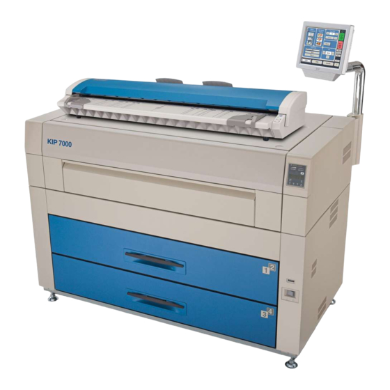
Page 13: Appearance
This is a Touch Screen, and many user operations are available. Top Cover Open to clear the mis-fed paper. It is possible to put KIP 600 Scanner and KIP 2100 Scanner. Manual Table Open to insert a sheet of paper, or to pull the Upper Frame Unit. -
Page 14: Rear View
Connect the cable from the Optional Device. (D-Sub Connector 9 pins: max.12Vdc (Small)) LAN Port Connect the LAN Cable to connect the KIP 7000 to the network. (Do not connect a telephone line.) Breaker It is possible to shut off supplying the AC power. - Page 15 1. 5. 3 Sub Display Panel There is a Sub Display Panel on the top of the printer. Refer to the following page for indicators and key functions. Sub Display Panel Sub Display Panel Status Indicator Toner Remaining Indicator Image Density Indicator TONER REMAIN IMAGE DENSITY Paper Mis-feed Indicator...
- Page 16 Name of part Function Status Indicator Green Orange : Power is not supplied. Lighting Orange : Warming up/printing is prohibited. Flashing Orange : Sleep Mode Flashing Green : Temperature Recovering Mode (Printing is temporarily interrupted to recover the temperature of Fuser Unit.) Lighting Green : Ready/Printing Toner Remaining...
-
Page 17: Indications During Normal Use
1. 6 Indications during Normal Use The Sub Display Panel indicates the following information during normal use. (1) Processing a print The Job Indicator lights green when the printer receives a job. TONER REMAIN IMAGE DENSITY Job Indicator MENU TEST ENTER (2) Image Density level Any of the 4 LEDs of the Image Density Indicator will light according to the density level you... - Page 18 (3) Roll Deck, roll width and roll material currently used Before printing, you can select on the controller or on the scanner which roll media is used for printing. The Sub Display Panel indicates the selected Roll Deck Number and the media width. Sub Display Panel Roll 1 (Front) Roll 2 (Rear)
-
Page 19: Optional Configurations
1. 7 Optional Configurations You can combine the KIP 7000 Digital Printer with optional outer devices. 3 kinds of configurations are shown below but the other finishing devices are also available. Please consult your Service Personnel. (1) In combination with an image Scanner... - Page 20 (3) In combination with an image scanner and controller Controller Scanner KIP 7000 1-14 Part 1 Basic Functions...
-
Page 21: Specifications For The Printing Paper
1. 8 Specifications for the Printing Paper 1. 8. 1 Available Print Size Available print size is as follows. Minimum Maximum Width 11 inches (Roll Paper) 36 inches 210mm (Cut Sheet paper) Length 8.5 inches 6 meters NOTE It is possible to print longer than 6 meters as an option. You can choose either “24m”... -
Page 22: Media Not To Be Used
1. 8. 2 Media not to be used Do not use the following kinds of printing paper. Doing so may damage the printer. Excessively curled Folded Creased Torn Punched 1-16 Part 1 Basic Functions... -
Page 23: Maintaining The Media
Pre-printed Extremely slippery Extremely sticky Extremely thin and soft OHP Film CAUTION Do not use the paper with staple, or do not use such conductive paper as aluminium foil and carbon paper. The above may result in a danger of fire. NOTE (1) Print image may become light if printed on a rough surface of the paper. -
Page 24: Environmental Condition - Correction
High NOTE (1) KIP 7000 is equipped with the Dehumidify Heater. Using it in high humidity environment (65% or higher) is recommended. Refer to [2. 6 Dehumidifying the Roll Media] on page 1-37. (2) “Void of image” and “crease of paper” will occur in case of extremely high or low humidity. - Page 25 NOTE (3) Re-appearance of image (solid black image especially) may occur if you print with a humidified film. When film is installed under the high humidity environment (higher than 60%RH), we also recommend that you turn on the Dehumidify Heater. Normal print Re-appeared image 1-19...
-
Page 26: Chapter 2 Basic Operations 2.1 Turning On The Kip 7000
(4) The outlet must satisfy the following rated power condition. 220V - 240V plus 6% or minus 10%, 50/60Hz, 20A or higher 2) There is a Power Switch (A) on the right-front of KIP 7000. Press “ON” to turn on the KIP 7000. - Page 27 3) There is a Sub Display Panel on the right-front of the printer. The Orange lamp of the Status Indicator lights when the printer is warming up. Status Indicator (Left : Green / Right : Orange) Sub Display Panel TONER REMAIN IMAGE DENSITY MENU TEST...
-
Page 28: Turning Off The Kip 7000
Press this side. CAUTION The KIP 7000 and the User Interface (UI) look to be shut down when you turn off KIP 7000, the IPS inside of KIP 7000 is still operating for approximately 2 minutes after Power Switch operation. -
Page 29: Replacing The Roll Media
2. 3 Replacing the Roll Media NOTE The printer indicates a “Roll Empty Error” by lighting up the Roll Empty Indicator on the Sub Display Panel if the roll media currently used TONER REMAIN IMAGE DENSITY is emptied during printing. Install a new roll media using the following directions. - Page 30 1) When the Roll Empty Indicator lights, check the emptied Roll Deck Number on the Display. Example : Roll Deck Number is “01”. This means the media in the Roll 1 is empty. TONER REMAIN IMAGE DENSITY Roll Deck Number MENU TEST ENTER...
- Page 31 4) Pressing down Lever (C), pull out the Roll Spool (B) from the core of the roll. 5) Loosen the Thumb Screw (D), and slide the Stopper (E) according to the width of the new roll of media. Tighten the Thumb Screw to fix the Stopper at the corresponding size mark. NOTE Align the top of triangle (F) of stopper and the size mark (G).
- Page 32 6) Pressing down the Lever (C), insert the Roll Spool fully into the core until the Stopper (E) touches the roll media. Then, release the Lever (C) to “catch” the roll media with the Roll Spool. NOTE Be careful of the winding direction of roll media. No good Good 1-26...
- Page 33 7) In case you load Roll 1 or Roll 3; Roll 1 Roll 2 Roll 3 Roll 4 Front Rear 7-1) Put back the Roll Spool into the Roll Deck. (Gear side is on the left and Lever side is on the right.) Gear side NOTE When you put back the Roll Spool into the Roll Deck, make sure to fit the collar of the right...
- Page 34 7-2) Rotate the green knob as shown arrow and feed the leading edge of the media between Feeding Rollers. Knob Roll 1 Roll 2 Knob Roll 3 Roll 4 Front Rear 7-3) Close the Roll Deck. 7-4) Press the Initial Cut Key on the User Interface (UI) to cut the leading edge. Remove the paper portion.
- Page 35 8) In case you load Roll 2 or Roll 4; Roll 1 Roll 2 Roll 3 Roll 4 Front Rear 8-1) Put the Roll Spool onto the Operator aid Arm. (Gear side is on the left and Lever side is on the right.) 1-29 Part 1 Basic Functions...
- Page 36 8-2) Move the right one of Operator aid Arms backward and then move the left one similarly. The Roll Spool is set in the proper position Hereby. (Do not move both Operator aid Arms at the same time.) NOTE 1. “Operator aid Arm” was prepared to help the operator when you load the roll paper on the deeper Deck.
- Page 37 8-3) Rotate the green knob as shown arrow and feed the leading edge of the media between Feeding Rollers. Knob Roll 1 Roll 2 Roll 3 Roll 4 Front Rear Knob NOTE When you load the media, rotate the Paper Feeding Roller Knob. Do not feed the media so much because the leading edge may come out from the slit.
-
Page 38: Replacing The Toner Cartridge
The printer will indicate a “Toner Low Error” by Toner Low Indicator lighting the Toner Low Indicator on the Sub Display Panel. Replace the Toner Cartridge with the new cartridge using the following procedure: (Please use the KIP Toner Cartridge.) TONER REMAIN IMAGE DENSITY MENU TEST ENTER 1) Open the Manual Table. - Page 39 3) Push the Joint rightward to release the Toner Cartridge. (The joint is latched.) Joint 4) Press and hold the Lever to the left, and then rotate the Toner Cartridge (not the Cap of Cartridge) as shown arrow in order to close the opening. Approximately 2 rotations will be enough to close the opening, but rotate the Toner Cartridge until it stops completely.
- Page 40 6) Shake a new Toner Cartridge several times right and left to make the toner smooth. 7) Insert the far left Collar of the Toner Cartridge into the slot firmly with pressing the Lever to the left. (Please direct the opening of the Toner Cartridge downward at this time.) 8) Pull the Toner Cartridge rightward a little, and insert the swelling in the slot.
- Page 41 9) Rotate the Toner Cartridge to the arrow direction at least 90 degrees. (The new Toner Cartridge is closed firmly so as not to lose the toner during the transportation) NOTE Even if the Joint is not fit to the Toner Cartridge, when you turn on the power, it is automatically fit properly.
-
Page 42: Setting The Cut Sheet Paper
2. 5 Setting the Cut Sheet Paper 1) Open the Manual Table. Manual Table Size Mark 2) There are several kinds of size mark on the Manual Table. Put the cut sheet paper on the table along with the concerning size mark, and then insert it into the Bypass Feeder along with the size mark. -
Page 43: Dehumidifying The Roll Media
2. 6 Dehumidifying the Roll Media If the roll paper is extremely humid, it may cause poor prints. You will experience most likely “creasing” and “voids”. Normal Print Creasing If the media is humidified ; Normal Print Voids If the media is humidified ; NOTE Re-appearance of image (especially solid black image) may occur if you print with a humidified film. - Page 44 NOTE (1) There are several dehumidifying settings which can be set by the service personnel. When these setting determine, the dehumidifier functions. With any setting, the printer must be plugged in and the switch noted above must be in the “ON” position. Call your service personnel if you would like to change the switch setting.
-
Page 45: Changing The Density Level
Chapter 3 Operations for Useful Functions 3. 1 Changing the Density Level If you would like to make the image darker or lighter, you will change the density level on the scanner or controller. After specifying the density level on the scanner or controller, it is also possible to compensate the image density on the printer, if needed. -
Page 46: User Mode
3. 2 User Mode To enter the User Mode Press and hold the [Menu] key for more than 3 seconds. Then User Mode Number and its contents are shown on the Display. TONER REMAIN IMAGE DENSITY User Mode Number Contents MENU TEST ENTER... -
Page 47: User Mode 0: (Reserved)
3. 2. 1 User Mode 0: (Reserved) Keep this mode always “oFF”. (Do not change this setting.) 1-41 Part 1 Basic Functions... -
Page 48: User Mode 1: Image Enhancement Setting Mode
3. 2. 2 User Mode 1: Image Enhancement Setting Mode A weak image can be emphasized by such functions as the Dot Enhancement Level and the Smoothing Function so that it looks clearer. Reference (1) An isolated dot image can be emphasized by the Dot Enhance Level. (Dot Enhance Level does not affect the compacted dots.) Isolated dots are emphasized. - Page 49 1) Select User Mode 1 “U1.” by pressing [ ] or [ ] key. TONER REMAIN IMAGE DENSITY Applied to the prints from controller MENU TEST ENTER The setting value consists of 2 digits. The left value is not used. The right one is applied to the print from controller.
-
Page 50: User Mode 2: Auto Power Off Timer Setting Mode
3. 2. 3 User Mode 2: Auto Power Off Timer Setting Mode This mode allows you to set Auto Power Off Timer. Reference The Auto Power Off is the function that the Power Switch turns OFF automatically if the printer makes no printing (copying) operation for the time decided in the User Mode 2. (As for turning on the printer, press “ON”... -
Page 51: User Mode 3: Auto Power Off Setting Mode
3. 2. 4 User Mode 3: Auto Power Off Setting Mode It is possible to select whether or not the Auto Power Off works. Reference The Auto Power Off is the function that the Power Switch turns OFF automatically if the printer makes no printing (copying) operation for the time decided in the User Mode 2. -
Page 52: User Mode 4: Cold Sleep Timer Setting Mode
It can save more power than Warm Sleep Mode. The temperature of the heater unit is about 150 degrees Centigrade when the KIP 7000 is ready. But if no print job or copy job is sent for a long time, it is best for saving the power to stop supplying the power to the heater unit completely. -
Page 53: User Mode 5: Cold Sleep Setting Mode
It can save more power than Warm Sleep Mode. The temperature of the heater unit is about 150 degrees Centigrade when the KIP 7000 is ready. But if no print job or copy job is sent for a long time, it is best for saving the power to stop supplying the power to the heater unit completely. -
Page 54: User Mode 6: Warm Sleep Timer Setting Mode
The temperature of the heater unit is about 150 degrees Centigrade when the KIP 7000 is ready. But if no print job or copy job is sent for a long time, it is better for saving the power to fall down the temperature of heater. -
Page 55: User Mode 7: Warm Sleep Setting Mode
The temperature of the heater unit is about 150 degrees Centigrade when the KIP 7000 is ready. But if no print job or copy job is sent for a long time, it is better for saving the power to fall down the temperature of heater. -
Page 56: User Mode 8: (Reserved)
3. 2. 9 User Mode 8: (Reserved) Keep this mode always “oFF”. (Do not change this setting.) 1-50 Part 1 Basic Functions... -
Page 57: User Mode 9: L/L Environment Setting Mode
3. 2.10 User Mode 9: L/L Environment Setting Mode It is possible to select whether or not the L/L Environment Setting Mode should work. Reference “Crease of paper” or “Defective fusing” may occur when a large paper (wider than 30”) is used in the low temperature and low humidity environment (It is called L/L Environment). - Page 58 2) Select either “on” or “oFF” according to the necessity by pressing [ENTER] key. TONER REMAIN IMAGE DENSITY MENU TEST ENTER 1-52 Part 1 Basic Functions...
-
Page 59: User Mode A: H/H Environment Setting Mode
3. 2.11 User Mode A: H/H Environment Setting Mode It is possible to select whether or not the H/H Environment Setting Mode should work. Reference “Crease of paper” or “Foggy background” may occur when a large paper (wider than 30”) is installed to the Roll 2 or Roll 4 in the high temperature and high humidity environment (It is called H/H Environment). - Page 60 1) Select User Mode A “UA.” by pressing [ ] or [ ] key. TONER REMAIN IMAGE DENSITY MENU TEST ENTER U A. o n : H/H Environment Setting works. U A. o F F : H/H Environment Setting does not work. (Normal operation) 2) Select either “on”...
-
Page 61: User Mode B: High Coverage Setting Mode
3. 2.12 User Mode b: High Coverage Setting Mode It is possible to select whether or not the High Coverage Setting Mode should work. High Coverage Setting Mode will be effective if the image density looks lighter when you print some image pattern which consists of many data. -
Page 62: User Mode C: (Reserved)
3. 2.13 User Mode C: (Reserved) Keep this mode always “oFF”. (Do not change this setting.) 1-56 Part 1 Basic Functions... -
Page 63: User Mode D: (Reserved)
3. 2.14 User Mode d: (Reserved) Keep this mode always “oFF”. (Do not change this setting.) 1-57 Part 1 Basic Functions... -
Page 64: Chapter 4 Error Indications And Treatments
Chapter 4 Error Indications and Treatments 4. 1 Paper Mis-feed Errors If the Paper Mis-feed occurs, the Paper Mis-feed Indicator on the Sub Display Panel lights to inform you of the error. The Sub Display Panel also indicates the Paper Mis-feed Code ( J-XX ) to let you know where the paper is mis-fed. - Page 65 NOTE (1) Carefully remove the mis-fed paper so as not to harm your hand by cutting with the paper edge. (2) Take off a necklace, a bracelet and a wristwatch before removing the mis-fed paper. You may be burnt or get an electric shock if such a metal accessory touches the inside of the printer.
-
Page 66: Paper Mis-Feed In The Roll Deck Section (J-01, J-02, J-03, J-04)
4. 1. 1 Paper Mis-feed in the Roll Deck Section (J-01, J-02, J-03, J-04) When the Paper Mis-feed occurs in the Roll Deck, the Sub Display Panel indicates any of “J-01”, “J-02”, “J-03” and “J-04”. J-01 : In the Roll 1 J-02 : In the Roll 2 J-03 : In the Roll 3 J-04 : In the Roll 4... - Page 67 2) If the leading edge of the media is torn or folded, cut it off. 3) Set the roll media correctly. NOTE When you put back the Roll Spool into the Roll Deck, make sure to fit the collar of the right side of the Roll Spool into the proper position.
-
Page 68: Paper Mis-Feed In The Manual Feeder Section (J-05)
4. 1. 2 Paper Mis-feed in the Manual Feeder Section (J-05) When the paper mis-feed occurs in the Manual Feeder, the Sub Display Panel indicates “J-05”. TONER REMAIN IMAGE DENSITY J-05 Roll 1 Roll 2 MENU TEST Roll 3 Roll 4 ENTER Front Rear... -
Page 69: Paper Mis-Feed In The Paper Feeder Section (J-10, J-11, J-12)
4. 1. 3 Paper Mis-feed in the Paper Feed Section (J-10, J-11, J-12) When the Paper Mis-feed occurs in the Paper Feed Section, Sub Display Panel indicates any of “J-10”, “J-11” and “J-12” according to the position of mis-feed. J-10 : Front area J-11 : Middle area J-12 : Rear area TONER REMAIN... - Page 70 Clear the Paper Mis-feed using the following procedure: 1) Press the Initial Cut Key on the User Interface (UI). NOTE The roll paper is cut hereby even if it has not been cut at the time of mis-feed. (1) Once you make the Cutter work by pressing the Initial Cut Key on the User Interface (UI), it will not work again even if you press the Cut key more times.
-
Page 71: Paper Mis-Feed In Fuser Section (J-13, J-14)
4. 1. 4 Paper Mis-feed in the Fuser Section (J-13, J-14) When the Paper Mis-feed occurs in the Fuser Section, the Sub Display Panel indicates either of “J-13” and “J-14”. J-13, J-14 TONER REMAIN IMAGE DENSITY MENU TEST ENTER Roll 1 Roll 2 Roll 3 Roll 4... - Page 72 Clear the Paper Mis-feed using the following procedure: 1) Press the Initial Cut Key on the User Interface (UI). NOTE The roll paper is cut hereby even if it has not been cut at the time of mis-feed. (1) Once you make the Cutter work by pressing the Initial Cut Key on the User Interface (UI), it will not work again even if you press the Cut key more times.
- Page 73 4) Open the Manual Table. 5) Pull out the Upper Frame Unit to your side holding both handles. Manual Table Handles 6) Pull up both knobs, and then push the Top Cover to rear side. Top Cover Knob 7) Remove the mis-fed paper. 8) Close the Top Cover and the Upper Frame Unit.
-
Page 74: Paper Mis-Feed In Outer Device (J-21, J-22)
4. 1. 5 Paper Mis-feed in Outer Device (J-21, J-22) When the Paper Mis-feed occurs in Outer Device, the Sub Display Panel indicates either of “J-21” or “J-22”. TONER REMAIN IMAGE DENSITY TONER REMAIN IMAGE DENSITY MENU TEST MENU TEST ENTER ENTER Clear the mis-feed using the following procedure:... -
Page 75: Open Cover Errors
4. 2 Open Cover Errors The Sub Display Panel will indicate the error code (U-XX) if there are any open decks or open covers. Close each deck (or cover) as it is impossible to print, if this error exists. 4. 2. 1 Roll Deck Open (U-01, U-02) The corresponding Roll Deck is opened when the Sub Display Panel indicates “U-01”... - Page 76 NOTE This error code will be indicated if the Roll Deck is not locked correctly, although it may look closed. Open and close the Roll Deck again, pushing until locked. Ensure both sides of the roll deck are in their correct position. The Roll Deck is firmly locked.
-
Page 77: Upper Frame Unit / Top Cover Open (U-05)
4. 2. 2 Upper Frame Unit / Top Cover Open (U-05) When either the Upper Frame Unit or the Top Cover is opened the Sub Display Panel indicates “U-05”. TONER REMAIN IMAGE DENSITY MENU TEST ENTER Check if the Upper Frame Unit and the Top Cover are closed firmly. Top Cover Upper Frame Unit 1-71... -
Page 78: Exit Cover Open (U-06)
4. 2. 3 Exit Cover Open (U-06) When the Exit Cover is opened, the Sub Display Panel indicates “U-06”. TONER REMAIN IMAGE DENSITY MENU TEST ENTER Close the Exit Cover. Exit Cover 1-72 Part 1 Basic Functions... -
Page 79: Other Errors
4. 3 Other Errors 4. 3. 1 Toner Low The machine indicates a “Toner Low” by lighting the Toner Low Indicator on the Sub Display Panel. Toner Cartridge replacement is required. Refer to [2.4 Replacing the Toner Cartridge] on page 1-32. Toner Low Indicator TONER REMAIN IMAGE DENSITY... -
Page 80: Roll Empty
4. 3. 2 Roll Empty The machine indicates a “Roll Empty” by lighting the Roll Empty Indicator on the Sub Display Panel if the roll media currently in use is consumed during printing. Installation of a new roll is required. Refer to [2.3 Replacing the Roll Media] on page 1-23. -
Page 81: No Manual Paper (P.e.)
4. 3. 3 No Manual Paper (P.E.) The machine indicates “P.E.-XX” on the Sub Display Panel when the cut sheet paper is not set on the Manual Feeder. “XX” means the required paper size. Set the indicated size of paper. Refer to [2.5 Setting the Cut Sheet Paper] on page 1-36. -
Page 82: Call Service Errors
4. 4 Call Service Errors You will note one of the following Error Codes on the Operation panel if the machine has the fatal error. It is impossible for the user to cure these errors to resolve these issues. PLEASE CALL YOUR TRAINED SERVICE PERSONNEL TO RESOLVE THESE ERRORS. Error Code Name of the error E - 01...
Need help?
Do you have a question about the 7000 and is the answer not in the manual?
Questions and answers