
Related Manuals for Mellanox Technologies Spectrum SN2740


Summary of Contents for Mellanox Technologies Spectrum SN2740
- Page 1 Mellanox Spectrum™ 1U Switch Systems Hardware User Manual Models: SN2700, SN2740, SN2410, SN2100 and SN2010 Rev 2.2 Mellanox Technologies www.mellanox.com...
- Page 2 NOTE: THIS HARDWARE, SOFTWARE OR TEST SUITE PRODUCT (“PRODUCT (S)”) AND ITS RELATED DOCUMENTATION ARE PROVIDED BY MELLANOX TECHNOLOGIES “AS -IS” WITH ALL FAULTS OF ANY KIND AND SOLELY FOR THE PURPOSE OF AIDING THE CUSTOMER IN TESTING APPLICATIONS THAT USE THE PRODUCTS IN DESIGNATED SOLUTIONS.
-
Page 3: Table Of Contents
3.2 LEDs ............68 Rev 2.2 Mellanox Technologies... - Page 4 6.5 SN2010 Series ..........89 Rev 2.2 Mellanox Technologies...
- Page 5 Table 32: QSFP Pin Description 21-38..........93 Rev 2.2 Mellanox Technologies...
- Page 6 Table 33: SFP Pin Description ..........94 Rev 2.2 Mellanox Technologies...
- Page 7 Figure 34: Rack Rail Kit Parts ............44 Rev 2.2 Mellanox Technologies...
- Page 8 Figure 70: Fan Status LED in SN2100 ........... 72 Rev 2.2 Mellanox Technologies...
- Page 9 Figure 87: RJ45 to DB9 Harness Pinout ..........96 Rev 2.2 Mellanox Technologies...
-
Page 10: Table 1: Revision History Table
“Side by Side Mounting for SN2100/SN2010 Rail Kit” May 2016 Added SX1012 to the following sections: • “Introduction to Mellanox SN2000 Spectrum™ Ethernet Switch Systems” • “Installation” • “Interfaces” • “Specifications” • “Accessory and Replacement Parts” Rev 2.2 Mellanox Technologies... - Page 11 “Introduction to Mellanox SN2000 Spectrum™ Ethernet Switch Systems” • “Software Management” • “Troubleshooting Instructions” • “Specifications” • “Accessory and Replacement Parts” Added: • Taiwan BSMI Class A Statement in Safety Warnings December Added SN2410 2015 August 2015 Initial revision Rev 2.2 Mellanox Technologies...
-
Page 12: Table 2: References
Quick Start Guide Conventions The following icons are used throughout this document to indicate information that is important to the user. This icon makes recommendations to the user. This icon indicates information that is helpful to the user. Rev 2.2 Mellanox Technologies... - Page 13 This icon indicates a situation that can potentially cause damage to hardware or software. This icon indicates a situation that can potentially cause personal injury. This icon indicates a situation that can potentially cause personal injury. Rev 2.2 Mellanox Technologies...
-
Page 14: Chapter 1 Introduction To Mellanox Sn2000 Spectrum™ Ethernet Switch Systems
100GbE and the 40GbE versions) are offered, in addition, with Cumulus Linux support, as an alternative operating system. For a full list of all available ordering options, see “Ordering Infor- mation”. Figure 1: SN2700 Front Side View Rev 2.2 Mellanox Technologies... -
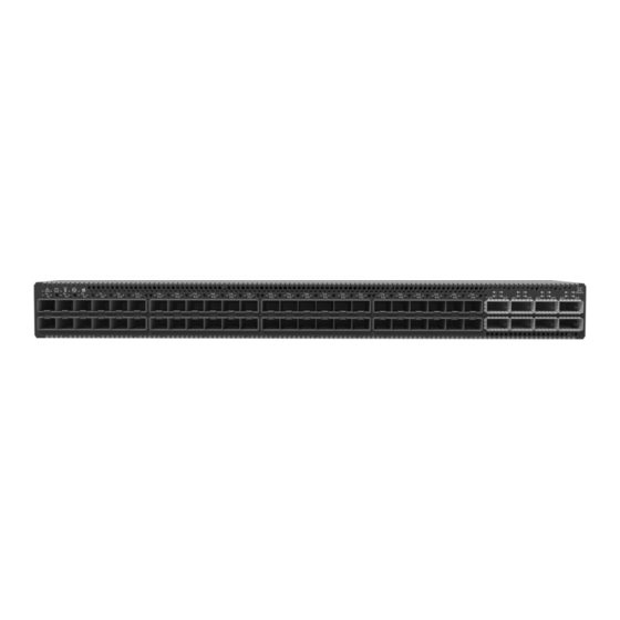
Page 15: Figure 2: Sn2740 Front Side View
Figure 3: SN2410 Front Side View Figure 4: SN2100 Front Side View Figure 5: SN2010 Front Side View Figure 6: SN2700 and SN2410 Rear Side View Figure 7: SN2740 Rear Side View Figure 8: SN2100 Rear Side View Rev 2.2 Mellanox Technologies... -
Page 16: Speed And Switching
Rear (2 ports) Rear 2 units 4 units SN2100 Front (mini Front (1 port) Front 2 units (non- 4 units (non- USB) replaceable) replaceable) SN2010 Front Front (1 port) Front 2 units (non- 4 units (non- replaceable) replaceable) Rev 2.2 Mellanox Technologies... -
Page 17: Features
In the main menu, click on Products--> Ethernet Switch Systems, and select the desired product page. Certifications The list of certifications (such as EMC, Safety and others) per system for different regions of the world is located on the Mellanox website at: http://www.mellanox.com/page/environmental_compliance Rev 2.2 Mellanox Technologies... -
Page 18: Ordering Information
Spectrum(TM) 100GbE 1U switch w/Cumulus Linux, 32 QSFP28 ports, 2 AC PSUs, x86 2core, standard depth, C2P airflow, Rail Kit, RoHS6, (Cumulus License Key is required, provided at no cost with purchase of support SKU SUP-SN2000-XX) Rev 2.2 Mellanox Technologies... - Page 19 Rail Kit, (Cumulus License Key is required) MSN2410-CB2RO Spectrum(TM) based 25GbE/100GbE 1U Open Ethernet switch with ONIE, 48 SFP28 ports, 8 QSFP28 ports, 2 power supplies (AC), x86 dual core, Short depth, C2P airflow, Rail Kit, RoHS6 Rev 2.2 Mellanox Technologies...
- Page 20 C2P airflow, Rail Kit must be purchased separately, RoHS6 MSN2100-CB2RC Spectrum(TM) 100GbE 1U switch w/Cumulus Linux, 16 QSFP28 ports,2 AC PSUs,x86 2core, short depth, C2P airflow, Rails 2 be pur- chased separately, (Cumulus License Key is required) Rev 2.2 Mellanox Technologies...
- Page 21 RoHS6 MSN2010-CB2RC Spectrum(TM) based 25GbE/100GbE 1U Open Ethernet switch with Cumulus Linux, 18 SFP28 and 4 QSFP28 ports, 2 power supplies (AC), x86 Atom CPU, short depth, C2P airflow, Rail Kit must be purchased separately, RoHS6 Rev 2.2 Mellanox Technologies...
-
Page 22: Chapter 2 Installation
134. • For Safety Warnings in Italian, see Section E.12, “Avvertenze di sicurezza per l’installazione (Italian),” on page 138. • For Safety Warnings in Turkish see Section E.13, “Montaj Güvenlik Uyarıları (Turk- ish),” on page 142. Rev 2.2 Mellanox Technologies... -
Page 23: System Installation And Initialization
SN2010 systems, the fan units are non-replaceable. Mellanox systems are offered with two air flow patterns: • Power (rear) side inlet to connector side outlet - marked with blue power supplies/fans- FRUs’ handles, as shown in Figure Rev 2.2 Mellanox Technologies... -
Page 24: Table 6: Air Flow Color Legend
Red latches are placed on the power inlet side. Ending with Power side inlet to connector side outlet. “-F” Blue latches are placed on the power inlet side. Figure 10: Air Flow Direction Marking - Power Side Inlet to Connector Side Outlet Rev 2.2 Mellanox Technologies... -
Page 25: Package Contents
(can be used with SN2700 only), see Section 2.5.2. The SN2100/SN2010 system is sold without a rail kit. A designated rail kit can be purchased sep- arately. For installation instructions, see Section 2.5.4. Rev 2.2 Mellanox Technologies... -
Page 26: Static Rail Kit For Sn2700
• 4x Phillips100 DEG F.H TYPE-I ST.ST 6-32 X 1/4 screws with a round patch (E) ¹ Other threads are available by special order: M5, 10-32, 12-24 ² G-type cage-nut is available by special order. Figure 12: Rack Rail Kit Parts Rev 2.2 Mellanox Technologies... - Page 27 2) will determine the system’s adjustable side. The system’s part to which the brackets are attached will be adjacent to the cabinet. • The FRU side is extractable. Mounting the rack brackets inverted to the FRU side (Option 2) will allow you to slide the FRUs, in and out. Rev 2.2 Mellanox Technologies...
-
Page 28: Figure 13: Installation Options
Secure the chassis in the rails by screwing 2 flat head Phillips screws (E) in the designated Step 2. points with a torque of 1.5±0.2 Nm. See Figure Rev 2.2 Mellanox Technologies... -
Page 29: Figure 14: Attaching The Rails To The Chassis
Figure 15: Attaching the Brackets to the Chassis Install 8 cage nuts in the desired slots of the rack: 4 cage nuts in the non-extractable side (in Step 4. the top and bottom holes only) and 4 cage nuts in the extractable side. Rev 2.2 Mellanox Technologies... -
Page 30: Figure 16: Installing The Cage Nuts
Slide the two blades into the left and right rails, and adjust them to fit your rack's depth. Use Step 6. four M6 screws (D) to fix the blades into the rack. Do not tighten the screws yet. Rev 2.2 Mellanox Technologies... -
Page 31: Telescopic Rail Kit For Sn2700
2.5.2 Telescopic Rail Kit for SN2700 The Telescopic rail kit is not included in the system’s package, and can be purchased separately. There are two installation kit options: • Standard depth systems should be mounted using the standard rail kit. Rev 2.2 Mellanox Technologies... -
Page 32: Table 8: Installation Kit
• 2x Phillips100 DEG F.H TYPE-I ST.ST 6-32 X 1/4 screw with a round patch (F) ¹ Other threads are available by special order: M5, 10-32, 12-24 ² G-type cage-nut is available by special order. The rails must be separated prior to the installation procedure. See Figure Rev 2.2 Mellanox Technologies... -
Page 33: Figure 19: Rack Rail Kit Parts
Installation Figure 19: Rack Rail Kit Parts Rev 2.2 Mellanox Technologies... -
Page 34: Figure 20: Rails Separation
Mount both of the outer rails (C+D) into the rack (as illustrated in Figure 22), and use 8 Step 2. standard pan-head screws (E) to fix them to the rack. Do not tighten the screws yet. Rev 2.2 Mellanox Technologies... -
Page 35: Figure 22: Mounting The Outer Rails Into The Rack
1.5±0.2 Nm. Figure 24: Securing the Chassis in the Inner Rails Slide the switch into the rack by carefully pushing the inner rails into the outer rails installed Step 6. on the rack. Rev 2.2 Mellanox Technologies... -
Page 36: Figure 25: Sliding The Switch Into The Rack
Unscrew the two M6 screws securing the front of the inner rails’ ears to the outer rails and Step 2. to the rack. Pull the unit out until braking is felt. For safety purposes, the locking mechanism will not Step 3. allow a complete removal of the unit at this stage. Rev 2.2 Mellanox Technologies... -
Page 37: Figure 26: Pulling The Unit Outwards
Figure 26: Pulling the Unit Outwards Press on the locking spring (appears in red in Figure 27) on both sides simultaneously, and Step 4. continue pulling the unit towards you until it is fully removed. Figure 27: Locking Mechanism Rev 2.2 Mellanox Technologies... -
Page 38: Static Rail Kit For Sn2740 And Sn2410
• 8x M6 Standard cage nuts¹ ² and 8x M6 Standard pan-head Phillips screws¹ (C) • 4x Phillips100 DEG F.H TYPE-I ST.ST 6-32 X 1/4 screw with around patch (D). ¹ Other threads are available by special order: M5, 10-32, 12-24 ² G-type cage-nut is available by special order. Rev 2.2 Mellanox Technologies... -
Page 39: Figure 28: Rack Rail Kit Parts
3.5" (8.9 cm), by optional placement of the system’s rails. • The FRU side is extractable. Mounting the rack blades inverted to the FRU side (Option 2) will allow you to slide the FRUs, in and out. Rev 2.2 Mellanox Technologies... -
Page 40: Figure 29: Installation Options
Install 8 cage nuts (C) in the desired slots of the rack: 4 cage nuts in the non-extractable side Step 2. and 4 cage nuts in the extractable side. Note that while each rack U (unit) consists of three Rev 2.2 Mellanox Technologies... -
Page 41: Figure 31: Installing The Cage Nuts
Slide the two blades into the left and right rails, and adjust them to fit your rack's depth. Use Step 4. four M6 screws (D) to fix the blades into the rack. Do not tighten the screws yet. See Figure Rev 2.2 Mellanox Technologies... -
Page 42: Side By Side Mounting For Sn2100/Sn2010 Rail Kit
A designated rail kit for the SN2100/SN2010 systems can be purchased separately. This section is relevant to short-depth systems that allow such form of installation only. At least two people are required to safely mount the system in the rack. Rev 2.2 Mellanox Technologies... -
Page 43: Table 10: Installation Kit
• 10 (+2 spare units) M6 pan head screws (G) • 10 (+2 spare units) M6 spring washers (H) • 10 (+2 spare units) M6 spring steel cage nuts (I) • 6 (+2 spare units) cable-ties (J) Rev 2.2 Mellanox Technologies... -
Page 44: Figure 34: Rack Rail Kit Parts
• You may choose to install your system in the right or in the left part of the metal frame. The following instructions apply to installation in the right part. For installation in the Rev 2.2 Mellanox Technologies... -
Page 45: Figure 35: Coupling The Cables With Cable-Ties
Figure 35: Coupling the Cables with Cable-ties Figure 36: Coupled Cables - Rear View Place the coupled cables in the designated area within the right flat blade (the blade with 7 Step 3. screw holes) as shown in Figure Rev 2.2 Mellanox Technologies... -
Page 46: Figure 37: Cables Within The Rail
While holding the cables stably together in the blade’s rail with one hand, use your other Step 4. hand to secure the blades to the chassis. Screw the right blade with eight 4-40 flathead screws, and the left blade with seven 4-40 flathead screws. The recommended torque is 0.49-0.54 Nm. Rev 2.2 Mellanox Technologies... -
Page 47: Figure 38: Attach The Blades To The System
Installation Figure 38: Attach the Blades to the System Figure 39: Attached Rail with Threaded Cables - Top View Slide the two frame slides into the dedicated rails in the metal frame. See Figure Step 5. Rev 2.2 Mellanox Technologies... -
Page 48: Figure 40: Sliding The Frame Sliders Into The Rails
Attach the frame to the rack by using ten spacer cage nuts, and screw ten M6 pan head Step 7. screws - four in the front part of the rack, and 6 in its rear part. The recommended torque is 6.55-7.35 Nm. See Figure 41. Place the frame in the cabinet. Step 8. Rev 2.2 Mellanox Technologies... -
Page 49: Figure 42: Attaching The Frame To The Rack
Tighten the capture nuts to secure the system in the frame. The recommended torque on the Step 10. right screw is 3.0-3.36 Nm while on the left screw recommended torque is 0.89-0.98 Nm. Figure 43: Sliding the System’s Blades in the Rails Rev 2.2 Mellanox Technologies... -
Page 50: Cable Installation
Greater insertion force may cause damage to the cable or to the cage. The SN2410 system includes ports of different types. Figure 43 below does not apply to the SFP28 ports. See Figure Figure 44: SN2700, SN2100 and SN2010 QSFP Cable Orientation Rev 2.2 Mellanox Technologies... -
Page 51: Splitter (Breakout) Cables And Adapters
A 100GbE port can be split to two 50GbE ports, or to four (or less) 25GbE ports, using a Mella- nox splitter cable. Splitting a 100GbE QSFP28 port to 4 separate 25GbE ports (using a splitter cable) disables (unmaps) the 100GbE port below it. See Figure 49,“SN2700 and SN2740 Splitting Options”. Rev 2.2 Mellanox Technologies... -
Page 52: Figure 48: Splitter (Breakout Or Fanout) Cables
For more details, see Layer 1 and Switch sudo systemctl restart switchd Port Attributes in the Cumulus Linux User Guide. Figure 48: Splitter (Breakout or Fanout) Cables Rev 2.2 Mellanox Technologies... -
Page 53: Figure 49: Sn2700 And Sn2740 Splitting Options
The top QSFP28 ports - 49,51,53,55 (green) are splittable to 4 SFP28 ports each. All QSFP28 ports can be split into two QSFP28 ports. The bottom QSFP28 ports - 50,52,54,56 (gray) are blocked when the upper ports are in split mode. Rev 2.2 Mellanox Technologies... -
Page 54: Initial Power On
Check all boards, power supplies, and fan tray modules for proper insertion before plugging in a power cable. Plug in the first power cable. Step 1. Plug in the second power cable. Step 2. Wait for the System Status LED to turn green. Step 3. Rev 2.2 Mellanox Technologies... -
Page 55: Figure 52: System Status Leds 5 Minutes After Power On In Sn2700
Figure 52: System Status LEDs 5 Minutes After Power On in SN2700 Figure 53: System Status LEDs 5 Minutes After Power On in SN2740 Figure 54: System Status LEDs 5 Minutes After Power On in SN 2410 Rev 2.2 Mellanox Technologies... -
Page 56: System Bring-Up
Pour isoler completement le Netzstecker aller Netzteile module en cause, Il faut zu entfernen de’brancher toutes les alimen- tations stabilise’es. System Bring-Up For bring-up of a switch system with Onyx (MLNX-OS) operating system installed, refer to Sec- tion 2.8.1. Rev 2.2 Mellanox Technologies... -
Page 57: Configuring Network Attributes Using Onyx (Mlnx-Os)
Type ‘y’ and then press for initial configuration? yes <Enter>. Step 1: Hostname? [switch-1] If you wish to accept the default hostname, press <Enter>. Other- wise, type a different hostname and press <Enter>. Rev 2.2 Mellanox Technologies... - Page 58 To change an answer, enter the step number to return to or hit Note: <enter> to save changes and To re-run the configuration wizard, run the command “configura- exit. tion jump-start” in Config mode. Choice: <Enter> Configuration changes saved. Rev 2.2 Mellanox Technologies...
-
Page 59: Table 13: Configuration Wizard Session - Static Ip Configuration
To change an answer, enter the step number to return to. Otherwise hit <enter> to save changes and exit. Choice: Configuration changes saved. To return to the wizard from the CLI, enter the “configuration jump-start” command from configure mode. Launching CLI... > Rev 2.2 Mellanox Technologies... - Page 60 Check the software version embedded in your system, using the command ‘show version’. Step 6. Compare this version to the latest version that can be retrieved from Mellanox support site. To upgrade software, please refer to the Onyx (MLNX-OS) User Manual. Rev 2.2 Mellanox Technologies...
-
Page 61: Configuring Network Attributes Using Cumulus Linux
2.8.2.1 Remote Connection with Cumulus Linux Cumulus Linux uses the OpenSSH package to provide SSH functionality. To securely access a Cumulus Linux switch remotely, please follow the instructions on the SSH for Remote Access page in the Cumulus Linux User Guide. Rev 2.2 Mellanox Technologies... -
Page 62: Fru Replacements
Grasping the handle with your hand, push the latch release with your thumb while pulling Step 2. the handle outward. As the power supply unit unseats, the power supply unit status LEDs will turn off. Remove the power supply unit. Step 3. Rev 2.2 Mellanox Technologies... -
Page 63: Fans
Make sure that the fans have the air flow that matches the model number. An air flow opposite to the system design will cause the system to operate at a higher (less than optimal) temperature. For power supply unit air flow direction, refer to Section 2.3 on page Rev 2.2 Mellanox Technologies... -
Page 64: Figure 59: Fan Module Latches
The green Fan Status LED should light. If not, extract the fan unit and reinsert it. After system two unsuccessful attempts to install the fan unit, power off the before attempt- ing any system debug. Figure 59: Fan Module Latches Rev 2.2 Mellanox Technologies... -
Page 65: Chapter 3 Interfaces
1, 2, 31, 32 SN2410 2.5W 1,2,47,48 49, 50, 55, 56 4.5W SN2100 1, 2, 15, 16 4.5W SN2010 19,20,21,22 4.5W a. 4.5W high power modules are supported on Onyx (MLNX-OS) from version 3.6.3004 onwards. b. SFP28 ports Rev 2.2 Mellanox Technologies... -
Page 66: Speed
10GbE to 100GbE (for more details, see “Specifications”). To change the port speed configuration, use the command “speed” under interface configuration mode. Refer to the Onyx (MLNX-OS) User Manual for instructions on port speed re-configuration. Rev 2.2 Mellanox Technologies... -
Page 67: Rs232 (Console)
To view the full matrix of the USB configuration options, refer to Table 4, “Management Inter- faces, PSUs and Fans”. Do not use excessive force when inserting or extracting the USB disk to and from the connector. Rev 2.2 Mellanox Technologies... -
Page 68: Reset Button
Conditions System Status Shows the health of the system. Green/Flashing green when boot- Fan Status LED Shows the health of the fans. Green Power supply units Shows the health of the power supply units. Green LEDs Rev 2.2 Mellanox Technologies... -
Page 69: Figure 62: System Status Leds - Front And Rear Sides In Sn2700
Figure 62: System Status LEDs - Front and Rear Sides in SN2700 Both of these LEDs in the red ovals show the system’s status. Figure 63: System Status LEDs - Front Side in SN2740 The LED in the red oval shows the system’s status. Rev 2.2 Mellanox Technologies... -
Page 70: Figure 64: System Status Leds - Front And Rear Sides In Sn2410
Both of the System Status LEDs (front and back, if exist) supply identical information. It may take up to five minutes to turn on the system. If the System Status LED shows red after five minutes, unplug the system and call your Mellanox representative for assistance. Rev 2.2 Mellanox Technologies... -
Page 71: Table 16: System Status Led Assignments
Figure 67: Fan Status LED in SN2700 - Front and Rear Sides Both of these LEDs in the red ovals show the fans’ status. Figure 68: System Status LEDs - Front Side in SN2740 The LED in the red oval shows the fans’ status. Rev 2.2 Mellanox Technologies... -
Page 72: Table 17: Fan Status Front Led Assignments
Table 17 - Fan Status Front LED Assignments Description Action Required Behavior Solid All fans are up and running. Green Solid Red Error, one or more fans are not operating prop- The faulty FRUs should be replaced. erly. System boot Rev 2.2 Mellanox Technologies... -
Page 73: Table 18: Fan Status Rear Led Assignments (One Led Per Fan)
In case the power supply is an FRU, a second power supply unit can be added to support hot-swap ability. Each power supply unit has a single 2 color LED on the right side of the unit, that indicates the status of the unit. Rev 2.2 Mellanox Technologies... -
Page 74: Table 20: Power Supply Unit Status Front Led Assignments For Sn2100/Sn2010
Solid Green Power supply is running normally. Solid Red PSU is faulty or disconnected Make sure the AC cable is plugged in and active. If the problem resumes, the PSU might be faulty. PSU not present Rev 2.2 Mellanox Technologies... -
Page 75: Table 21: Power Supply Unit Status Rear Led Assignments
(config) # led MGMT uid off 3.2.1.5 Bad Port LED The Bad Port LED indicator is used to indicate symbol errors in one or more system ports. Table 22 shows the bad port status LED assignment. Rev 2.2 Mellanox Technologies... -
Page 76: Table 22: Bad Port Led Assignments
Replace the cable on these ports. • Bad cable • Bad connection • Bad connector 3.2.1.6 Port LEDs Figure 75: SN2740 Port LEDs Figure 76: SN2410 SFP28 Port LEDs Figure 77: SN2410 QSFP28 Port LEDs Figure 78: SN2010 QSFP Port LEDs Rev 2.2 Mellanox Technologies... -
Page 77: Figure 79: Sn201Port Leds
LEDs (3 and 4) will light green for the lower port. • If the ports run at a 25GbE/10GbE speed each, all LEDs may light green, according to the selected lane. Rev 2.2 Mellanox Technologies... -
Page 78: Inventory Information
In some systems, there is no pull-out tab, and the information is provided on labels in sev- eral locations. Figure 81: SN2700 Pull-out Tab Rev 2.2 Mellanox Technologies... -
Page 79: Figure 82: Sn2740 Inventory Information Illustration
Interfaces Figure 82: SN2740 Inventory Information Illustration Rev 2.2 Mellanox Technologies... -
Page 80: Figure 83: Sn2410 Inventory Information Illustration
Interfaces Figure 83: SN2410 Inventory Information Illustration Figure 84: SN2100 Pull-out Tab Rev 2.2 Mellanox Technologies... -
Page 81: Figure 85: Sn2010 Pull-Out Tab
Interfaces Figure 85: SN2010 Pull-out Tab Rev 2.2 Mellanox Technologies... -
Page 82: Chapter 4 Software Management
The systems do not require firmware updating. Firmware updating is done through the Onyx (MLNX-OS) management software. 4.1.3 Cumulus Linux Software Upgrade For Cumulus Linux software upgrade instructions, see Upgrading Cumulus Linux in the Cumu- lus Linux User Guide. Rev 2.2 Mellanox Technologies... -
Page 83: Chapter 5 Troubleshooting
Replace the FAN FRU if needed (possible in SN2700, SN2740 and SN2410 only) PSU Status LED is red Cause: Possible PSU issue Solution:. • Check/replace the power cable • Replace the PSU if needed (possible in SN2700, SN2740 and SN2410 only) Rev 2.2 Mellanox Technologies... - Page 84 Select previous image to boot by pressing an arrow key and choosing the appropriate image. System boot failure Software upgrade failed Monitoring and Troubleshooting Cumulus Linux while using Cumu- on x86 based systems User Guide. lus Linux Rev 2.2 Mellanox Technologies...
-
Page 85: Chapter 6 Specifications
PCIe: 4x Gen2.0 Switch: Mellanox Spectrum™ Memory: 8GB DDR3 RAM, 32G SSD for systems based on Switch rev. B1 and earlier 8GB DDR3 RAM, 16G SSD for systems based on Switch rev. B2 and higher Throughput 6.4Tb/s Rev 2.2 Mellanox Technologies... -
Page 86: Sn2740 Series
Typical power with passive cables (ATIS): 140.4W Max power with optical cables (assuming 3.5W per port): 335W Main Devices CPU: Intel x86 2.40GHZ QUAD CORE PCIe: 4x Gen2.0 Switch: Mellanox Spectrum™ Memory: 8GB DDR3 RAM, 16GB SSD Throughput 6.4Tb/s Rev 2.2 Mellanox Technologies... -
Page 87: Sn2410 Series
PCIe: 4x Gen2.0 Switch: Mellanox Spectrum™ Memory: 8GB DDR3 RAM, 32G SSD for systems based on Switch rev. B1 and earlier 8GB DDR3 RAM, 16G SSD for systems based on Switch rev. B2 and higher Throughput 4Tb/s Rev 2.2 Mellanox Technologies... -
Page 88: Sn2100 Series
Max power with optical cables (assuming 3.5W per each QSFP28 port): 248.6W Main Devices CPU: Intel x86 2.40GHZ QUAD CORE PCIe: 4x Gen2.0 Switch: Mellanox Spectrum™ Memory: SDRAM: 8GB DDR3L 1600 MT/s SO-DIMM Storage: 16GB Dual Channel MLC M.2-SATA SSD Throughput 3.2Tb/s Rev 2.2 Mellanox Technologies... -
Page 89: Sn2010 Series
Max power with optical cables (assuming 3.5W per each QSFP28 port): 250W Main Devices CPU: Intel x86 2.40GHZ QUAD CORE PCIe: 4x Gen2.0 Switch: Mellanox Spectrum™ Memory: SDRAM: 8GB DDR3L 1600 MT/s SO-DIMM Storage: 16GB Dual Channel MLC M.2-SATA SSD Throughput 1.7Tb/s Rev 2.2 Mellanox Technologies... -
Page 90: Table 30: Opns For Replacement Parts
SN2010, SN2100 ACC000501 Power cord Type C13-C14 SN2700, SN2740, SN2410, SN2010, SN2100 MTEF-FANF-A FAN MODULE W/ P2C air flow (front to rear) SN2700, SN2410 MTEF-FANR-A FAN MODULE W/ C2P air flow (rear to front) SN2700, SN2410 Rev 2.2 Mellanox Technologies... - Page 91 • Emergency – 130°C: In case the firmware fails to shut down the device upon crossing the Critical threshold, the device will auto-shutdown upon crossing the Emergency (130°C) threshold. For thermal threshold definitions in Cumulus Linux, see Configuring Net-SNMP Event Notification Traps in the Cumulus Networks Help Center. Rev 2.2 Mellanox Technologies...
-
Page 92: Table 31: Qsfp Pin Description 1-20
Connected to Port 3 lane Tx Non-Inverted Data Rx3n Connected to Port 3 lane Tx Inverted Data Ground Rx1p Connected to Port 1 lane Tx Non-Inverted Data Rx1n Connected to Port 1 lane Tx Inverted Data Ground Ground Rev 2.2 Mellanox Technologies... -
Page 93: Table 32: Qsfp Pin Description 21-38
Connected to Port 3 lane Rx Non-Inverted Data Tx3n Connected to Port 3 lane Rx Inverted Data Ground Tx1p Connected to Port 1 lane Rx Non-Inverted Data Tx1n Connected to Port 1 lane Rx Inverted Data Ground Rev 2.2 Mellanox Technologies... -
Page 94: Figure 86: Rear View Of Module With Pin Placement
SFP28 Pin Description 56.50 13.90 Mellanox Technologies 11.85 13.60 14.80 13.70 MTSFPP-SR Module 1.55 0.50 8.50 0.60 2.55 1.80 44.95 Figure 86: Rear View of Module With Pin Placement 13.70 8.50 Table 33 - SFP Pin Description Symbol Name Description... - Page 95 2.0V and 3.6V. Logic 0 indicates normal operation; logic 1 indicates loss of sig- nal. RJ45 to DB9 Harness Pinout In order to connect a host PC to the Console RJ45 port of the system, a RS232 harness cable (DB9 to RJ45) is supplied. Rev 2.2 Mellanox Technologies...
-
Page 96: Figure 87: Rj45 To Db9 Harness Pinout
Figure 87: RJ45 to DB9 Harness Pinout Rev 2.2 Mellanox Technologies... - Page 97 Dispose of this product and all of its parts in a responsible and environmentally friendly way. Follow the instructions found at http://www.mellanox.com/page/dismantling_procedures proper disassembly and disposal of the switch, according to the WEEE directive. Rev 2.2 Mellanox Technologies...
- Page 98 This equipment should not be operated in an area with an ambient temperature exceed- ing the maximum recommended: 45°C (113°F). Moreover, to guarantee proper , allow at least 8cm (3 inches) of clearance around the ventilation openings. Rev 2.2 Mellanox Technologies...
- Page 99 In general you should fill the rack with equip- ment starting from the bottom to the top. 13. Equipment Installation This equipment should be installed, replaced, and/or serviced only by trained and qual- ified personnel. Rev 2.2 Mellanox Technologies...
- Page 100 US National Electrical Code and the Canadian Electri- cal Code. 20. Interconnection Of Units Cables for connecting to the unit RS232 and Ethernet Interfaces must be UL certified type DP-1 or DP-2. (Note- when residing in non LPS circuit) Rev 2.2 Mellanox Technologies...
- Page 101 הוראות בטיחות בהתקנה Hebrew הוראות התקנה .קרא היטב את כל הוראות ההתקנה לפני חיבור המוצר לחשמל תקן ישראלי יש להתקין את המוצר תוך הקפדה על תקנות החשמל הנהוגות בישראל, ולעשות שימוש (ביחידת חלוקת כוח העומדת בתקן ישראל )ת”י Rev 2.2 Mellanox Technologies...
- Page 102 הרכבת ספק כזה. אין לעשות שימוש במערכת כשהמכסה החוסם את החלל הריק .אינו סגור כהלכה מספר שקעים חשמליים סכנת התחשמלות ואזהרת אנרגיה כל אחד מספקי הכוח פועל באופן עצמאי. יש לנתק את כל ספקי הכוח, כדי להבטיח ניתוק .מוחלט של המערכת מזרם חשמלי Rev 2.2 Mellanox Technologies...
- Page 103 אינץ'( ואורכו המקסימלי ) מטר המינימלי - <" מוליך >" לחיבור אירופאי, בחר כבל חשמלי בעל התאמה בינלאומית וסימון , עם עטיפת 300V ^מילימטר , גידים פנימיים באורך מינימלי של V250, A10 מבודדת. על הכבל לכלול תקע מובנה Rev 2.2 Mellanox Technologies...
- Page 104 בנפרד מפסולת ביתית רגילה. בתןם השימוש, השלך לאשפה את המוצר הזה ואת כל חלקיו .באופן אחראי וידידותי לסביבה מגבלות חשמליות בנורבגיה , ולמערכת בנורבגיה בלבד, יחידה זו מיועדת לחיבור למערכת אספקת חשמל מסוג אספקת חשמל מסוג Rev 2.2 Mellanox Technologies...
- Page 105 40 - 70 lbs <18 kgs 32 - 55 kgs >55 kgs 18 - 32 kgs 3. 重設備 本設備極重,應使用機械式起重機來搬移,以避免人員受傷。 4. 有觸電的危險 有觸電的危險! 拆除風扇模組後,即可接觸到模組空腔內的電源針腳。 請勿將工具或機身零件插入到風扇模組空腔內。 5. 溫度過高 本設備不應在超過所建議的最高環境溫度的區域中運作:45°C (113°F)。此外, 為了保證氣流的流通正常,請在通風口旁保留至少 8 公分 (3 英吋 ) 的間距。 6. 堆疊機箱 機箱不應堆疊在任何其他設備上。如果機箱掉落,可能造成人員受傷與設備損 壞。 Rev 2.2 Mellanox Technologies...
- Page 106 7. 複式電源連接時的電擊危險 本設備附有備援電源供應器或在適當位置配有空白蓋板。如果是電源供應器空 白蓋板,在空白蓋板已取下或未牢牢固訂的情況下,請勿操作本產品。 8. 雙極 / 中性保險絲 本系統具有雙極 / 中性保險絲。請拔掉所有電源線後,再打開本產品的蓋板或 碰觸任何內部零件。 9. 多電源輸入座 電擊與能源危害的危險。 所有 PSU 均各自獨立。 將所有電源供應器斷電,確保交換器平台內部在電源關閉狀態。 10. 閃電時的電擊危險 在閃電期間,不要使用本設備或連接或拔下纜線。 11. 機架安裝與維修 此產品已安裝在機架中或在機架中維修時,必須採取特定預防措施以確保系統 維持穩定。一般您應該將設備從底部到頂端放滿機架。 12. 設備安裝 本設備僅限由經過訓練與 / 或合格的人員安裝、更換或維修。 13. 設備棄置 棄置本設備應遵照所有國內法規。 14. 當地與國家電氣法規 請遵照當地與國家電氣法規安裝本設備。 Rev 2.2 Mellanox Technologies...
- Page 107 線需有成型插頭,額定值為 250 V, 10 A。 18. 高漏電流 警告: 高漏電流;必須執行地線連接,然後再連接電源供應器。 19. 安裝法規 請務必遵循最新版的國家電氣法規,安裝本設備。在北美地區,請務必遵循美 國國家電工法規和加拿大電工法規中的適用規定,安裝本設備。 20. 互連設備 連接至 RS232 設備和乙太網路介面的纜線必須是 UL 認證類型 DP-1 或 DP-2。 ( 請注意位於非 LPS 電路時 ) 過電流保護:準備好使用的列名分支電路過電流保護裝置最大額定值 20 A 必須 整合在配線中。 21. 请勿将交换机作为机架与工作空间使用 小心:具有滑轨 / 导轨设备不可用作机架或工作空间。导轨不适用于 将设备滑出机架使用。仅限永久安装在最后安置区域时使用,不可用于 维修和保养。 Rev 2.2 Mellanox Technologies...
- Page 108 22. WEEE 指令 根据 WEEE 指令 2002/96/EC,所有废弃的电气与电子设备 (EEE), 应分开集 中,而且不应与一般家庭废弃物一起弃置。 请以负责和环保的方式弃置本产品及其所有零件。 23. 挪威国家电源限制 本设备仅限连接至挪威的 TN 电源系统和 IT 电源系统。 Rev 2.2 Mellanox Technologies...
- Page 109 24. China CCC Warning Statement Rev 2.2 Mellanox Technologies...
- Page 110 25. Taiwan RoHS Declaration 26. Taiwan BSMI Class A Statement - Warning to the User! 安裝安全性警告 (Chinese) 1. 安装指示 本设备附有备援电源供应器或在适当位置配有空白盖板。 Rev 2.2 Mellanox Technologies...
- Page 111 本设备极重,应使用机械式起重机来搬移,以避免人员受伤。 4. 有触电的危险 有触电的危险! 拆除风扇模组后,即可接触到机箱内模组空缺处的电源针脚。 请勿将工具或机身零件放入机箱内风扇模组空缺处。 5. 温度过高 本设备不应在超过所建议的最高环境温度的区域中运作:45°C (113°F)。 此外, 为了保证气流的流通正常,请在通风口旁保留至少 8 公分 (3 英吋 ) 的间距。 6. 堆叠机箱 机箱不应堆叠在任何其他设备上。如果机箱掉落,可能造成人员受伤与设备损 坏。 7. 备用电源供应器连接时的电击危险 本设备附有备援电源供应器或在适当位置配有空白盖板。有关电源供应 器 , 在空白盖板已取下或未牢牢固定的情况下,请勿操作本产品。 8. 双极 / 中性保险丝 本系统具有双极 / 中性保险丝。请拔掉所有电源线后,再打开本产品的盖板或 碰触任何内部零件。 Rev 2.2 Mellanox Technologies...
- Page 112 9. 多电源输入座 电击与能源危害的危险。 所有 PSU 均各自独立。 请将所有电源供应器断电,以确保交换器设备内部的电源为关闭状态。 10. 铜缆线的连接与移除 铜电缆重且不易弯折,因此应仔细连接或从连接器端口分离。 请参阅电缆制造商了解特殊警告 / 说明。 11. 机架安装与维修 此产品已安装在机架中或在机架中维修时,必须采取特定预防措施以确保系统 维持稳定。一般您应该将设备从底部到顶端放满机架。 12. 设备安装 本设备仅限由经过训练与 / 或合格的人员安装、更换或维修。 13. 设备弃置 弃置本设备应遵照所有国内法规。 14. 当地与国家电气法规 请遵照当地与国家电气法规安装本设备。 15. 安装法规 请务必遵循最新版的国家电气法规,安装本设备。在北美地区,请务必遵循美 国国家电工法规和加拿大电工法规中的适用规定,安装本设备。 Rev 2.2 Mellanox Technologies...
- Page 113 线。电源线需有成型插头,额定值为 250 V, 10 A。 18. 高漏電流 警告: 高漏电流;必须执行地线连接,然后再连接电源供应器。 19. 安装法规 请务必遵循最新版的国家电气法规,安装本设备。在北美地区,请务必遵循美 国国家电工法规和加拿大电工法规中的适用规定,安装本设备。 20. 互连设备 连接至 RS232 设备和乙太网路介面的缆线必须是 UL 认证类型 DP-1 或 DP-2。 ( 请注意 - 若放置于无 LPS 电路时 ) 21. 切換開關不可用作機架或工作空間 小心:滑軌 / 導軌安裝設備不可用作機架或工作空間。導軌不適用於將設備滑 出機架使用。僅限永久安裝在最後安置區域時使用,不可用於維修和保養。 Rev 2.2 Mellanox Technologies...
- Page 114 22. WEEE 指令 根據 WEEE 指令 2002/96/EC,所有廢棄的電氣與電子設備 (EEE),應分開集 中,而且不應與一般家庭廢棄物一起棄置。 請以負責和環保的方式棄置本產品及其所有零件。 23. 挪威國家電源限制 本設備僅限連接至挪威的 TN 電源系統和 IT 電源系統。 Rev 2.2 Mellanox Technologies...
- Page 115 24. China CCC Warning Statement Rev 2.2 Mellanox Technologies...
- Page 116 25. Taiwan RoHS Declaration 26. Taiwan BSMI Class A Statement - Warning to the User! Avertissements de sécurité pour l'installation (French) 1. Instructions d'installation Veuillez lire la totalité des instructions d'installation avant de relier l'équipement au secteur. Rev 2.2 Mellanox Technologies...
- Page 117 Dans ce dernier cas, ne pas faire fonctionner le produit si le cache est retiré ou mal fixé. 8. Fusibles phase/neutre Ce système dispose de fusibles phase/neutre. Débranchez tous les cordons d'alimenta- tion avant d'ouvrir le capot ou de toucher tout élément à l'intérieur. Rev 2.2 Mellanox Technologies...
- Page 118 Cet appareil doit être installé conformément à la version la plus récente des codes élec- trique nationaux. En Amérique du Nord, l'équipement doit être installé en respectant les exigences de l'US National Electrical Code et du Code canadien de l'électricité. Rev 2.2 Mellanox Technologies...
- Page 119 Attention : un équipement coulissant ou monté sur rail ne doit pas servir d'étagère ni de plan de travail. Les rails ne sont pas destinés à faire coulisser l'unité hors du rack. Ils sont destinés à une installation permanente à l'emplacement final, pas pour l'entretien ni la maintenance. Rev 2.2 Mellanox Technologies...
- Page 120 >121 lbs 40 - 70 lbs <18 kgs 32 - 55 kgs >55 kgs 18 - 32 kgs 3. Schweres Gerät Dieses Gerät ist schwer und muss mit einem mechanischen Hebegerät verschoben werden, um Verletzungen zu vermeiden. Rev 2.2 Mellanox Technologies...
- Page 121 Kabel an oder ab. 10. Anschließen/Trennen von Kupferkabel Kupferkabel sind schwer und nicht flexible. Deshalb müssen sie vorsichtig an die Anschlüsse angebracht bzw. davon getrennt werden. Lesen Sie die speziellen Warnun- gen und Anleitungen des Kabelherstellers. Rev 2.2 Mellanox Technologies...
- Page 122 Für die europäischen Zusammenhang, wählen Sie ein Netzkabel, das international harmonisiert und der Aufschrift "<HAR>", 3 - Leiter, mindestens 0,75 mm2 Draht, bewertet mit 300 V, mit einem PVC-Mantel isoliert. Das Kabel muss eine angespritztem Stecker bewertet bei 250 V, 10 A. " Rev 2.2 Mellanox Technologies...
- Page 123 Dieses Produkt und alle seine Teile in verantwortungsvoller und umweltfreundlicher Art und Weise entsorgen. Advertencias de seguridad de instalación (Spanish) 1. Instrucciones de instalación Antes de conectar el equipo a la fuente de alimentación, leer todas las instrucciones de instalación. Rev 2.2 Mellanox Technologies...
- Page 124 Este producto incluye una fuente de alimentación redundante o, en su lugar, una vacía. Si se dispone de una fuente de alimentación vacía, no utilizar el producto si su tapa está quitada o no está bien cerrada. Rev 2.2 Mellanox Technologies...
- Page 125 La instalación, el reemplazo y el mantenimiento de este equipo estarán a cargo única- mente de personal capacitado y competente. 14. Eliminación del equipo La eliminación definitiva de este equipo se debe efectuar conforme a todas las leyes y reglamentaciones nacionales. Rev 2.2 Mellanox Technologies...
- Page 126 Este dispositivo se debe instalar conforme a la versión más reciente de los códigos eléctricos nacionales del país en cuestión. En América del Norte, el equipo se debe instalar de acuerdo con las disposiciones vigentes del Código Eléctrico Nacional de los EE.UU. y del Código Eléctrico de Canadá. Rev 2.2 Mellanox Technologies...
- Page 127 2. Травмы при переносе тяжелых предметов Для поднятия этого изделия следует задействовать достаточное количество людей. <40 lbs 70 - 121 lbs >121 lbs 40 - 70 lbs <18 kgs 32 - 55 kgs >55 kgs 18 - 32 kgs Rev 2.2 Mellanox Technologies...
- Page 128 деталей можно только после отсоединения всех шнуров питания. 9. Несколько источников питания Опасность поражения электрическим током и опасные энергетические воздействия. Блоки питания независимы друг от друга. Чтобы обесточить все компоненты внутри платформы коммутации, следует отсоединить все блоки питания. Rev 2.2 Mellanox Technologies...
- Page 129 16. Правила установки электрооборудования Это устройство устанавливается в соответствии с последним изданием национальных правил установки электрооборудования. В Северной Америке оборудование устанавливается в соответствии с действующими требованиями Национальных правил эксплуатации и обслуживания электрических установок США и Канады. Rev 2.2 Mellanox Technologies...
- Page 130 Внимание! Оборудование, установленное на направляющих, не должно использоваться как полка или рабочая поверхность. Направляющие не предназначены для удерживания устройства, выдвинутого из стойки. Они предназначены для стационарной установки только в конечном положении и не используются для обслуживания устройства. Rev 2.2 Mellanox Technologies...
- Page 131 Risc de şoc electric Risc de şoc electric! Odată ce modulul ventilator este îndepărtat, pinii electrici sunt accesibili în cavitatea modulului. NU introduceţi instrumente sau părţi din corp în cavitatea modulului ventilator. Rev 2.2 Mellanox Technologies...
- Page 132 Când acest produs este montat sau depanat într-un rack, trebuie să fie luate măsuri de precauţie speciale pentru a se asigura că sistemul rămâne stabil. În general, trebuie să umpleţi rack-ul cu echipamente începând de jos în sus. Rev 2.2 Mellanox Technologies...
- Page 133 PVC. Cordonul de alimentare trebuie să fie prevăzut cu o fişă turnată cu putere nominală egală cu 250 V, 10 A. 19. Curent de scurgere de înaltă frecvenţă Avertisment: Curent de scurgere de înaltă frecvenţă; Împământarea este esenţială înainte de a conecta sursa de alimentare. Rev 2.2 Mellanox Technologies...
- Page 134 This unit is intended for connection to a TN power system and an IT power system of Norway only. E.11 Sigurnosna upozorenja za instaliranje (Croatian) 1. Upute za instaliranje Pažljivo pročitajte upute za instaliranje prije spajanja opreme na izvor električne energije. Rev 2.2 Mellanox Technologies...
- Page 135 U slučaju praznog prostora za napajanje, nemojte rukovati proizvodom ako je pok- lopac uklonjen ili ako nije dobro pričvršćen. 8. Dvopolni/neutralni osigurači Ovaj sustav raspolaže dvopolnim/neutralnim osiguračima. Uklonite sve kabele napa- janja prije otvaranja poklopca proizvoda ili dodirivanja unutarnjih dijelova. Rev 2.2 Mellanox Technologies...
- Page 136 16. Instalacijski kodovi Ovaj se uređaj mora instalirati sukladno najnovijoj verziji nacionalnih električnih kodova države. U Sjevernoj Americi oprema se mora instalirati sukladno važećim zahtjevima navedenim u US National Electrical Code i Canadian Electrical Code. Rev 2.2 Mellanox Technologies...
- Page 137 Pozor: Oprema montirana na klizače/vodilice ne bi se trebala koristiti kao polica ili radna površina. Vodilice nisu namijenjene za povlačenje uređaja iz ormarića. Služe samo za trajnu instalaciju na konačnom položaju, a ne za servisiranje i održavanje. Rev 2.2 Mellanox Technologies...
- Page 138 70 - 121 lbs >121 lbs 40 - 70 lbs <18 kgs 32 - 55 kgs >55 kgs 18 - 32 kgs Apparecchiatura pesante Questa apparecchiatura è molto pesante e va spostata mediante un sollevatore meccanico, per evitare lesioni. Rev 2.2 Mellanox Technologies...
- Page 139 Gli alimentatori sono tutti indipendenti. Scollegare tutti gli alimentatori per assicurarsi che il commutatore non sia sotto tensione 10. Durante i temporali, pericolo di scosse elettriche Durante i temporali, non effettuare interventi sull’apparecchiatura e non collegare o scollegare i cavi. Rev 2.2 Mellanox Technologies...
- Page 140 4 mA. Se la batteria non viene sostituita con una batteria di tipo corretto, vi è il rischio di esplosione. Smaltire le batterie usate in conformità con le istruzioni. Rev 2.2 Mellanox Technologies...
- Page 141 Secondo la direttiva RAEE 2002/96/EC, tutti i rifiuti da apparecchiature elettriche ed elettroniche (RAEE) vanno raccolti separatamente e non smaltiti nei normali rifiuti domestici. Smaltire questo prodotto e tutte le sue parti in modo responsabile e rispettoso dell’ambiente Rev 2.2 Mellanox Technologies...
- Page 142 8 cm (3 inç) açıklık bırakılmalıdır. 5. Aşırı ısınma Bu ekipman, önerilen maksimum ortam sıcaklığını aşan alanlarda çalıştırılmamalıdır: 45 °C (113 °F). Ayrıca, düzgün hava akışı sağlamak için havalandırma deliklerinin etrafında en az 8 cm (3 inç) açıklık bırakılmalıdır. Rev 2.2 Mellanox Technologies...
- Page 143 özel önlemler alınmalıdır. Genelde, ekipmanları iskeleye aşağıdan yukarı doğru doldurmanız gerekir. 12. Ekipman Montajı Ekipmanın yalnızca eğitimli ve nitelikli personel tarafından monte edilmesi, değiştirilmesi ve/veya bakımının yapılması gerekir. 13. Ekipmanın Atılması Bu ekipmanın imhasında tüm ulusal yasalara ve düzenlemelere uyulması gerekir. Rev 2.2 Mellanox Technologies...
- Page 144 RS232 ünitesini ve Ethernet Arabirimlerini bağlayacak olan kabloların UL onaylı DP-1 veya DP-2 tipi olması gerekir. (Not- LPS olmayan devreye aitse) Aşırı Akım Koruması: Kolayca erişilebilecek 20 V Kayıtlı devre parçası aşırı akım koruma cihazının bina elektrik şebekesinde kurulu olması gerekir. Rev 2.2 Mellanox Technologies...
- Page 145 (EEE) ayrı olarak toplanmalı ve evsel atıklarla birlikte çöpe atılmamalıdır. Bu ürün ve tüm parçaları çevreye dost ve sorumlu bir şekilde imha edilmelidir. 23. Norveç Güç Kısıtlamaları Bu ünite, bir TN güç sistemine ve sadece Norveç'in IT güç sistemine bağlanmak içindir. E.14 Japan VCCI Statement Rev 2.2 Mellanox Technologies...
Need help?
Do you have a question about the Spectrum SN2740 and is the answer not in the manual?
Questions and answers