Mellanox Technologies SX6710 Hardware User Manual
Sx67x0 series.
1u switch systems
Hide thumbs
Also See for SX6710:
- Quick installation manual (8 pages) ,
- Hardware user manual (110 pages) ,
- Quick start manual (2 pages)
Table of Contents
Advertisement
Advertisement
Table of Contents

Related Manuals for Mellanox Technologies SX6710


Summary of Contents for Mellanox Technologies SX6710
- Page 1 Mellanox SX67X0 1U Switch Systems Hardware User Manual Rev. 1.4 www.mellanox.com...
- Page 2 KIND AND SOLELY FOR THE PURPOSE OF AIDING THE CUSTOMER IN TESTING APPLICATIONS THAT USE THE PRODUCTS IN DESIGNATED SOLUTIONS. THE CUSTOMER'S MANUFACTURING TEST ENVIRONMENT HAS NOT MET THE STANDARDS SET BY MELLANOX TECHNOLOGIES TO FULLY QUALIFY THE PRODUCTO(S) AND/OR THE SYSTEM USING IT. THEREFORE, MELLANOX TECHNOLOGIES CANNOT AND DOES NOT GUARANTEE OR WARRANT THAT THE PRODUCTS WILL OPERATE WITH THE HIGHEST QUALITY.
-
Page 3: Table Of Contents
4.2 LEDs ............41 Mellanox Technologies... - Page 4 E.11 Avvertenze di sicurezza per l’installazione (italiano) ....97 E.12 Montaj Güvenlik Uyarıları (Türkçe) ......102 Mellanox Technologies...
- Page 5 SX6710/SX6720 Rear Side View ........
- Page 6 Figure 38: RJ45 to DB9 Harness Pinout ..........55 Mellanox Technologies...
- Page 7 RJ-45 CONSOLE and I²C Pinout ......... . . 55 Mellanox Technologies...
-
Page 8: Revision History
Ordering Information updated May 2015 Added Hebrew safety warnings Added BBU safety warnings in all languages Added “19” Systems Mounting- Telescopic Rail-Kit” on page 19. April 2015 January 2015 Minor formatting edits January 2015 Initial release of the first edition Mellanox Technologies... -
Page 9: About This Manual
This icon makes recommendations to the user. This icon indicates information that is helpful to the user. This icon indicates a situation that can potentially cause damage to hardware or software. This icon indicates a situation that can potentially cause personal injury. Mellanox Technologies... -
Page 10: Chapter 1 Introduction To Mellanox Sx67X0 Systems
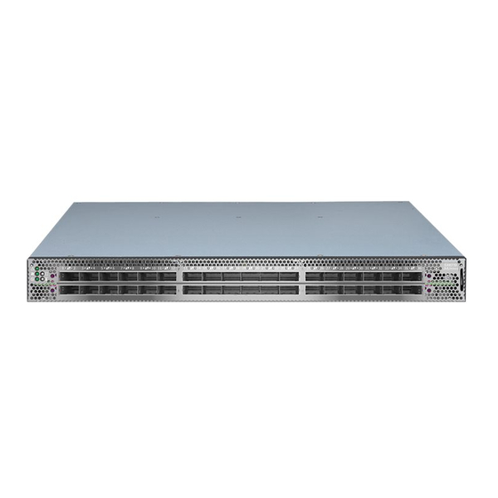
Mellanox's gateways enable data centers to operate at up to 56Gb/s network speeds while seamlessly connecting to 1, 10 and 40GbE networks with low latency (400ns). Existing LAN infrastructures and management practices can be preserved, easing deployment and provid- ing significant return-on-investment. Figure 1: SX67X0 Front Side View Mellanox Technologies... -
Page 11: Speed And Switching
Figure 2: SX6710/SX6720 Rear Side View [Grab your reader’s attention with a great quote from the document or use this space to emphasize a key point. To place this text box anywhere on the page, just drag it.] Figure 3: SX6730 Rear Side View... -
Page 12: Features
For more details, see “Air Flow” on page 8. Table 5 - Ordering Part Numbers (OPNs) System Description Model SX6710 MSX6710-FB2F2 SwitchX®-2 based FDR InfiniBand 1U Switch, 36 QSFP+ ports, 2 Power Supplies(AC), x86 dual core, short depth, rear to front airflow, Rail Kit, RoHS6 MSX6710-FS2F2 SwitchX®-2 based FDR InfiniBand 1U Switch, 36 QSFP+ ports, 2 Power Supplies(AC), x86 dual core, standard depth, rear... -
Page 13: Chapter 2 Installation
(Romanian),” on page 88. For Safety Warnings in Croatian, see Section E.10, “Sigurnosna upozorenja za instaliranje (Croa- tian),” on page 93. For Safety Warnings in Italian, see Section E.11, “Avvertenze di sicurezza per l’installazione (italiano),” on page 97. Mellanox Technologies... -
Page 14: Air Flow
Table 6 - Air Flow Color Legend Direction Description Designation Connector side inlet to power side outlet. Red latches are placed on the power inlet side. Power side inlet to connector side outlet. Blue latches are placed on the power inlet side. Mellanox Technologies... -
Page 15: Package Contents
Before installing your new system, unpack it and check against the parts list below that all the parts have been sent. Check the parts for visible damage that may have occurred during shipping. The SX6710 package content is as follows: • 1 – System •... - Page 16 For connection of the SX6730, a DC cable is required. Such a cable is not included in the basic package and should be ordered separately. If anything is damaged or missing, contact your sales representative at support@mella- nox.com. Mellanox Technologies...
-
Page 17: Mounting Options
Battery Backup Unit (BBU) Installation for SX6720 If the BBU is deformed, leaking, corroded or visually damaged, replace it immediately Do not use a BBU that was not provided by Mellanox Technologies • A BBU that has not been used for two years or longer past ts printed manufacturing date is unusable. -
Page 18: Figure 8: Unlocking The Latches And Extracting The Psu
Installation Figure 8: Unlocking the Latches and Extracting the PSU Figure 9: BBU Location Mellanox Technologies... -
Page 19: Figure 10: Bbu Insertion (Left) And Extraction (Right)
Figure 10: BBU Insertion (Left) and Extraction (Right) Mellanox Technologies... -
Page 20: Mounting Options
• 2x Rack mount brackets (B) • 2x Rack mount blades (C) • 8x M6 Standard cage nuts and 8x M6 Standard pan-head Phillips screws (D) • 4x Phillips100 DEG F.H TYPE-I ST.ST 6-32 X 1/4 screw with around patch (E). Mellanox Technologies... -
Page 21: Figure 11: Rack Rail Kit Parts
2) will determine the system’s adjustable side. The system’s part to which the brackets are attached, will be adjacent to the cabinet. • The FRU side is extractable. Mounting the rack brackets inverted to the FRU side (Option 2), will allow you to slide the FRUs, in and out. Mellanox Technologies... -
Page 22: Figure 12: Installation Options
Attach the left and right rack mount brackets (B) to the switch, by gently pushing the switch Step 5. chassis’ pins through the slider key holes, until locking occurs. Secure the system in the brack- ets by screwing the remaining 2 flat head Phillips screws (E) in the designated points. See Figure 14. Mellanox Technologies... -
Page 23: Figure 14: Attaching The Brackets To The Chassis
Slide the two blades into the left and right rails, and adjust them to fit your rack's depth. Use Step 8. four M6 screws (D) to fix the blades into the rack. Do not tighten the screws yet. Figure 15: Attaching the Brackets to the Rack Mellanox Technologies... -
Page 24: Figure 16: Sliding The Blades In The Rails
Loosen the screws attaching the blades to the rack, and pull the blades towards you, while your Step 3. partner is holding the system. Extract the loosened screws from Step 2 and dismount the system from the rack. Step 4. Remove the rails and brackets from the chassis by unscrewing 8 screws. Step 5. Mellanox Technologies... -
Page 25: 19" Systems Mounting- Telescopic Rail-Kit
• 2x Phillips100 DEG F.H TYPE-I ST.ST 6-32 X 1/4 screw with around patch (F). ¹ Other threads are available by special order: M5, 10-32, 12-24 ² G-type cage-nut is available by special order. NOTE: The rails must be separated prior to the installation procedure. See Figure 18. Mellanox Technologies... -
Page 26: Figure 17: Rack Rail Kit Parts
2. Extract rail A from rail C by pushing it outside from the rear part of the assembly. by pushing it outside from the rear part of the assembly. To allow complete separation of rail A from rail C, press the quick-release latch. Mellanox Technologies... -
Page 27: Figure 19: Mounting The Outer Rails Into The Rack
Secure the chassis in the inner rails screwing the 2 flat head Phillips screws (F) in the desig- Step 5. nated points. Figure 19: Mounting the Outer Rails into the Rack Mellanox Technologies... -
Page 28: Figure 20: Attaching The Inner Rails To The Chassis
Slide the switch into the rack by carefully pushing the inner rails into the outer rails installed on Step 6. the rack. When fully inserted, fix the switch by closing the remaining 2 screws in the middle and tighten- Step 7. ing the 8 screws inserted in Step 2 with a torque of Min 2Nm. Mellanox Technologies... -
Page 29: Figure 22: Sliding The Switch Into The Rack
Press on the locking spring (appears in red in Figure 24) on both sides simultaneously, and con- Step 4. tinue pulling the unit towards you until it is fully removed. Figure 23: Pulling the Unit Outwards Mellanox Technologies... -
Page 30: Cable Installation
For more information about port LEDs refer to Section 4.2.1.6, “Port LEDs,” on page 46. Do not force the cable into the cage with more than 40 newtons / 9.0 pounds force / 4kg force. Greater insertion force may cause damage to the cable or the cage. Mellanox Technologies... -
Page 31: Using A Breakout Cable
When using a port to split a data stream into four 10 Gb/s data streams and one of the other ports on the switch will be disabled and unmapped from the switch. When using this feature you should log into the MLNX-OS® CLI and configure the individual ports to be ‘split-2’ or ‘split-4’. Mellanox Technologies... -
Page 32: Figure 26: Breakout Or Fanout Cable
Can be split to 4 Can be split to 2 Port # Can be split to 4 Can be split to 2 Yes, disables port 1 Yes, disables port 19 Yes, disables port 5 Yes, disables port 23 Mellanox Technologies... - Page 33 Can be split to 4 Can be split to 2 Yes, disables port 7 Yes, disables port 19 Yes, disables port 11 Yes, disables port 23 Yes, disables port 13 Yes, disables port 31 Yes, disables port 17 Yes, disables port 35 Mellanox Technologies...
-
Page 34: Initial Power On
Step 4. with normal operation (initially flashing and then moving to a steady color) as shown in Figure 27 below. For more information, refer to “LEDs” on page 41. Figure 27: System Status LEDs 5 Minutes After Power On Mellanox Technologies... -
Page 35: Bring-Up Of Managed Systems
Since the system comes with a pre- configured DHCP, you may find the explanation in Section 2.8.1.1 sufficient. In case a manual configuration is required, please refer to the instructions in Section 2.8.1.2. Mellanox Technologies... -
Page 36: Table 10: Serial Terminal Program Configuration
Login as admin and use admin as password. On the first login, the MLNX-OS configuration Step 3. wizard will start. To configure network attributes and other initial parameters to the system, follow the configu- Step 4. ration wizard as shown in Table Mellanox Technologies... -
Page 37: Table 11: Configuration Wizard Session
To change an answer, enter the step number to return to or hit Note: <enter> to save changes and exit. To re-run the configuration wizard, run the command “configura- Choice: <Enter> tion jump-start” in Config mode. Configuration changes saved. Mellanox Technologies... -
Page 38: Table 12: Configuration Wizard Session - Static Ip Configuration
To change an answer, enter the step number to return to. Otherwise hit <enter> to save changes and exit. Choice: Configuration changes saved. To return to the wizard from the CLI, enter the “configuration jump-start” command from configure mode. Launching CLI... > Mellanox Technologies... -
Page 39: Remote Connection
Set up an Ethernet connection between the system and a local network machine using a stan- Step 1. dard RJ45 connector. Start a remote secured shell (SSH) using the command: “ssh -l <username> <IP_address>”, Step 2. # ssh -l <username> <ip address> Mellanox Technologies... -
Page 40: Fru Replacements
Grasping the handle with your hand, push the latch release with your thumb while pulling the Step 2. handle outward. As the power supply unit unseats, the power supply unit status LEDs will turn off. Remove the power supply unit. Step 3. Mellanox Technologies... -
Page 41: Fans
Make sure that the fans have the air flow that matches the model number. An air flow opposite to the system design will cause the system to operate at a higher (less than optimal) temperature. For power supply unit air flow direction, refer to Section 2.2 on page 8 Mellanox Technologies... -
Page 42: Figure 30: Fan Module Latches
The green Fan Status LED should light. If not, extract the fan unit and reinsert it. After system two unsuccessful attempts to install the fan unit, power off the before attempt- ing any system debug. Mellanox Technologies... -
Page 43: Chapter 3 Software Management
Fabric Inspector includes a complete set of InfiniBand tools for fabric wide diagnostics to check node-node and node-switch connectivity and to verify routes within the fabric. Advanced filtering allows creating filtering rules on a system wide basis, between nodes or port connections based on traffic patterns and user assigned system names (GUIDs). Mellanox Technologies... -
Page 44: Upgrading Software (On Managed Systems)
SwitchX®-2 based managed systems. MLNX-OS® includes a CLI, WebUI, SNMP, system management software and IB management software (OpenSM). The Ethernet ports for remote management connect to Ethernet systems. These sys- tems must be configured to 100Mb/1 Gb auto-negotiation. Mellanox Technologies... -
Page 45: Chapter 4 Interfaces
This interface is not found in externally managed systems. The port labeled “Console” is an RS232 serial port on the back side of the chassis that is used for initial configuration and debugging. Upon first installation of the system, you need to Mellanox Technologies... -
Page 46: Management
DO NOT use a sharp pointed object such as a needle or a push pin for pressing the Reset button. Use a flat object to push the reset button. To reset the system and the CPU of its management board, perform the following: Mellanox Technologies... -
Page 47: Leds
Bad Port LED lights up when a symbol error is detected on one of the ports. *Unit Identifier LED Lights up on command through the CLI Off or blue when identifying a port *This function is currently disabled. Mellanox Technologies... -
Page 48: Figure 31: System Status Leds - Front And Rear Sides
Mellanox representa- tive for assistance. 4.2.1.2 Fan Status LED Figure 32: Fan Status LED - Front and Rear Sides Both of these LEDs in the red circles show the fans’ status. Mellanox Technologies... -
Page 49: Figure 33: Power Status Led
In case the power supply is an FRU, a second power supply unit can be added to support hot-swap ability. Each power supply unit has a single 2 color LED on the right side of the unit, that indicates the status of the unit. Mellanox Technologies... -
Page 50: Figure 34: Rear Side Panel
Plug in the AC cord of the faulty PSU the second power supply still has AC input power. PS failure (including voltage out of range and Check voltage. If OK, call your Mella- power cord disconnected). nox representative for assistance Mellanox Technologies... -
Page 51: Table 19: Bad Port Led Assignments
Error, one or more ports have received symbol Check symbol error counters on the sys- errors. tem UI to identify the ports. Possible causes are: Replace the cable on these ports. • Bad cable • Bad connection • Bad connector Mellanox Technologies... -
Page 52: Figure 35: Port Leds
When a logical connection is made the LED will change to green. When data is being transferred the light will blink green. Mellanox Technologies... -
Page 53: Inventory Pull-Out Tab
Inventory Pull-out Tab The system’s inventory parameters (such as serial number, part number, GUID and MAC address) can be extracted from the Inventory pull-out tab on the lower right side of the front panel. Figure 36: Pull-out Tab Mellanox Technologies... -
Page 54: Chapter 5 Troubleshooting
This state is indicative of a problem with the PSU. • Check/replace the power cable. • Replace the PSU if needed. The activity LED does not Make sure that there is an SM running in the fabric. light up (InfiniBand): Mellanox Technologies... - Page 55 Press enter to boot the selected image or 'p' to enter a password to unlock the next set of features. Highlighted entry is 0: " • Select previous image to boot by pressing an arrow key and choosing the appropriate image. Mellanox Technologies...
-
Page 56: Chapter 6 Specifications
Short - 1.716” (H) H x 16.85” (W) x16.8” (D), 43.6mm (H) x 428mm (W) x 428.9 mm (D) Standard - 1.716” (H) H x 16.85” (W) x24.75” (D), 43.6mm (H) x 428mm (W) x 722.3 mm (D) Mounting: 19” Rack mount Weight: SX6710 Long: 2 PSUs: 10.86kg Short: 2 PSUs: 8.5kg SX6720 (Long) 2 PSUs: 11.75kg... - Page 57 When the SwitchX®/SwitchX-2 device crosses this temperature, the firmware will automatically shut down the device. 3.Emergency – 130°C In case the firmware fails to shut down the SwitchX®/SwitchX-2 device upon crossing the Criti- cal threshold, the SwitchX® device will auto-shutdown upon crossing the Emergency (130°C) threshold. Mellanox Technologies...
-
Page 58: Appendix A Accessory And Replacement Parts
Fan module w/rear to front airflow fan with Orange cap for SX67X0 switch systems MTEF-FANR-A Fan module w/front to rear airflow fan for SX67X0/SX1710 switch systems MTEF-BBU-A Battery Backup Unit for MSX67X0 switch systems **[Lithium ion batteries in compliance with Section II of PI 965]** Mellanox Technologies... -
Page 59: Appendix C Interface Specifications
Vcc Tx +3.3 V Power supply transmitter Vcc 1 +3.3 V Power Supply LPMode Low Power Mode Ground Tx3p Transmitter Non-Inverted Data Input Tx3n Transmitter Inverted Data Input Ground Tx1p Transmitter Non-Inverted Data Input Tx1n Transmitter Inverted Data Input Mellanox Technologies... - Page 60 Figure 37: QSFP Connector Male and Female Views 18.35 View into Rear of Connector 8.50 18.35 View into Front of Cage 8.50 Mellanox Technologies...
-
Page 61: Rj-45 Console And I²C Interface
Not connected RJ45 to DB9 Harness Pinout In order to connect a host PC to the Console RJ45 port of the system, a RS232 harness cable (DB9 to RJ45) is supplied. Figure 38: RJ45 to DB9 Harness Pinout Mellanox Technologies... -
Page 62: Appendix D Disassembly And Disposal
(EEE) should be collected separately and not disposed of with regular household waste. Dispose of this product and all of its parts in a responsible and environmentally friendly way. Follow the instructions found at http://www.mellanox.com/page/dismantling_procedures for proper disassembly and disposal of the switch, according to the WEEE directive. Mellanox Technologies... -
Page 63: Appendix E Safety Warnings (Multiple Languages)
5. Over-temperature This equipment should not be operated in an area with an ambient temperature exceed- ing the maximum recommended: 45°C (113°F). Moreover, to guarantee proper , allow at least 8cm (3 inches) of clearance around the ventilation openings. Mellanox Technologies... - Page 64 When this product is mounted or serviced in a rack, special precautions must be taken to ensure that the system remains stable. In general you should fill the rack with equip- ment starting from the bottom to the top. Mellanox Technologies...
- Page 65 For European connection, select a power supply cord that is internationally harmonized and marked “<HAR>”, 3 - conductor, minimum 1.0 mm wire, rated at 300 V, with a PVC insulated jacket. The cord must have a molded plug rated at 250 V, 10 A. Mellanox Technologies...
- Page 66 Caution: Slide/rail mounted equipment is not to be used as a shelf or a work space. The rails are not intended for sliding the unit away from the rack. It is for permanent instal- lation at final resting place only, not used for service and maintenance Mellanox Technologies...
- Page 67 If the BBU is deformed, leaking, corroded or visually damaged, replace it immedi- ately. Do not use a BBU that was not provided by Mellanox Technologies. • A BBU that has not been used for two years or longer past its printed manu- facturing date is unusable.
- Page 68 תקן ישראלי חבלת גוף כתוצאה מנשיאת משקל יתר ציוד כבד !סכנת התחשמלות 6. התחממות יתר ערימת המערכת חיבור ספק כוח נוסף -סכנת חשמל Mellanox Technologies...
- Page 69 מספר שקעים חשמליים 10. בעת סופות ברקים - סכנת חשמל 11. חיבור או ניתוק של כבלי אינפיניבאנד מנחושת 12. הרכבה על גבי מדף בארון 13. התקנת המוצר 14. השלכת פסולת 15. תקנות חשמל מקומיות ולאומיות Mellanox Technologies...
- Page 70 16. כבל אספקת חשמל 17. תקנות התקנה חיבור בין מערכות 19. הגנה מפני מתח גבוה 20. אין להשתמש במערכת כמדף או שטח עבודה 21. WEEE תקנת Mellanox Technologies...
-
Page 71: 安裝安全性警告 (Chinese)
22. מגבלות חשמליות בנורבגיה 23. BBU 安裝安全性警告 (Chinese) 1. 安裝指示 本設備附有備援電源供應器或在適當位置配有空白蓋板。 2. 因重量導致的人身受傷 為了安全起見,請安排足夠的人員以合力抬起本產品。 <40 lbs 70 - 121 lbs >121 lbs 40 - 70 lbs <18 kgs 32 - 55 kgs >55 kgs 18 - 32 kgs Mellanox Technologies... - Page 72 4. 有觸電的危險 有觸電的危險! 拆除風扇模組後,即可接觸到模組空腔內的電源針腳。 請勿將工具或機身零件插入到風扇模組空腔內。 5. 溫度過高 本設備不應在超過所建議的最高環境溫度的區域中運作:45°C (113°F)。此外, 為了保證氣流的流通正常,請在通風口旁保留至少 8 公分 (3 英吋 ) 的間距。 6. 堆疊機箱 機箱不應堆疊在任何其他設備上。如果機箱掉落,可能造成人員受傷與設備損 壞。 7. 複式電源連接時的電擊危險 本設備附有備援電源供應器或在適當位置配有空白蓋板。如果是電源供應器空 白蓋板,在空白蓋板已取下或未牢牢固訂的情況下,請勿操作本產品。 8. 雙極 / 中性保險絲 本系統具有雙極 / 中性保險絲。請拔掉所有電源線後,再打開本產品的蓋板或 碰觸任何內部零件。 9. 多電源輸入座 電擊與能源危害的危險。 所有 PSU 均各自獨立。 將所有電源供應器斷電,確保交換器平台內部在電源關閉狀態。 Mellanox Technologies...
- Page 73 10. 閃電時的電擊危險 在閃電期間,不要使用本設備或連接或拔下纜線。 11. InfiniBand 銅纜連接 / 拔下 InfiniBand 銅纜很重且沒有彈性,因此必須小心裝在連接器上或自連接器上拔 下。如需相關的特殊警告 / 指示,請洽詢纜線製造商。 12. 機架安裝與維修 此產品已安裝在機架中或在機架中維修時,必須採取特定預防措施以確保系統 維持穩定。一般您應該將設備從底部到頂端放滿機架。 13. 設備安裝 本設備僅限由經過訓練與 / 或合格的人員安裝、更換或維修。 14. 設備棄置 棄置本設備應遵照所有國內法規。 15. 當地與國家電氣法規 請遵照當地與國家電氣法規安裝本設備。 16. 安裝法規 請務必遵循最新版的國家電氣法規,安裝本設備。在北美地區,請務必遵循美 國國家電工法規和加拿大電工法規中的適用規定,安裝本設備。 Mellanox Technologies...
- Page 74 維修人員應檢查插座 ( 供電給設備的插座 ) 是否提供連接大樓保護地線的方式。 如果沒有,維修人員應安排從獨立保護地線端子,將保護接地導體安裝至大樓 的保護地線。設備應安裝於有等電位聯結的區域 ( 例如,電信中心或專用電腦 室 )。 21. 安裝法規 請務必遵循最新版的國家電氣法規,安裝本設備。在北美地區,請務必遵循美 國國家電工法規和加拿大電工法規中的適用規定,安裝本設備。 22. 互連設備 連接至 RS232 設備和乙太網路介面的纜線必須是 UL 認證類型 DP-1 或 DP-2。 ( 請注意位於非 LPS 電路時 ) 過電流保護:準備好使用的列名分支電路過電流保護裝置最大額定值 20 A 必須 整合在配線中。 23. 切換開關不可用作機架或工作空間 小心:滑軌 / 導軌安裝設備不可用作機架或工作空間。導軌不適用於將設備滑 出機架使用。僅限永久安裝在最後安置區域時使用,不可用於維修和保養。 Mellanox Technologies...
- Page 75 24. WEEE 指令 根據 WEEE 指令 2002/96/EC,所有廢棄的電氣與電子設備 (EEE),應分開集 中,而且不應與一般家庭廢棄物一起棄置。 請以負責和環保的方式棄置本產品及其所有零件。 25. 挪威國家電源限制 本設備僅限連接至挪威的 TN 電源系統和 IT 電源系統。 26. BBU 如果 BBU (备用电池)变形、漏液、被腐蚀或有可见损坏,请立即更换。 请勿使用非 Mellanox Technologies 供应的 BBU(备用电池) 根据印刷的制造日期计算,寿命超过五年的 BBU (备用电池)已达到 “ 寿命终 止 ” 状态,可能无法为平台提供足够的电力。 当电池需要更换时,从其寿命终止前三个月开始将每个月显示软件通知。 Mellanox Technologies...
- Page 76 27. China CCC Warning Statement Mellanox Technologies...
-
Page 77: Avertissements De Sécurité Pour L'installation (French)
8 cm (3") autour des orifices de ventilation. 6. Châssis empilé sur d'autres équipements Le châssis ne doit pas être empilé sur d'autres équipements. S'il tombe, il peut endom- mager l'équipement ou entraîner des blessures. Mellanox Technologies... - Page 78 En règle générale, le rack doit être rempli en commençant par le bas. 13. Installation de l'équipement Cet équipement ne doit être installé, remplacé et maintenu que par un personnel formé et qualifié. Mellanox Technologies...
- Page 79 300 V, avec une gaine isolante en PVC. Le cordon doit avoir une prise moulée 250 V 10 A. 19. Courant de fuite élevé Avertissement : courant de fuite élevé, une connexion à la terre est indispensable avant de brancher l'alimentation. Mellanox Technologies...
- Page 80 Selon la Directive 2002/96/CE (DEEE), tous les déchets d'équipements électriques et électroniques (EEE) doivent être collectés séparément et ne pas être mis au rebut avec les déchets ménagers habituels. Ce produit et toutes ses pièces doivent être mis au rebut d'une manière responsable, respectant l'environnement. Mellanox Technologies...
-
Page 81: Installation Sicherheitshinweise(German)
2. Verletzungsgefahr wegen des Gewichts Um das Produkt sicher anzuheben, genügend Personen einsetzen. <40 lbs 70 - 121 lbs >121 lbs 40 - 70 lbs <18 kgs 32 - 55 kgs >55 kgs 18 - 32 kgs Mellanox Technologies... - Page 82 Alle Stromversorgungseinheiten sind unabhängig. Trennen Sie alle Stomversorgungen, um einen abgeschalteten Zustand im Inneren der Switch-Plattform sicherzustellen. 8. Bei Gewitter - Elektrische Gefahr Arbeiten Sie während eines Gewitters und Blitzschlag nicht am Gerät, schließen Sie keine Kabel an oder ab. Mellanox Technologies...
- Page 83 Warnung: Nur durch von UL anerkannten Akkus ersetzen, die für maximalen anor- malen Ladestrom von nicht weniger als 4mA zertifiziert sind. Es besteht Explosiionsgefahr, wenn der Akku durch einen Akku eines falschen Typs ersetzt wird. Akkus gemäß den Anweisungen entsorgen. Mellanox Technologies...
- Page 84 Achtung: Auf Schieber/Schienen montiertes Gerät ist nicht als Regal oder Arbeitsbere- ich zu nutzen. Die Schienen sind nicht dafür bestimmt, die Einheit aus dem Gestell weg zu ziehen. Sie sind nur für die permanente Installation an einem endgültigen Stan- dort gedacht, nicht für Instandhaltung und Wartung. Mellanox Technologies...
-
Page 85: Advertencias De Seguridad De Instalación (Spanish)
2. Lesión corporal a causa de peso .Recurra a suficientes personas para levantar este producto sin <40 lbs 70 - 121 lbs >121 lbs 40 - 70 lbs <18 kgs 32 - 55 kgs >55 kgs 18 - 32 kgs Mellanox Technologies... - Page 86 9. Tomas de alimentación múltiples Riesgo de descarga eléctrica y peligro de corriente. Todas las fuentes de alimentación son independientes. Desconecte todas las fuentes de alimentación, para asegurar que no haya corriente alguna dentro de la plataforma de conmutación. Mellanox Technologies...
- Page 87 Este dispositivo se debe instalar conforme a la versión más reciente de los códigos eléctricos nacionales del país en cuestión. En América del Norte, el equipo se debe instalar de acuerdo con las disposiciones vigentes del Código Eléctrico Nacional de los EE.UU. y del Código Eléctrico de Canadá. Mellanox Technologies...
- Page 88 En América del Norte, el equipo se debe instalar de acuerdo con las disposiciones vigentes del Código Eléctrico Nacional de los EE.UU. y del Código Eléctrico de Canadá. 22. Interconexión de unidades Mellanox Technologies...
- Page 89 No utilice una BBU (Unidad de Batería de Respaldo) que no haya sido provista por Mellanox Technologies. * Una BBU (Unidad de Batería de Respaldo) que no ha sido utilizada durante dos años o más luego de su fecha de fabricación impresa no es utilizable.
-
Page 90: Предупреждения По Технике Безопасности При Установке (Russian)
Более того, для надлежащей вентиляции следует обеспечить зазор вокруг вентиляционных отверстий не менее 8 см (3 дюйма). 6. Установка шасси поверх другого оборудования Не устанавливать шасси поверх другого оборудования. Падение шасси может привести к травмам и повреждению оборудования. Mellanox Technologies... - Page 91 12. Установка или обслуживание в стойке При установке или обслуживании этого изделия в стойке следует обеспечить устойчивость системы. Как правило, стойка заполняется оборудованием снизу вверх. 13. Установка оборудования Устанавливать, заменять и/или обслуживать это оборудование должен только подготовленный и квалифицированный персонал. Mellanox Technologies...
- Page 92 сечением жилы не менее 1,0 мм², рассчитанного на номинальное напряжение 300 В, с ПВХ оболочкой. Шнур должен иметь литую вилку, рассчитанную на 250 В, 10 А. 19. Высокий ток утечки Осторожно! Высокий ток утечки. Заземлить перед подключением к электропитанию. Mellanox Technologies...
- Page 93 24. Директива WEEE В соответствии с Директивой 2002/96/EC (WEEE) отходы электрического и электронного оборудования должны собираться и утилизироваться отдельно от обычных бытовых отходов. Следует утилизировать это изделие и все его части ответственным и экологически безопасным способом. 25. BBU Mellanox Technologies...
-
Page 94: Avertismente Privind Siguranţa La Instalare (Romanian)
Если BBU (резервный аккумулятор) деформируется, течет, на нем видны повреждения или признаки коррозии, немедленно замените его. Не используйте BBU (резервный аккумулятор), не поставленный компанией Mellanox Technologies * BBU (резервный аккумулятор), изготовленный более семи лет назад в соответствии с указанной датой производства, достиг завершения срока службы... - Page 95 Deconectaţi toate sursele de alimentare cu energie pentru a asigura decuplarea în inter- iorul platformei de comutare. 10. În timpul descărcărilor electrice - pericol electric În timpul perioadelor cu descărcări electrice luminoase, nu lucraţi cu echipamentul sau nu conectaţi sau deconectaţi cablurile. Mellanox Technologies...
- Page 96 Avertisment: Înlocuiţi numai cu o baterie recunoscută UL, certificată pentru curent de încărcare anormal maxim de minimum 4 mA Există risc de explozie în cazul în care bateria este înlocuită cu o baterie necorespun- zătoare. Eliminaţi bateriile folosite în conformitate cu instrucţiunile. Mellanox Technologies...
- Page 97 DP-1 sau DP-2 certificate UL. (Notă- când se regăsesc într-un circuit non-LPS) Protecţie la supracurent: Un dispozitiv de protecţie la supracurent, înregistrat în cir- cuitul de ramificare, uşor accesibil şi cu o putere nominală egală cu 20 A trebuie să fie integrat în cablajul clădirii. Mellanox Technologies...
- Page 98 * O Unitate de baterie de rezervă care este mai veche de cinci ani, conform datei de fabricaţie inscripţionate, a atins „sfârşitului duratei de viaţă“ şi nu poate furniza sufi- cientă energie pentru manevrarea platformei Mellanox Technologies...
-
Page 99: Sigurnosna Upozorenja Za Instaliranje (Croatian)
45°C (113°F). Osim toga, kako bi se osigu- rao odgovarajući protok zraka, omogućite najmanje 8 cm (3 inča) razmaka oko otvora ventilatora. 6. Slaganje kućišta Kućište se ne bi trebalo slagati na drugu opremu. Ako kućište padne, može izazvati tje- lesne ozljede i oštećenje opreme. Mellanox Technologies... - Page 100 Općenito, trebali biste ispunja- vati ormarić s opremom počevši od dna prema vrhu. 13. Instaliranje opreme Ovu bi opremu trebalo instalirati, zamjenjivati i/ili servisirati samo obučeno i kvalifici- rano osoblje. Mellanox Technologies...
- Page 101 žice, nazivnog napona od 300 V, s PVC izolacijom. Kabel mora imati lijevani utikač nazivnog napona od 250 V, nazivne struje od 10 A. 19. Veliko curenje struje Upozorenje: Veliko curenje struje; Prije spajanja napajanja nužno je spojiti uzeml- jenje. Mellanox Technologies...
- Page 102 Sukladno WEEE direktivi 2002/96/EZ, sav električni i elektronički otpad (EEE) trebao bi se prikupljati zasebno i ne bi se trebao odlagati kao običan kućanski otpad. Odlaganje ovog proizvoda i svih njegovih dijelova vršite na odgovoran i ekološki način. Mellanox Technologies...
-
Page 103: Avvertenze Di Sicurezza Per L'installazione (Italiano)
2. Lesioni a causa del peso Usare un numero di persone sufficiente per sollevare in sicurezza questo prodotto. <40 lbs 70 - 121 lbs >121 lbs 40 - 70 lbs <18 kgs 32 - 55 kgs >55 kgs 18 - 32 kgs Mellanox Technologies... - Page 104 9. Prese di alimentazione multiple Rischio e pericolo di scosse elettriche. Gli alimentatori sono tutti indipendenti. Scollegare tutti gli alimentatori per assicurarsi che il commutatore non sia sotto tensione Mellanox Technologies...
- Page 105 Questo dispositivo va installato in conformità con l’ultima versione dei codici elettrici nazionali del Paese. Per il Nord America, l’apparecchiatura va installata in conformità con i requisiti applicabili del “codice elettrico nazionale USA” e del “codice elettrico canadese”. Mellanox Technologies...
- Page 106 Questo dispositivo va installato in conformità con l’ultima versione dei codici elettrici nazionali del Paese. Per il Nord America, l’apparecchiatura va installata in conformità con i requisiti applicabili del “codice elettrico nazionale USA” e del “codice elettrico canadese”. Mellanox Technologies...
- Page 107 Secondo la direttiva RAEE 2002/96/EC, tutti i rifiuti da apparecchiature elettriche ed elettroniche (RAEE) vanno raccolti separatamente e non smaltiti nei normali rifiuti domestici. Smaltire questo prodotto e tutte le sue parti in modo responsabile e rispettoso dell’ambiente Mellanox Technologies...
-
Page 108: Montaj Güvenlik Uyarıları (Türkçe)
2. Ağırlık Nedeniyle Fiziksel Yaralanma Bu ürünü güvenli bir şekilde kaldırabilmek için yeterli sayıda insandan yardım alın.. <40 lbs 70 - 121 lbs >121 lbs 40 - 70 lbs <18 kgs 32 - 55 kgs >55 kgs 18 - 32 kgs Mellanox Technologies... - Page 109 önce bütün güç kablolarını çıkartın. 9. Çoklu Güç Girişleri Elektrik çarpması riski ve enerji tehlikesi. Bütün PSU'lar (Güç Kaynağı Üniteleri) ayrıdır. Anahtar platformundaki gücü kapatmak için tüm güç kaynaklarının bağlantılarını kesin. Mellanox Technologies...
- Page 110 Bu ekipmanın montajında yerel ve ulusal elektrik kodlarına uyulması gerekir. 16. Montaj Kodları Bu cihazın, ülke ulusal elektrik kodlarının son sürümüne göre monte edilmesi gerekir. Kuzey Amerika için, ekipmanın ABD Ulusal Elektrik Kodu ve Kanada Elektrik Kodu'nun uygulama koşullarına göre monte edilmesi gerekir. Mellanox Technologies...
- Page 111 özel görevli bilgisayar odası gibi). 21. Montaj Kodlarıi Bu cihazın, ülke ulusal elektrik kodlarının son sürümüne göre monte edilmesi gerekir. Kuzey Amerika için, ekipmanın ABD Ulusal Elektrik Kodu ve Kanada Elektrik Kodu'nun uygulama koşullarına göre monte edilmesi gerekir. Mellanox Technologies...
- Page 112 Yedek Batarya Ünitesi (Backup Battery Unit - BBU) deforme olmuşsa, akıyorsa, korozyona uğramışsa ya da hasarlı bir görünüme sahipse derhal değiştirin. Mellanox Technologies tarafından temin edilmeyen Yedek Batarya Ünitelerini (BBU) kullanmayın. * İki yıl süre ile kullanılmamış veya üzerindeki üretim tarihinde belirtilen süreyi aşmış...
Need help?
Do you have a question about the SX6710 and is the answer not in the manual?
Questions and answers