
Related Manuals for Mellanox Technologies SB7700


Summary of Contents for Mellanox Technologies SB7700
- Page 1 Mellanox 1U EDR 100Gb/s InfiniBand Switch Systems Hardware User Manual Models: SB7700/SB7790 Rev 1.2 www.mellanox.com...
- Page 2 KIND AND SOLELY FOR THE PURPOSE OF AIDING THE CUSTOMER IN TESTING APPLICATIONS THAT USE THE PRODUCTS IN DESIGNATED SOLUTIONS. THE CUSTOMER'S MANUFACTURING TEST ENVIRONMENT HAS NOT MET THE STANDARDS SET BY MELLANOX TECHNOLOGIES TO FULLY QUALIFY THE PRODUCT(S) AND/OR THE SYSTEM USING IT. THEREFORE, MELLANOX TECHNOLOGIES CANNOT AND DOES NOT GUARANTEE OR WARRANT THAT THE PRODUCTS WILL OPERATE WITH THE HIGHEST QUALITY.
-
Page 3: Table Of Contents
4.2.1 LED Notifications ..........40 Mellanox Technologies... - Page 4 E.11 Avvertenze di sicurezza per l’installazione (italiano) ....86 E.12 Montaj Güvenlik Uyarıları (Türkçe) ....... 90 Mellanox Technologies...
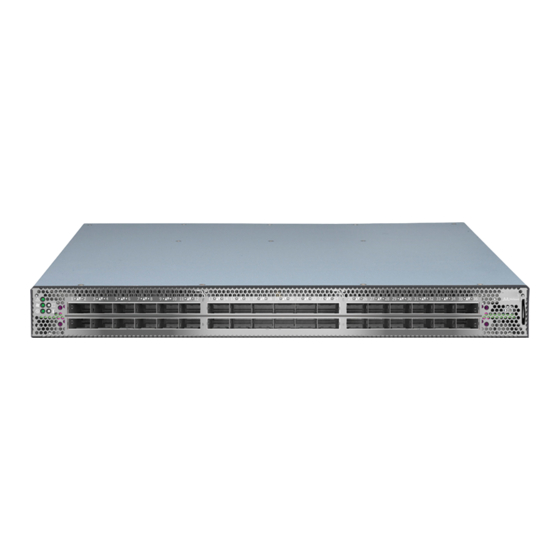
- Page 5 SB7700 and SB7790 Front Side View ........
- Page 6 RJ-45 CONSOLE and I²C Pinout ......... . . 54 Mellanox Technologies...
-
Page 7: Revision History
Table 1 - Revision History Table Date Revision Description July 2015 Changed document’s title June 2015 Added: • Hebrew safety warnings Updated: • Figure 1,“SB7700 and SB7790 Front Side View” • Table 21, “SB77X0 Specifications” April 2015 Initial release Mellanox Technologies... -
Page 8: About This Manual
This icon makes recommendations to the user. This icon indicates information that is helpful to the user. This icon indicates a situation that can potentially cause damage to hardware or software. This icon indicates a situation that can potentially cause personal injury. Mellanox Technologies... -
Page 9: Chapter 1 Introduction To Mellanox Sb77X0 Systems
These features ensure the maximum effective fabric bandwidth by eliminating congestion. SB7700, dual-core x86 CPU, comes with an onboard subnet manager, enabling simple, out-of- the-box fabric bring-up for up to 2048 nodes. -
Page 10: Speed And Switching
Rev 1.2 Introduction to Mellanox SB77X0 Systems Figure 1: SB7700 and SB7790 Front Side View Figure 2: SB7700 Rear Side View Figure 3: SB7790 Rear Side View Speed and Switching Table 3 describes maximum throughput and interface speed per system model. -
Page 11: Features
For more details, see “Air Flow” on page 13. Table 5 - Ordering Part Numbers (OPNs) System Description Model SB7700 MSB7700-ES2F Switch-IB™ based EDR InfiniBand 1U Switch, 36 QSFP28 ports, 2 Power Supplies (AC), x86 dual core, standard depth, P2C airflow, Rail Kit, RoHS6 MSB7700-ES2R Switch-IB™... -
Page 12: Chapter 2 Installation
безопасности при установке (Russian),” on page 76. • For Safety Warnings in Romanian, see Section E.9, “Avertismente privind siguranţa la instalare (Romanian),” on page 79. • For Safety Warnings in Croatian, see Section E.10, “Sigurnosna upozorenja za instali- ranje (Croatian),” on page 83. Mellanox Technologies... -
Page 13: Air Flow
Table 6 - Air Flow Color Legend Direction Description Designation Connector side inlet to power side outlet. Red latches are placed on the power inlet side. Power side inlet to connector side outlet. Blue latches are placed on the power inlet side. Mellanox Technologies... -
Page 14: Package Contents
• 1 x System • 1 x Rail kit • 2 x Power cables – Type C13-C14 • 1 x Harness: HAR000028 – Harness RS232 2M cable – DB9 to RJ-451 (in SB7700 models only) • 2 x Cable retainers •... -
Page 15: Mounting Options
• 2x Rack mount brackets (B) • 2x Rack mount blades (C) • 8x M6 Standard cage nuts and 8x M6 Standard pan-head Phillips screws (D) • 4x Phillips100 DEG F.H TYPE-I ST.ST 6-32 X 1/4 screw with around patch (E). Mellanox Technologies... -
Page 16: Figure 6: Rack Rail Kit Parts
2) will determine the system’s adjustable side. The system’s part to which the brackets are attached, will be adjacent to the cabinet. • The FRU side is extractable. Mounting the rack brackets inverted to the FRU side (Option 2), will allow you to slide the FRUs, in and out. Mellanox Technologies... -
Page 17: Figure 7: Installation Options
Attach the left and right rack mount brackets (B) to the switch, by gently pushing the switch Step 2. chassis’ pins through the slider key holes, until locking occurs. Secure the system in the brack- ets by screwing the remaining 2 flat head Phillips screws (E) in the designated points. See Figure 9. Mellanox Technologies... -
Page 18: Figure 9: Attaching The Brackets To The Chassis
Slide the two blades into the left and right rails, and adjust them to fit your rack's depth. Use Step 5. four M6 screws (D) to fix the blades into the rack. Do not tighten the screws yet. Figure 10: Attaching the Brackets to the Rack Mellanox Technologies... -
Page 19: Figure 11: Sliding The Blades In The Rails
Loosen the screws attaching the blades to the rack, and pull the blades towards you, while your Step 3. partner is holding the system. Extract the loosened screws from Step 2 and dismount the system from the rack. Step 4. Remove the rails and brackets from the chassis by unscrewing 8 screws. Step 5. Mellanox Technologies... -
Page 20: 19" Systems Mounting- Telescopic Rail-Kit
• 2x Phillips100 DEG F.H TYPE-I ST.ST 6-32 X 1/4 screw with around patch (F). ¹ Other threads are available by special order: M5, 10-32, 12-24 ² G-type cage-nut is available by special order. NOTE: The rails must be separated prior to the installation procedure. See Figure 13. Mellanox Technologies... -
Page 21: Figure 12: Rack Rail Kit Parts
Extract rail A from rail C by pushing it outside from the rear part of the assembly. by pushing it Step 2. outside from the rear part of the assembly. To allow complete separation of rail A from rail C, press the quick-release latch. Mellanox Technologies... -
Page 22: Figure 14: Mounting The Outer Rails Into The Rack
Secure the chassis in the inner rails screwing the 2 flat head Phillips screws (F) in the desig- Step 5. nated points. Figure 14: Mounting the Outer Rails into the Rack Mellanox Technologies... -
Page 23: Figure 15: Attaching The Inner Rails To The Chassis
Slide the switch into the rack by carefully pushing the inner rails into the outer rails installed on Step 6. the rack. When fully inserted, fix the switch by closing the remaining 2 screws in the middle and tighten- Step 7. ing the 8 screws inserted in Step 2 with a torque of Min 2Nm. Mellanox Technologies... -
Page 24: Figure 17: Sliding The Switch Into The Rack
Press on the locking spring (appears in red in Figure 19) on both sides simultaneously, and con- Step 4. tinue pulling the unit towards you until it is fully removed. Figure 18: Pulling the Unit Outwards Mellanox Technologies... -
Page 25: Figure 19: Locking Mechanism
Rev 1.2 Figure 19: Locking Mechanism Mellanox Technologies... -
Page 26: Cable Installation
For more information about port LEDs refer to Section 4.2.1.6, “Port LEDs,” on page 45. Do not force the cable into the cage with more than 40 newtons / 9.0 pounds force / 4kg force. Greater insertion force may cause damage to the cable or the cage. Figure 20: Cable Orientation Mellanox Technologies... -
Page 27: Initial Power On
Step 4. with normal operation (initially flashing and then moving to a steady color) as shown in Figure 21 below. For more information, refer to “LEDs” on page 40. Figure 21: System Status LEDs 5 Minutes After Power On Mellanox Technologies... -
Page 28: Bring-Up Of Managed Systems
Mellanox Switch Mellanox configuration wizard Do you want to use the wizard for initial configuration? yes Step 1: Hostname? [my-switch] Step 2: Use DHCP on mgmt0 interface? [yes] no <localhost># In such case the serial connection should be used. Mellanox Technologies... -
Page 29: Table 9: Serial Terminal Program Configuration
Step 3: Enable IPv6? [yes] The management interface will be able to use IPv6 addresses. Step 4: Enable IPv6 auto-config This turns on auto-configuration of the IPv6 addresses. This is (SLAAC) on mgmt0 interface? unsuitable for DHCPv6. [no] Mellanox Technologies... -
Page 30: Table 11: Configuration Wizard Session - Static Ip Configuration
To change an answer, enter the step number to return to. Otherwise hit <enter> to save changes and exit. Choice: Configuration changes saved. To return to the wizard from the CLI, enter the “configuration jump-start” command from configure mode. Launching CLI... > Mellanox Technologies... -
Page 31: Remote Connection
Set up an Ethernet connection between the system and a local network machine using a stan- Step 1. dard RJ45 connector. Start a remote secured shell (SSH) using the command: “ssh -l <username> <IP_address>”, Step 2. # ssh -l <username> <ip address> Mellanox Technologies... -
Page 32: Fru Replacements
Grasping the handle with your hand, push the latch release with your thumb while pulling the Step 2. handle outward. As the power supply unit unseats, the power supply unit status LEDs will turn off. Remove the power supply unit. Step 3. Mellanox Technologies... -
Page 33: Fans
Make sure that the fans have the air flow that matches the model number. An air flow opposite to the system design will cause the system to operate at a higher (less than optimal) temperature. For power supply unit air flow direction, refer to Section 2.2 on page 13 Mellanox Technologies... -
Page 34: Figure 24: Fan Module Latches
The green Fan Status LED should light. If not, extract the fan unit and reinsert it. After system two unsuccessful attempts to install the fan unit, power off the before attempt- ing any system debug. Mellanox Technologies... -
Page 35: Chapter 3 Software Management
Fabric Inspector includes a complete set of InfiniBand tools for fabric wide diagnostics to check node-node and node-switch connectivity and to verify routes within the fabric. Advanced filtering allows creating filtering rules on a system wide basis, between nodes or port connections based on traffic patterns and user assigned system names (GUIDs). Mellanox Technologies... -
Page 36: Upgrading Software (On Managed Systems)
In order to obtain the firmware version of the externally managed system: Obtain the LID of the target system. The following instructions use one of the utilities provided Step 1. by the installed MFT package. (Other methods are described in the MFT User Manual.) by per- forming the following: Mellanox Technologies... - Page 37 Step c. Mark the displayed LID on that row (a decimal number). Run the following command from a host Step 2. flint -d lid-[number] -i <image> b For further information, please refer to MFT User Manual: http://www.mellanox.com/pdf/MFT/ MFT_user_manual.pdf Mellanox Technologies...
-
Page 38: Chapter 4 Interfaces
RS232 serial port on the back side of the chassis that is used for initial configuration and debugging. Upon first installation of the system, you need to connect a PC to this interface and configure network parameters for remote connections. Refer to Section 2.7.1 to view the full procedure. Mellanox Technologies... -
Page 39: Management
The reset button is located on the rear side of the system next to the fan status LEDs. This reset button requires a tool to be pressed. DO NOT use a sharp pointed object such as a needle or a push pin for pressing the Reset button. Use a flat object to push the reset button. Mellanox Technologies... -
Page 40: Leds
Bad Port LED Lights up when a symbol error is detected on one of the ports. *Unit Identifier LED Beacon LED, lights up on command through the Off or blue when identifying port *This function is currently disabled. Mellanox Technologies... -
Page 41: Figure 25: System Status Leds - Front And Rear Sides
Solid Red An error has occurred. For example, cor- If the System Status LED shows Red five rupted firmware, system is overheated etc. minutes after starting the system, unplug the system and call your Mellanox representa- tive for assistance. Mellanox Technologies... -
Page 42: Figure 26: Fan Status Led - Front And Rear Sides
The fan unit should be replaced. operating properly. System boot Risk of Electric Shock! With the fan module removed, power pins are accessible within the module cavity. DO NOT insert tools or body parts into the fan module cavity. Mellanox Technologies... -
Page 43: Figure 27: Power Status Led
One or both of the power supplies are not Make sure the AC cable is plugged in operational or not powered up/ the AC power and active. If the problem resumes, the cable is disconnected FRUs might be faulty, and should then be replaced. Mellanox Technologies... -
Page 44: Table 17: Power Supply Unit Status Rear Led Assignments
Error, one or more ports have received symbol Check symbol error counters on the sys- errors. tem UI to identify the ports. Possible causes are: Replace the cable on these ports. • Bad cable • Bad connection • Bad connector Mellanox Technologies... -
Page 45: Figure 29: Port Leds
When a logical connection is made the LED will change to green. When data is being transferred the light will blink green. Mellanox Technologies... -
Page 46: Inventory Pull-Out Tab
Interfaces Inventory Pull-out Tab The system’s inventory parameters (such as serial number, part number and GUID address) can be extracted from the inventory pull-out tab on the lower right side of the front panel. Figure 30: Pull-out Tab Mellanox Technologies... -
Page 47: Chapter 5 Troubleshooting
This state is indicative of a problem with the PSU. • Check/replace the power cable. • Replace the PSU if needed. The activity LED does not Make sure that there is an SM running in the fabric. light up (InfiniBand): Mellanox Technologies... - Page 48 Press enter to boot the selected image or 'p' to enter a password to unlock the next set of features. Highlighted entry is 0: " • Select previous image to boot by pressing an arrow key and choosing the appropriate image. Mellanox Technologies...
-
Page 49: Chapter 6 Specifications
Typical with passive cables: 205W Typical with optical cables (LR4 and SR4): 324W Max with passive cables: 232W Max with optical cables (LR4 and SR4): 387W Main Devices CPU (in SB7700 only): Intel Celeron 1047UE (x86) Switch: Mellanox Switch-IB™ Switching Capacity: 7.2Tb/s Mellanox Technologies... -
Page 50: Appendix A Accessory And Replacement Parts
Mellanox® 1U edge switch black power cord, 250V, 10A, 1830MM and C14 TO C13 MTEF-FANF-A Fan module w/rear to front airflow fan for SB77X0 switch systems MTEF-FANR-A Fan module w/front to rear airflow fan for SB77X0 switch systems Mellanox Technologies... -
Page 51: Appendix B Thermal Threshold Definitions
When the SwitchIB® device crosses this temperature, the firmware will automatically shut down the device. 3.Emergency – 130°C In case the firmware fails to shut down the SwitchIB® device upon crossing the Critical thresh- old, the device will auto-shutdown upon crossing the Emergency (130°C) threshold. Mellanox Technologies... -
Page 52: Appendix C Interface Specifications
Vcc Tx +3.3 V Power supply transmitter Vcc 1 +3.3 V Power Supply LPMode Low Power Mode Ground Tx3p Transmitter Non-Inverted Data Input Tx3n Transmitter Inverted Data Input Ground Tx1p Transmitter Non-Inverted Data Input Tx1n Transmitter Inverted Data Input Mellanox Technologies... -
Page 53: Figure 31: Qsfp Connector Male And Female Views
Rev 1.2 Figure 31: QSFP Connector Male and Female Views 18.35 View into Rear of Connector 8.50 18.35 View into Front of Cage 8.50 Mellanox Technologies... -
Page 54: Rj-45 Console And I²C Interface
Not connected RJ45 to DB9 Harness Pinout In order to connect a host PC to the Console RJ45 port of the system, a RS232 harness cable (DB9 to RJ45) is supplied. Figure 32: RJ45 to DB9 Harness Pinout Mellanox Technologies... -
Page 55: Appendix D Disassembly And Disposal
(EEE) should be collected separately and not disposed of with regular household waste. Dispose of this product and all of its parts in a responsible and environmentally friendly way. Follow the instructions found at http://www.mellanox.com/page/dismantling_procedures for proper disassembly and disposal of the switch, according to the WEEE directive. Mellanox Technologies... -
Page 56: Appendix E Safety Warnings (Multiple Languages)
5. Over-temperature This equipment should not be operated in an area with an ambient temperature exceed- ing the maximum recommended: 45°C (113°F). Moreover, to guarantee proper , allow at least 8cm (3 inches) of clearance around the ventilation openings. Mellanox Technologies... - Page 57 In general you should fill the rack with equip- ment starting from the bottom to the top. 12. Equipment Installation This equipment should be installed, replaced, and/or serviced only by trained and qual- ified personnel. Mellanox Technologies...
-
Page 58: Overcurrent Protection
Caution: Slide/rail mounted equipment is not to be used as a shelf or a work space. The rails are not intended for sliding the unit away from the rack. It is for permanent instal- lation at final resting place only, not used for service and maintenance Mellanox Technologies... - Page 59 21. Country of Norway Power Restrictions This unit is intended for connection to a TN power system and an IT power system of Norway only. (אזהרות בטיחות בהתקנה )עברית 1. הוראות התקנה 2. תקן ישראלי חבלת גוף כתוצאה מנשיאת משקל יתר ציוד כבד Mellanox Technologies...
- Page 60 Rev 1.2 !סכנת התחשמלות 6. התחממות יתר ערימת המערכת חיבור ספק כוח נוסף -סכנת חשמל מספר שקעים חשמליים 10. בעת סופות ברקים - סכנת חשמל Mellanox Technologies...
- Page 61 Rev 1.2 11. חיבור או ניתוק של כבלי אינפיניבאנד מנחושת 12. הרכבה על גבי מדף בארון 13. התקנת המוצר 14. השלכת פסולת 15. תקנות חשמל מקומיות ולאומיות 16. כבל אספקת חשמל Mellanox Technologies...
- Page 62 Rev 1.2 17. תקנות התקנה חיבור בין מערכות 19. הגנה מפני מתח גבוה 20. אין להשתמש במערכת כמדף או שטח עבודה 21. WEEE תקנת 22. מגבלות חשמליות בנורבגיה Mellanox Technologies...
-
Page 63: 安裝安全性警告 (Chinese)
40 - 70 lbs <18 kgs 32 - 55 kgs >55 kgs 18 - 32 kgs 3. 重設備 本設備極重,應使用機械式起重機來搬移,以避免人員受傷。 4. 有觸電的危險 有觸電的危險! 拆除風扇模組後,即可接觸到模組空腔內的電源針腳。 請勿將工具或機身零件插入到風扇模組空腔內。 5. 溫度過高 本設備不應在超過所建議的最高環境溫度的區域中運作:45°C (113°F)。此外, 為了保證氣流的流通正常,請在通風口旁保留至少 8 公分 (3 英吋 ) 的間距。 6. 堆疊機箱 機箱不應堆疊在任何其他設備上。如果機箱掉落,可能造成人員受傷與設備損 壞。 Mellanox Technologies... - Page 64 Rev 1.2 7. 複式電源連接時的電擊危險 本設備附有備援電源供應器或在適當位置配有空白蓋板。如果是電源供應器空 白蓋板,在空白蓋板已取下或未牢牢固訂的情況下,請勿操作本產品。 8. 多電源輸入座 電擊與能源危害的危險。 所有 PSU 均各自獨立。 將所有電源供應器斷電,確保交換器平台內部在電源關閉狀態。 9. 閃電時的電擊危險 在閃電期間,不要使用本設備或連接或拔下纜線。 10. InfiniBand 銅纜連接 / 拔下 InfiniBand 銅纜很重且沒有彈性,因此必須小心裝在連接器上或自連接器上拔 下。如需相關的特殊警告 / 指示,請洽詢纜線製造商。 11. 機架安裝與維修 此產品已安裝在機架中或在機架中維修時,必須採取特定預防措施以確保系統 維持穩定。一般您應該將設備從底部到頂端放滿機架。 12. 設備安裝 本設備僅限由經過訓練與 / 或合格的人員安裝、更換或維修。 13. 設備棄置 棄置本設備應遵照所有國內法規。 Mellanox Technologies...
- Page 65 線需有成型插頭,額定值為 250 V, 10 A。 16. 高漏電流 警告: 高漏電流;必須執行地線連接,然後再連接電源供應器。 17. 安裝法規 請務必遵循最新版的國家電氣法規,安裝本設備。在北美地區,請務必遵循美 國國家電工法規和加拿大電工法規中的適用規定,安裝本設備。 18. 互連設備 連接至 RS232 設備和乙太網路介面的纜線必須是 UL 認證類型 DP-1 或 DP-2。 ( 請注意位於非 LPS 電路時 ) 過電流保護:準備好使用的列名分支電路過電流保護裝置最大額定值 20 A 必須 整合在配線中。 19. 切換開關不可用作機架或工作空間 小心:滑軌 / 導軌安裝設備不可用作機架或工作空間。導軌不適用於將設備滑 出機架使用。僅限永久安裝在最後安置區域時使用,不可用於維修和保養。 Mellanox Technologies...
-
Page 66: Avertissements De Sécurité Pour L'installation (French)
>121 lbs 40 - 70 lbs <18 kgs 32 - 55 kgs >55 kgs 18 - 32 kgs Équipement lourd Cet équipement est lourd et doit être déplacé avec un système de levage mécanique pour éviter les blessures. Mellanox Technologies... - Page 67 Les câbles InfiniBand en cuivre sont lourds et peu flexibles. Par conséquent, il faut procéder avec soin pour les brancher ou les débrancher des connecteurs. Consulter le fabricant du câble pour obtenir des instructions ou des avertissements spécifiques. Mellanox Technologies...
- Page 68 300 V, avec une gaine isolante en PVC. Le cordon doit avoir une prise moulée 250 V 10 A. 17. Courant de fuite élevé Avertissement : courant de fuite élevé, une connexion à la terre est indispensable avant de brancher l'alimentation. Mellanox Technologies...
-
Page 69: Installation Sicherheitshinweise(German)
21. Restrictions concernant l'alimentation pour la Norvège Cet appareil est prévu pour être relié à un système d'alimentation TN et un système d'alimentation informatique de Norvège uniquement. Installation Sicherheitshinweise(German) 1. Installationsanleitungen Lesen Sie alle Installationsanleitungen, bevor Sie das Gerät an die Stromversorgung anschließen. Mellanox Technologies... - Page 70 Das Chassis sollte nicht auf andere Geräte gestapelt werden. Wenn das Chassis herunt- erfällt, kann es zu Verletzungen und Beschädigungen an Geräten führen. 7. Mehrere Stromeingänge Risiko eines Stromschlags und Stomgefahr. Alle Stromversorgungseinheiten sind unabhängig. Trennen Sie alle Stomversorgungen, um einen abgeschalteten Zustand im Inneren der Switch-Plattform sicherzustellen. Mellanox Technologies...
- Page 71 14. Installationscodes Dieses Gerät muss entsprechend der aktuellsten Version des National Electrical Code installiert weden. In Nodamerika muss das Gerät gemäß den geltenden Anforderungen des US National Electrical Code und des Canadian Electrical Code installiert werden. Mellanox Technologies...
- Page 72 Instandhaltung und Wartung. 20. WEEE-Direktive Gemäß WEEE Directive 2002/96/EC müssen alle elektrischen und elektronischen Abfallgeräte (EEE) separat gesammelt und nichit mit normalem Haushaltsmüll ensorgt werden. Dieses Produkt und alle seine Teile in verantwortungsvoller und umweltfreundlicher Art und Weise entsorgen. Mellanox Technologies...
-
Page 73: Advertencias De Seguridad De Instalación (Spanish)
8 cm (3 pulgadas) alrededor de las aberturas de ventilación. 6. Apilamiento del chasis Los chasis no se deben apilar sobre otros equipos. La caída del chasis podría causar lesiones corporales, así como daños al equipo. Mellanox Technologies... - Page 74 La instalación, el reemplazo y el mantenimiento de este equipo estarán a cargo única- mente de personal capacitado y competente. 13. Eliminación del equipo La eliminación definitiva de este equipo se debe efectuar conforme a todas las leyes y reglamentaciones nacionales. Mellanox Technologies...
- Page 75 UL tipo DP-1 o DP-2. (Nota: cuando residen en circuito no de tipo LPS) Protección contra sobrecargas: Al cableado del edificio se debe incorporar un disposi- tivo de protección contra sobrecargas de circuito derivado, de fácil acceso, con una corriente nominal de 20 A. Mellanox Technologies...
-
Page 76: Предупреждения По Технике Безопасности При Установке (Russian)
70 - 121 lbs >121 lbs 40 - 70 lbs <18 kgs 32 - 55 kgs >55 kgs 18 - 32 kgs 3. Тяжелое оборудование Это тяжелое оборудование, поэтому его следует перемещать с помощью механического подъемника во избежание травм. Mellanox Technologies... - Page 77 Во время грозы запрещается использовать оборудование и подключать или отключать кабели. 10. Подсоединение и отсоединение медных кабелей InfiniBand Медные кабели InfiniBand тяжелые и негибкие, поэтому следует осторожно их подсоединять и отсоединять. За особыми предупреждениями и указаниями следует обратиться к производителю кабеля. Mellanox Technologies...
- Page 78 Подключение к электропитанию в Европе выполняется с помощью гармонизированного шнура питания с маркировкой <HAR>, 3-жильного, с сечением жилы не менее 1,0 мм², рассчитанного на номинальное напряжение 300 В, с ПВХ оболочкой. Шнур должен иметь литую вилку, рассчитанную на 250 В, 10 А. Mellanox Technologies...
-
Page 79: Avertismente Privind Siguranţa La Instalare (Romanian)
электронного оборудования должны собираться и утилизироваться отдельно от обычных бытовых отходов. Следует утилизировать это изделие и все его части ответственным и экологически безопасным способом. Avertismente privind siguranţa la instalare (Romanian) 1. Instrucţiuni de instalare Citiţi toate instrucţiunile de instalare înainte de a conecta Mellanox Technologies... - Page 80 Acest produs include o sursă de alimentare suplimentară sau un spaţiu gol în locul acesteia. În cazul în care spaţiul pentru sursa de alimentare este gol, nu operaţi produ- sul când capacul orb este îndepărtat sau nu este fixat în mod sigur. Mellanox Technologies...
- Page 81 şi calificat. 13. Eliminarea echipamentului Eliminarea acestui echipament trebuie să se realizeze în conformitate cu toate legile şi regulamentele naţionale. 14. Codurile electrice locale şi naţionale Acest echipament trebuie să fie instalat conform codurilor electrice locale şi naţionale. Mellanox Technologies...
- Page 82 În conformitate cu Directiva DEEE 2002/96/CE, toate deşeurile de echipamente elec- trice şi electronice (EEE) trebuie colectate separat şi nu trebuie eliminate împreună cu deşeurile menajere obişnuite. Eliminaţi acest produs şi toate componentele sale în mod responsabil şi ecologic. Mellanox Technologies...
-
Page 83: Sigurnosna Upozorenja Za Instaliranje (Croatian)
45°C (113°F). Osim toga, kako bi se osigu- rao odgovarajući protok zraka, omogućite najmanje 8 cm (3 inča) razmaka oko otvora ventilatora. 6. Slaganje kućišta Kućište se ne bi trebalo slagati na drugu opremu. Ako kućište padne, može izazvati tje- lesne ozljede i oštećenje opreme. Mellanox Technologies... - Page 84 12. Instaliranje opreme Ovu bi opremu trebalo instalirati, zamjenjivati i/ili servisirati samo obučeno i kvalifici- rano osoblje. 13. Odlaganje opreme Odlaganje opreme trebalo bi se vršiti sukladno nacionalnim zakonima i propisima. Mellanox Technologies...
- Page 85 19. Nemojte koristiti preklopnik kao policu ili radnu površinu Pozor: Oprema montirana na klizače/vodilice ne bi se trebala koristiti kao polica ili radna površina. Vodilice nisu namijenjene za povlačenje uređaja iz ormarića. Služe samo za trajnu instalaciju na konačnom položaju, a ne za servisiranje i održavanje. Mellanox Technologies...
-
Page 86: Avvertenze Di Sicurezza Per L'installazione (Italiano)
70 - 121 lbs >121 lbs 40 - 70 lbs <18 kgs 32 - 55 kgs >55 kgs 18 - 32 kgs Apparecchiatura pesante Questa apparecchiatura è molto pesante e va spostata mediante un sollevatore meccanico, per evitare lesioni. Mellanox Technologies... - Page 87 10. Collegamento/scollegamento del cavo di rame InfiniBand I cavi di rame InfiniBand sono pesanti e non flessibili. Di conseguenza, vanno collegati o scollegati con cura dai connettori. Per avvertenze/istruzioni speciali, rivolgersi al produttore di cavi. Mellanox Technologies...
- Page 88 PVC. Il cavo deve disporre di una spina stampata di potenza nominale pari a 250 V, 10 A. 17. Corrente di dispersione elevata Avvertenza: corrente di dispersione elevata; il collegamento a terra è essenziale prima di collegare l’alimentazione. Mellanox Technologies...
- Page 89 Smaltire questo prodotto e tutte le sue parti in modo responsabile e rispettoso dell’ambiente 21. Limitazioni relative all’alimentazione per la Norvegia Questa apparecchiatura è progettata esclusivamente per il collegamento a un sistema di alimentazione TN e a un sistema di alimentazione IT. Mellanox Technologies...
-
Page 90: Montaj Güvenlik Uyarıları (Türkçe)
45 °C (113 °F). Ayrıca, düzgün hava akışı sağlamak için havalandırma deliklerinin etrafında en az 8 cm (3 inç) açıklık bırakılmalıdır. 6. Şasi İstif Şasinin diğer herhangi bir ekipmanın üzerine istiflenmemesi gerekir. Şasi düşerse, fiziksel yaralanmalara ve ekipmanda hasara neden olabilir. Mellanox Technologies... - Page 91 özel önlemler alınmalıdır. Genelde, ekipmanları iskeleye aşağıdan yukarı doğru doldurmanız gerekir. 12. Ekipman Montajı Ekipmanın yalnızca eğitimli ve nitelikli personel tarafından monte edilmesi, değiştirilmesi ve/veya bakımının yapılması gerekir. 13. Ekipmanın Atılması Bu ekipmanın imhasında tüm ulusal yasalara ve düzenlemelere uyulması gerekir. Mellanox Technologies...
- Page 92 19. Anahtarı Raf veya Çalışma Alanı olarak kullanmayınl Dikkat: Sürgülü/raylı ekipman raf veya çalışma alanı olarak kullanılamaz. Raylar üniteyi iskeleden uzağa kaydırmak için yapılmamıştır. Sadece, ekipmanın son olarak duracağı yerdeki kalıcı montaj içindir, servis veya bakım için kullanılamaz. Mellanox Technologies...
- Page 93 (EEE) ayrı olarak toplanmalı ve evsel atıklarla birlikte çöpe atılmamalıdır. Bu ürün ve tüm parçaları çevreye dost ve sorumlu bir şekilde imha edilmelidir. 21. Norveç Güç Kısıtlamaları Bu ünite, bir TN güç sistemine ve sadece Norveç'in IT güç sistemine bağlanmak içindir. 22. Japan VCCI Statement Mellanox Technologies...
Need help?
Do you have a question about the SB7700 and is the answer not in the manual?
Questions and answers