Mellanox Technologies Spectrum SN2700 User Manual
10/25/40/50/100gbe open ethernet 1u switch systems
Hide thumbs
Also See for Spectrum SN2700:
- Hardware user manual (130 pages) ,
- Quick installation manual (8 pages) ,
- Quick reference manual (2 pages)
Table of Contents

Related Manuals for Mellanox Technologies Spectrum SN2700


Summary of Contents for Mellanox Technologies Spectrum SN2700
- Page 1 Mellanox Spectrum® 1U Switch Systems Hardware User Manual 10/25/40/50/100GbE Open Ethernet Switch Systems Models: SN2700, SN2740, SN2410, SN2100, SN2010 Exported on Apr/20/2020 07:09 PM Mellanox Technologies https://docs.mellanox.com/x/Cw1p...
- Page 2 THIS HARDWARE, SOFTWARE OR TEST SUITE PRODUCT (“PRODUCT(S)”) AND ITS RELATED DOCUMENTATION ARE PROVIDED BY MELLANOX TECHNOLOGIES “AS-IS” WITH ALL FAULTS OF ANY KIND AND SOLELY FOR THE PURPOSE OF AIDING THE CUSTOMER IN TESTING APPLICATIONS THAT USE THE PRODUCTS IN DESIGNATED SOLUTIONS.
-
Page 3: Table Of Contents
3.11.1.6 SN2010 Splitting Options ........................36 3.12 Initial Power On ..............................37 3.13 System Bring-Up ..............................38 3.13.1 Configuring Network Attributes Using Mellanox Onyx (MLNX-OS) ............38 3.13.1.1 Manual Host Configuration........................38 3.13.1.2 Disable Dynamic Host Configuration Protocol (DHCP)................. 41 Mellanox Technologies... - Page 4 Switch Firmware Update ..........................57 5.1.3 Cumulus Linux Software Upgrade......................57 Troubleshooting..............................58 Specifications ................................ 60 SN2700 Series ..............................60 SN2740 Series ..............................61 SN2410 Series ..............................62 SN2100 Series ..............................64 SN2010 Series ..............................65 Appendixes................................67 Accessory and Replacement Parts ........................67 Thermal Threshold Definitions .........................68 Mellanox Technologies...
- Page 5 8.3.2 SFP28 Pin Description ..........................71 8.3.3 RJ45 to DB9 Harness Pinout ........................72 8.3.4 RJ45 to RJ45 Harness ..........................73 Disassembly and Disposal ..........................73 8.4.1 Disassembly Procedure ..........................73 8.4.2 Disposal..............................74 Document Revision History ........................... 75 Mellanox Technologies...
- Page 6 Cumulus on-site/remote training: https://academy.mellanox.com/en/ cumulus-linux/ Mellanox Onyx on-site/remote training: https:// academy.mellanox.com/en/network-pro-private/ On-site/remote services http://www.mellanox.com/globalservices/index.php/project-delivery- services-on-site-ethernet-kick-start-package/ For any tailor-made service, contact services-sales@mellanox.com. Revision History A list of the changes made to this document are provided in Document Revision History. Mellanox Technologies...
-
Page 7: Ordering Information
1.2 SN2410 Ordering Part Numbers Marketing Description MSN2410- Mellanox Spectrum 10GbE/100GbE switch w/Cumulus Linux, 48 SFP28 ports + 8 QSFP28 ports, 2 AC PSUs, x86 BB2FC 2-core, short depth, P2C air flow, Rail Kit, (Cumulus License Key is required) Mellanox Technologies... -
Page 8: Sn2100 Ordering Part Numbers
2 AC PSUs, x86 2-core, short depth, C2P airflow, Rail Kit must be purchased separately, RoHS6 MSN2100- Mellanox Spectrum 40GbE 1U switch w/Cumulus Linux, 16 QSFP28 ports, 2 AC PSUs, x86 2-core, short depth, BB2RC C2P airflow, Rails to be purchased separately, (Cumulus License Key is required) Mellanox Technologies... -
Page 9: Sn2010 Ordering Part Numbers
SUP-SN2010-CL-XX) MSN2010- Mellanox Spectrum based 25GbE/100GbE 1U Open Ethernet switch with ONIE, 18 SFP28 ports and 4 QSFP28 CB2RO ports, 2 power supplies (AC), x86 CPU, short depth, C2P airflow. Rail Kit must be purchased separately Mellanox Technologies... -
Page 10: Introduction
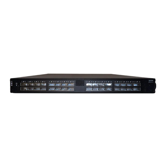
40GbE versions) are offered, in addition, with Cumulus Linux support, as an alternative operating system. For a full list of all available ordering options, see Ordering Information. SN2700 Front View SN2740 Front View SN2410 Front View SN2100 Front View Mellanox Technologies... -
Page 11: Speed And Switching Capabilities
SN2010 Rear View 2.1 Speed and Switching Capabilities The table below describes maximum throughput and interface speed per system model. System Model 10/25GbE SFP28 Interfaces* 40/50/56/100GbE QSFP28 Interfaces* Max Throughput SN2700 6.4Tb/s (using QSFP to SFP splitter cables) Mellanox Technologies... -
Page 12: Management Interfaces, Psus And Fans
> Ethernet Switch Systems, and select the desired product page. 2.4 Certifications The list of certifications (such as EMC, Safety and others) per system for different regions of the world is located on the Mellanox website at http://www.mellanox.com/page/environmental_compliance. Mellanox Technologies... -
Page 13: Installation
Safety warnings are provided here in the English language. For safety warnings in other languages, refer to the 1U Switch Installation Safety Instructions document available on mellanox.com. Safety Warnings (English) Installation Instructions Read all installation instructions before connecting the equipment to the power source. Bodily Injury Due to Weight Mellanox Technologies... - Page 14 During periods of lightning activity, do not work on the equipment or connect or disconnect cables. Copper Cable Connecting/Disconnecting Copper cables are heavy and not flexible, as such they should be carefully attached to or detached from the connectors. Refer to the cable manufacturer for special warnings/instructions. Mellanox Technologies...
- Page 15 Caution: Slide/rail mounted equipment is not to be used as a shelf or a work space. The rails are not intended for sliding the unit away from the rack. It is for permanent installation at final resting place only, not used for service and maintenance Mellanox Technologies...
-
Page 16: Air Flow
The table below provides an air flow color legend and respective OPN designation. Direction Description and OPN Designation Connector side inlet to power side outlet. Red latches are placed on the power inlet side. OPN designation is “-R”. Mellanox Technologies... -
Page 17: Package Contents
3.6 SN2700 Static Rail Kit Kit OPN Rack Size and Rack Depth Range MTEF-KIT-A Short (17”-24”) or Standard (24”-34”) The following parts are included in the static rail kit (see figure below): • 2x Rack mount rails (A) Mellanox Technologies... - Page 18 • The FRU side is extractable. Mounting the rack brackets inverted to the FRU side (Option 2) will allow you to slide the FRUs, in and out. Installation Option 1 & Option 2 Mellanox Technologies...
- Page 19 Attach the left and right rack mount rails (A) to the switch, by gently pushing the switch chassis’ pins through the slider key holes, until locking occurs. Secure the chassis in the rails by screwing 2 flat head Phillips screws (E) in the designated points with a torque of 1.5±0.2 Mellanox Technologies...
- Page 20 Mount the system into the rack enclosure, and attach the brackets installed on the system to the rack’s posts. Secure the brackets to the rack’s posts by inserting four M6 screws in the designated cage nuts, as described in the figure below. Do not tighten the screws yet. Mellanox Technologies...
-
Page 21: Removing The System From The Rack
The following parts are included in the rail kit package (see figure below): • 1x Right inner rail (A) +2x Outer rails (C) - Bundled • 1x Left inner rail (B) + 2x Outer rails (D) - Bundled Mellanox Technologies... - Page 22 While planning how to place the system, review the following points: • Make sure the system air flow is compatible with your installation selection. It is important to keep the airflow within the rack in the same direction. Mellanox Technologies...
- Page 23 Attaching the Inner Rails Secure the chassis in the inner rails by screwing the 2 flat head Phillips screws (F) in the designated points with a torque of 1.5±0.2 Nm. Securing the Chassis in the Inner Rails Mellanox Technologies...
-
Page 24: Removing The System From The Rack
Pull the unit out until braking is felt. For safety purposes, the locking mechanism will not allow a complete removal of the unit at this stage. Pulling the Unit Outwards Press on the locking spring (appears in red in the figure below) on both sides simultaneously, and continue pulling the unit towards you until it is fully removed. Mellanox Technologies... -
Page 25: Sn2740/Sn2410 Static Rail Kit
Before mounting the system to the rack, select the way you wish to place the system. Pay attention to the airflow within the rack cooling, connector and cabling options. While planning how to place the system, consider the two installation options shown in the Installation Options figure below, and review the following points: Mellanox Technologies... - Page 26 Attach the left and right rack mount rails (A) to the switch, and secure the chassis in the rails by screwing 2 flat head Phillips screws (D) in the designated points on each side (a total of 4 screws). To tighten the screws, use a torque of 1.5±0.2 Nm. Attaching the Rails to the Chassis Mellanox Technologies...
-
Page 27: Sn2100/Sn2010 Side By Side Mounting Rail Kit
The following parts are included in the rail kit (see figure below): • 1 metal frame for two systems (A) • 2 system mounting blades with 8 screw holes - the kit contains enough rails to install 2 systems (B) Mellanox Technologies... - Page 28 Carefully position the SE (single ended) cables one on top of the other, and use three cable ties to pair them together (shown in figure). While pairing the cables, make sure the cables are paired in symmetry to the switch, in order to avoid damaging the cables. Coupling the Cables with Cable-ties Mellanox Technologies...
- Page 29 Screw the right blade with eight 4-40 flathead screws, and the left blade with seven 4-40 flathead screws. The recommended torque is 0.49-0.54 Nm. Attach the Blades to the System Attached Rail with Threaded Cables - Top View Mellanox Technologies...
- Page 30 Attach the frame to the rack by using ten spacer cage nuts, and screw ten M6 pan head screws - four in the front part of the rack, and 6 in its rear part. The recommended torque is 6.55-7.35 Nm. See figure above. Place the frame in the cabinet. Attaching the Frame to the Rack Mellanox Technologies...
-
Page 31: Sn2100/Sn2010 Static Single Switch Rail Kit
This section is relevant to short-depth systems that allow such form of installation only. Kit OPN Rack Size and Rack Depth Range MTEF-KIT-E Rack installation static kit for SN2100/SN2010 systems short depth 1U half-width switches, allows installation of a single switch into standard depth racks. Mellanox Technologies... - Page 32 While your installation partner is supporting the system’s weight, perform steps 3 and 4: On the rear side of the cabinet, install the two blades (F) in the selected rack unit, using four M6 screws and washers (C+D+E). Do not tighten the screws yet. Mellanox Technologies...
-
Page 33: Cable Installation
Do not force the cable into the cage with more than 40 newtons / 9.0 pounds / 4kg force. Greater insertion force may cause damage to the cable or to the cage. SN2700, SN2100 and SN2010 QSFP Cable Orientation Mellanox Technologies... - Page 34 SN2010 SFP Cable Orientation SN2740 Cable Orientation SN2410 Cable Orientation Mellanox Technologies...
-
Page 35: Splitter (Breakout) Cables And Adapters
The top QSFP28 ports marked in green are splittable to 4 SFP28 ports, each. The bottom QSFP28 ports (gray) are blocked when the upper ports are in split mode. All QSFP28 ports can be split to 2 QSFP28 ports. Mellanox Technologies... -
Page 36: Sn2410 Splitting Options
All QSFP28 ports are splittable. Each port can be split into 4xSFP28 (10/25G) or 2xQSFP28 (50G) ports. There are no blocking requirements. 3.11.1.6 SN2010 Splitting Options All QSFP28 ports are splittable. Each port can be split into 4xSFP28 (10/25G) or 2xQSFP28 (50G) ports each. There are no blocking requirements. Mellanox Technologies... -
Page 37: Initial Power On
System Status LEDs 5 Minutes After Power On in SN2700 Power On in SN2740 Power On in SN 2410 System Status LEDs 5 Minutes After Power On in SN2100 System Status LEDs 5 Minutes After Power On in SN2010 Mellanox Technologies... -
Page 38: System Bring-Up
Step 2. Configure a serial terminal program (for example, HyperTerminal, minicom, or Tera Term) on your host PC with the settings described in the table below. Once you perform that, you should get the CLI prompt of the system. Serial Terminal Program Configuration Parameter Setting Baud Rate 115200 Data bits Stop bits Parity None Mellanox Technologies... - Page 39 Either press <Enter> to save changes and exit, or enter the or hit <enter> to save changes and exit. configuration step number that you wish to return to. Choice: <Enter> Note: To re-run the configuration wizard, run the command Configuration changes saved. “configuration jump-start” in Config mode. Mellanox Technologies...
- Page 40 Launching CLI... Step 5. Before attempting a remote (for example, SSH) connection to the system, check the mgmt0 interface configuration. Specifically, verify the existence of an IP address. To check the current mgmt0 configuration, enter the following command: Mellanox Technologies...
-
Page 41: Disable Dynamic Host Configuration Protocol (Dhcp)
<localhost># ssh admin@<ip-address> Mellanox Onyx (MLNX-OS) Switch Management Password: Mellanox Switch Mellanox configuration wizard Do you want to use the wizard for initial configuration? yes Step 1: Hostname? [my-switch] Step 2: Use DHCP on mgmt0 interface? [yes] no <localhost># Mellanox Technologies... -
Page 42: Remote Connection With Mellanox Onyx (Mlnx-Os)
For power supply unit air flow direction, refer to Flow. To extract a power supply unit: The power supply slots of SN2740 and SN2410 should not be left empty for more than 5 minutes. Remove the power cord from the power supply unit. Mellanox Technologies... -
Page 43: Fans
The green Fan Status LED should light. If not, extract the fan unit and reinsert it. After two unsuccessful attempts to install the fan unit, power off the system before attempting any system debug. Fan Module Latches Mellanox Technologies... - Page 44 Mellanox Technologies...
-
Page 45: Interfaces
4.5W high power modules are supported on Mellanox Onyx (MLNX-OS) from version 3.6.3004 onwards. b. 5.0W high power modules are supported on Mellanox Onyx (MLNX-OS) from version 3.x.1xxx onwards for 100GbE Fiber Optics up to 80km. c. SFP28 ports. Using 5.0W Modules on Ports 49, 50, 55, 56 in SN2410M/SN2410bM Mellanox Technologies... -
Page 46: Supported Passive Cables In Sn2010Bm
(100MbE to 1GbE). The management ports’ network attributes (such as IP address) need to be pre-configured via the RS232 serial console port or by DHCP before use. Refer to Configuring Network Attributes Using Mellanox Onyx (MLNX-OS) to view the full procedure. Mellanox Technologies... -
Page 47: Usb
4.7 Status and Port LEDs Notifications. 4.8 LED Notifications The system’s LEDs are an important tool for hardware event notification and troubleshooting. LEDs Symbols Symbol Name Description Normal Conditions System Status LED Shows the health of the system. Green/Flashing green when booting Mellanox Technologies... -
Page 48: System Status Led
Both of the System Status LEDs (front and back, if exist) supply identical information. System Status LEDs - Front and Rear Sides in SN2700 Front Panel Description Rear Panel Both of these LEDs in the red ovals show the system’s status. System Status LEDs - Front Side in SN2740 Mellanox Technologies... - Page 49 It may take up to five minutes to turn on the system. If the System Status LED shows red after five minutes, unplug the system and call your Mellanox representative for assistance. System Status LED Assignments LED Behavior Description Action Required Solid Green The system is up and running normally. Mellanox Technologies...
-
Page 50: Fan Status Led
Fan Status LED in SN2410 - Front and Rear Sides Both of these LEDs in the red ovals show the fans’ status. Fan Status LED in SN2100 The SN2100 systems have a front fan LED only. Fan Status LED in SN2010 Mellanox Technologies... -
Page 51: Power Supply Status Leds
The following information does not apply to the SN2100/SN2010 systems. In these systems, the power supply units are non- replaceable, and there is a designated LED for each unit in the system’s front panel. (Front panel figures are located in the Introduction.) Power Status LED Mellanox Technologies... - Page 52 PSU might be faulty. PSU not present The power supply status LEDs on the rear side of the system (in SN2700, SN2740 and SN2410 only) are located on the PSUs themselves. Each PSU has one LED of its own. Mellanox Technologies...
-
Page 53: Unit Identification Led
To deactivate the UID LED on a switch system, run: switch (config) # led MGMT uid off 4.8.5 Bad Port LED The Bad Port LED indicator is used to indicate symbol errors in one or more system ports. Mellanox Technologies... -
Page 54: Port Leds
If the ports run at a 25GbE/10GbE speed each, all LEDs may light green, according to the selected lane. Port LEDs in Ethernet System Mode LED Behavior Description Action Required Link is down. Check the cable Solid Green Link is up with no traffic. Mellanox Technologies... -
Page 55: Inventory Information
In some systems, there is no pull-out tab, and the information is provided on labels in several locations. SN2700 Pull-out Tab SN2740 Inventory Information Illustration SN2410 Inventory Information Illustration Mellanox Technologies... - Page 56 SN2100 Pull-out Tab SN2010 Pull-out Tab Mellanox Technologies...
-
Page 57: Software Management
The systems do not require firmware updating. Firmware updating is done through the Mellanox Onyx (MLNX-OS) management software. 5.1.3 Cumulus Linux Software Upgrade For Cumulus Linux software upgrade instructions, see Upgrading Cumulus Linux in the Cumulus Linux User Guide. Mellanox Technologies... -
Page 58: Troubleshooting
Replace the fan FRU if needed (possible in SN2700, SN2740 and SN2410 only) PSU Status LED is red Cause: Possible PSU issue Solution: • Check/replace the power cable • Replace the PSU if needed (possible in SN2700, SN2740 and SN2410 only) Mellanox Technologies... - Page 59 " • Select previous image to boot by pressing an arrow key and choosing the appropriate image. Cumulus Linux System boot failure while using Software upgrade failed on x86 Monitoring and Troubleshooting Cumulus Linux based systems User Guide Mellanox Technologies...
-
Page 60: Specifications
Safety/ EMC: CB, cTUVus, CE, CU, S_Mark, CE, FCC, VCCI, ICES, RCM, BSMI, KCC, CCC RoHS: RoHS complaint Power Supply Input Voltage: 100-127VAC; 50/60Hz 3.5A; 200-240 50/60Hz 2.9A/ 192-288VDC (not certified) AC and DC 48VDC (Input voltage 40-72 VDC) Mellanox Technologies... -
Page 61: Sn2740 Series
1 PSU: 10.23kg, 2 PSUs: 11.1kg Speed: 10/25/40/50/56/100GbE per port Connector cage: 32 QSFP28 Environmental Temperature: Operational: 0° to 40°C Non-Operational: -40° to 70°C Humidity: Operational: 10% - 85% non-condensing Non-Operational: 10% - 90% non-condensing Altitude: 3050m Noise level: 71.6 dB(A) Mellanox Technologies... -
Page 62: Sn2410 Series
1.72"(H) x 17.24"(W) x 15.5"(D) Mounting: 19” Rack mount Weight: 1 PSU weight 6.726kg (14.8 lb) 2 PSU weight 7.526kg (16.6 lb) Speed: 10/25GbE per port (ports 1-48), 10/25/40/50/56/100GbE per port (ports 49-56) Connector cage: 48xSFP28 and 8xQSFP28 Mellanox Technologies... - Page 63 Intel x86 1.40GHz Dual Core PCIe: 4x Gen2.0 Switch: Mellanox Spectrum Memory: 8GB DDR3 RAM, 32G SSD for systems based on Switch rev. B1 and earlier 8GB DDR3 RAM, 16G SSD for systems based on Switch rev. B2 and higher Throughput 4Tb/s Mellanox Technologies...
-
Page 64: Sn2100 Series
QSFP28 port): 216.6W 100GbE Models - Typical power with passive cables (ATIS): 94.3W Max power with optical cables (assuming 3.5W per each QSFP28 port): 248.6W Main Devices CPU: Intel x86 2.40GHz Quad Core PCIe: 4x Gen2.0 Switch: Mellanox Spectrum Mellanox Technologies... -
Page 65: Sn2010 Series
100-127VAC 50/60Hz 4.5A; 200-240 50/60Hz 2.9A Global Power Consumption: Typical power with passive cables (ATIS): 57W Max power with optical cables (assuming 3.5W per each QSFP28 port): 250W Main Devices CPU: Intel x86 2.40GHz Quad Core PCIe: 4x Gen2.0 Mellanox Technologies... - Page 66 Feature Value Switch: Mellanox Spectrum Memory: SDRAM: 8GB DDR3L 1600 MT/s SO-DIMM Storage: 16GB Dual Channel MLC M.2-SATA SSD Throughput 1.7Tb/s Mellanox Technologies...
-
Page 67: Appendixes
SN2700, SN2740, SN2410, RJ-45 SN2010, SN2100 ACC000501 Power cord Type C13-C14 SN2700, SN2740, SN2410, SN2010, SN2100 MTEF-FANF-A FAN MODULE W/ P2C air flow (front SN2700, SN2410 to rear) MTEF-FANR-A FAN MODULE W/ C2P air flow (rear SN2700, SN2410 to front) Mellanox Technologies... -
Page 68: Thermal Threshold Definitions
For thermal threshold definitions in Cumulus Linux, see Configuring Net-SNMP Event Notification Traps in the Cumulus Networks Help Center. 8.3 Interface Specifications 8.3.1 QSFP28 Pin Description QSFP Pin Description Connector Pin Number Symbol Signal Description Ground Tx2n Connected to Port 2 lane Rx Inverted Data Mellanox Technologies... - Page 69 Connected to Port 1 lane Tx Non-Inverted Data Rx1n Connected to Port 1 lane Tx Inverted Data Ground Ground Rx2n Connected to Port 2 lane Tx Inverted Data Rx2p Connected to Port 2 lane Tx Non-Inverted Data Ground Mellanox Technologies...
- Page 70 Tx3p Connected to Port 3 lane Rx Non-Inverted Data Tx3n Connected to Port 3 lane Rx Inverted Data Ground Tx1p Connected to Port 1 lane Rx Non-Inverted Data Tx1n Connected to Port 1 lane Rx Inverted Data Ground Mellanox Technologies...
-
Page 71: Sfp28 Pin Description
Description Note VeeT Module Transmitter Ground TX_Fault Module Transmitter Fault TX_Disable Transmitter Disable. Turns off transmitter laser output 2-wire Serial Interface Data Line 2-wire Serial Interface Clock Line MOD_ABS Module Absent. Grounded within the module No connection required Mellanox Technologies... -
Page 72: Rj45 To Db9 Harness Pinout
Logic 0 indicates normal operation; logic 1 indicates loss of signal. 8.3.3 RJ45 to DB9 Harness Pinout The RS232 harness cable (DB9 to RJ45) is provided within the package to connect a host PC to the system's Console RJ45 port. RJ45 to DB9 Harness Pinout Mellanox Technologies... -
Page 73: Rj45 To Rj45 Harness
8.4 Disassembly and Disposal 8.4.1 Disassembly Procedure To disassemble the system from the rack: Unplug and remove all connectors. Unplug all power cords. Remove the ground wire. Unscrew the center bolts from the side of the system with the bracket. Mellanox Technologies... -
Page 74: Disposal
Dispose of this product and all of its parts in a responsible and environmentally friendly way. Follow the instructions found at http://www.mellanox.com/page/dismantling_procedures for proper disassembly and disposal of the switch, according to the WEEE directive. Mellanox Technologies... -
Page 75: Document Revision History
Updated “MLNX-OS” to “Onyx (MLNX-OS)” throughout the document December 2017 Minor format updates Updated "High Power/LR4 Transceivers Support” October 2017 Added SN2740 Updated: • “Installation Kit” • “System Installation and Initialization” • “SN2410 Splitting Options” February 2017 Updated "Unit Identification LED” Mellanox Technologies... - Page 76 Added "Taiwan BSMI Class A Statement in Safety Warnings" Updated: • “Introduction to Mellanox SN2000 Spectrum™ Ethernet Switch Systems” • “Software Management” • “Troubleshooting Instructions” • “Specifications” • “Accessory and Replacement Parts” December 2015 Added SN2410 August 2015 First revision Mellanox Technologies...
Need help?
Do you have a question about the Spectrum SN2700 and is the answer not in the manual?
Questions and answers