Mellanox Technologies SN2700 Hardware User Manual
1u switch systems
Hide thumbs
Also See for SN2700:
- Hardware user manual (130 pages) ,
- User manual (76 pages) ,
- Quick installation manual (8 pages)

Related Manuals for Mellanox Technologies SN2700


Summary of Contents for Mellanox Technologies SN2700
- Page 1 Mellanox 1U Switch Systems Hardware User Manual Models: SN2700 and SN2410 Rev 1.2 www.mellanox.com...
- Page 2 KIND AND SOLELY FOR THE PURPOSE OF AIDING THE CUSTOMER IN TESTING APPLICATIONS THAT USE THE PRODUCTS IN DESIGNATED SOLUTIONS. THE CUSTOMER'S MANUFACTURING TEST ENVIRONMENT HAS NOT MET THE STANDARDS SET BY MELLANOX TECHNOLOGIES TO FULLY QUALIFY THE PRODUCT(S) AND/OR THE SYSTEM USING IT. THEREFORE, MELLANOX TECHNOLOGIES CANNOT AND DOES NOT GUARANTEE OR WARRANT THAT THE PRODUCTS WILL OPERATE WITH THE HIGHEST QUALITY.
-
Page 3: Table Of Contents
2.4 Mounting Options ..........18 2.4.1 19” Systems Mounting - Static Rail-Kit for SN2700 ..... . 18 2.4.2 19”... - Page 4 6.1 SN2700 Series ........
- Page 5 SN2700 and SN2410 Rear Side View ........
- Page 6 Figure 43: SN2700 Pull-out Tab ........
- Page 7 SN2700 Specifications ........
-
Page 8: Revision History
“Introduction to Mellanox SN2XXX Spectrum™ Ethernet Switch Systems” • “Software Management” • “Troubleshooting Instructions” • “Specifications” • “Accessory and Replacement Parts” Added: • Taiwan BSMI Class A Statement in “Safety Warnings (Multiple Languages)” December 2015 Added SN2410 August 2015 Initial revision Mellanox Technologies... -
Page 9: About This Manual
(ONIE) Quick Start Guide Conventions The following icons are used throughout this document to indicate information that is important to the user. This icon makes recommendations to the user. This icon indicates information that is helpful to the user. Mellanox Technologies... - Page 10 Rev 1.2 This icon indicates a situation that can potentially cause damage to hardware or software. This icon indicates a situation that can potentially cause personal injury. Mellanox Technologies...
-
Page 11: Chapter 1 Introduction To Mellanox Sn2Xxx Spectrum
(ONIE) for zero touch installations of network operating systems. While all Ethernet systems can be purchased preloaded with Mellanox-OS, the SN2700 and SN2410 switches (in both the 100GbE and the 40GbE versions) are offered, in addition, with Cumulus Linux support, as an alternative operating system. -
Page 12: Speed And Switching
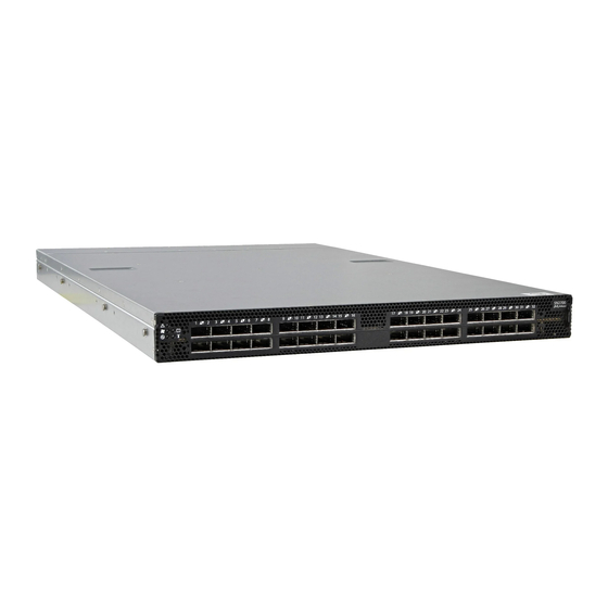
Introduction to Mellanox SN2XXX Spectrum™ Ethernet Switch Systems Figure 1: SN2700 Front Side View Figure 2: SN2410 Front Side View Figure 3: SN2700 and SN2410 Rear Side View Speed and Switching Table 3 describes maximum throughput and interface speed per system model. -
Page 13: Features
Flow”. Table 5 - Ordering Part Numbers (OPNs) System Description Model SN2700 MSN2700-CS2F Spectrum™ based 100GbE 1U Open Ethernet Switch with MLNX- OS, 32 QSFP28 ports, 2 Power Supplies (AC), Standard depth, x86 CPU, P2C airflow, Rail Kit, RoHS6 MSN2700-CS2R Spectrum™... - Page 14 (AC), x86 dual core, Short depth, P2C airflow, Rail Kit, RoHS6 MSN2410-CB2RC Spectrum™ based 25GbE/100GbE 1U Open Ethernet switch with Cumulus Linux, 48 SFP28 ports, 8 QSFP28 ports, 2 power supplies (AC), x86 dual core, Short depth, C2P airflow, Rail Kit, RoHS6 Mellanox Technologies...
-
Page 15: Chapter 2 Installation
безопасности при установке (Russian),” on page • For Safety Warnings in Romanian, see Section E.9, “Avertismente privind siguranţa la instalare (Romanian),” on page • For Safety Warnings in Croatian, see Section E.10, “Sigurnosna upozorenja za instali- ranje (Croatian),” on page Mellanox Technologies... -
Page 16: Air Flow
Ending with Connector side inlet to power side outlet. “-R” Red latches are placed on the power inlet side. Ending with Power side inlet to connector side outlet. “-F” Blue latches are placed on the power inlet side. Mellanox Technologies... -
Page 17: Package Contents
Before installing your new system, unpack it and check against the parts list below that all the parts have been sent. Check the parts for visible damage that may have occurred during shipping. The SN2700 and SN2410 package content is as follows: • 1 – System •... -
Page 18: Mounting Options
Mounting Options If anything is damaged or missing, contact your sales representative at support@mella- nox.com. By default, the SN2700 system is sold with the Static Rail-kit described in Section 2.4.1. The SN2410 system is sold with the Static Rail-kit described in Section 2.4.3. -
Page 19: Figure 6: Rack Rail Kit Parts
2) will determine the system’s adjustable side. The system’s part to which the brackets are attached will be adjacent to the cabinet. • The FRU side is extractable. Mounting the rack brackets inverted to the FRU side (Option 2) will allow you to slide the FRUs, in and out. Mellanox Technologies... -
Page 20: Figure 7: Installation Options
Secure the system in the brack- ets by screwing the remaining 2 flat head Phillips screws (E) in the designated points with a torque of 1.5±0.2 Nm. See Figure Mellanox Technologies... -
Page 21: Figure 9: Attaching The Brackets To The Chassis
Mount the system into the rack enclosure, and attach the brackets installed on the system to the Step 5. rack’s posts. Secure the brackets to the rack’s posts by inserting four M6 screws in the desig- nated cage nuts, as described in Figure 11. Do not tighten the screws yet. Mellanox Technologies... -
Page 22: Figure 11: Attaching The Brackets To The Rack
Loosen the screws attaching the blades to the rack, and pull the blades towards you, while your Step 3. partner is holding the system. Extract the loosened screws from Step 2 and dismount the system from the rack. Step 4. Remove the rails and brackets from the chassis by unscrewing 8 screws. Step 5. Mellanox Technologies... -
Page 23: 19" Systems Mounting- Telescopic Rail-Kit For Sn2700
Installation Rev 1.2 2.4.2 19” Systems Mounting- Telescopic Rail-Kit for SN2700 Note: the Telescopic Rail-Kit is not included in the system’s package, and can be pur- chased separately. There are two installation kit options: • Standard depth systems should be mounted using the standard rail kit. -
Page 24: Figure 13: Rack Rail Kit Parts
1. Extend the rail assembly by pulling the extension outwards (D). 2. Extract rail A from rail C by pushing it outside from the rear part of the assembly. To allow com- plete separation of rail A from rail C, press the quick-release latch. Mellanox Technologies... -
Page 25: Figure 15: Installing The Cage Nuts
If cable accommodation is required, route the power cable and/or Eth cable through either of Step 3. the outer rails. Attach the switch to the left and right inner rails (A+B), by gently pushing the switch chassis’ Step 4. pins through the slider key holes, until locking occurs. Mellanox Technologies... -
Page 26: Figure 17: Attaching The Inner Rails To The Chassis
1.5±0.2 Nm. Figure 18: Securing the Chassis in the Inner Rails Slide the switch into the rack by carefully pushing the inner rails into the outer rails installed on Step 6. the rack. Mellanox Technologies... -
Page 27: Figure 19: Sliding The Switch Into The Rack
Step 2. the rack. Pull the unit out until braking is felt. For safety purposes, the locking mechanism will not allow Step 3. a complete removal of the unit at this stage. Figure 20: Pulling the Unit Outwards Mellanox Technologies... -
Page 28: 19" Systems Mounting - Static Rail-Kit For Sn2410
Short (15.7"-23.6" \ 40 to 60 cm) MTEF-KIT-SP Standard (23.6"-31.5" \ 60 to 80 cm) • 2x Rack mount rails (A) • 2x Rack mount blades (B) • 8x M6 Standard cage nuts¹ ² and 8x M6 Standard pan-head Phillips screws¹ (C) Mellanox Technologies... -
Page 29: Figure 22: Rack Rail Kit Parts
3.5" (8.9 cm), by optional placement of the system’s rails. • The FRU side is extractable. Mounting the rack blades inverted to the FRU side (Option 2) will allow you to slide the FRUs, in and out. Mellanox Technologies... -
Page 30: Figure 23: Installation Options
4 cage nuts in the extractable side. Note that while each rack U (unit) consists of three holes, the cage nut should be installed vertically with its ears engaging the top and bottom holes only. See Figure Mellanox Technologies... -
Page 31: Figure 25: Installing The Cage Nuts
M6 screws (D) to fix the blades into the rack. Do not tighten the screws yet. See Figure Figure 27: Sliding the Blades in the Rails Secure the system in the rack by tightening the 8 screws inserted in Step 3 and Step 4 with a Step 5. torque of 4.5±0.5 Nm. Mellanox Technologies... -
Page 32: Cable Installation
Splitting a 100GbE QSFP28 port to 4 separate 25GbE ports (using a breakout cable) disables (unmaps) the 100GbE port below it. See Figure 30,“SN2700 Splitting Options”. 2.5.1.1 Using Breakout Cables with MLNX-OS When using this feature, you should log into the MLNX-OS® CLI and configure the individual ports to be ‘split-2’... -
Page 33: Figure 29: Breakout Or Fanout Cables
Figure 29: Breakout or Fanout Cables 2.5.1.3 SN2700 Splitting Options Figure 30: SN2700 Splitting Options The top QSFP ports marked in green are splittable to 4 SFP ports, each. The bottom QSFP ports (gray) are blocked when the upper ports are in split mode. All QSFP ports marked in yellow can be split to 2 SFP ports. -
Page 34: Initial Power On
Check the System Status LEDs and confirm that all of the LEDs show status lights consistent Step 4. with normal operation (initially flashing, and then moving to a steady color) as shown in Figure 32 below. For more information, refer to “LEDs”. Mellanox Technologies... -
Page 35: System Bring-Up
Since the system comes with a pre- configured DHCP, you may find the explanation in Section 2.7.1.1 sufficient. In case a manual configuration is required, please refer to the instructions in Section 2.7.1.2. Mellanox Technologies... -
Page 36: Table 10: Serial Terminal Program Configuration
Login as admin and use admin as password. On the first login, the MLNX-OS configuration Step 3. wizard will start. To configure network attributes and other initial parameters to the system, follow the configu- Step 4. ration wizard as shown in Table Mellanox Technologies... -
Page 37: Table 11: Configuration Wizard Session
To change an answer, enter the step number to return to or hit Note: <enter> to save changes and exit. To re-run the configuration wizard, run the command “configura- Choice: <Enter> tion jump-start” in Config mode. Configuration changes saved. Mellanox Technologies... -
Page 38: Table 12: Configuration Wizard Session - Static Ip Configuration
To change an answer, enter the step number to return to. Otherwise hit <enter> to save changes and exit. Choice: Configuration changes saved. To return to the wizard from the CLI, enter the “configuration jump-start” command from configure mode. Launching CLI... > Mellanox Technologies... - Page 39 Set up an Ethernet connection between the system and a local network machine using a stan- Step 1. dard RJ45 connector. Start a remote secured shell (SSH) using the command: “ssh -l <username> <IP_address>”, Step 2. # ssh -l <username> <ip_address> Mellanox Technologies...
-
Page 40: Configuring Network Attributes Using Cumulus Linux
Grasping the handle with your hand, push the latch release with your thumb while pulling the Step 2. handle outward. As the power supply unit unseats, the power supply unit status LEDs will turn off. Remove the power supply unit. Step 3. Mellanox Technologies... -
Page 41: Fans
Make sure that the fans have the air flow that matches the model number. An air flow opposite to the system design will cause the system to operate at a higher (less than optimal) temperature. For power supply unit air flow direction, refer to Section 2.2 on page Mellanox Technologies... -
Page 42: Figure 35: Fan Module Latches
The green Fan Status LED should light. If not, extract the fan unit and reinsert it. After system two unsuccessful attempts to install the fan unit, power off the before attempt- ing any system debug. Figure 35: Fan Module Latches Mellanox Technologies... -
Page 43: Chapter 3 Software Management
The Ethernet ports for remote management connect to Ethernet systems. These sys- tems must be configured to 100Mb/1Gb auto-negotiation. 3.1.2 Cumulus Linux Software Upgrade For Cumulus Linux software upgrade instructions, see Upgrading Cumulus Linux in the Cumu- lus Linux User Guide. Mellanox Technologies... -
Page 44: Chapter 4 Interfaces
The two RJ45 Ethernet ports labeled “MGT” provide access for remote management. The management ports are configured with auto-negotiation capabilities by default (100MbE to 1000GbE). The management ports’ network attributes (such as IP address) need to be pre-config- Mellanox Technologies... -
Page 45: Usb
To reset the system, the CPU of its management board and the “admin” password, push the reset button and keep it pressed for at least 15 seconds. You will then be able to enter without a pass- word and set a new password for the user “admin”. Mellanox Technologies... -
Page 46: Leds
The right figure reflects the system status LEDs in SN2700. For SN2410, see Figure 37. In SN2410, the system status LEDs in the front panel are located above the LEDs of the SFP ports. -
Page 47: Table 14: System Status Led Assignments
Mellanox representa- tive for assistance. 4.2.1.2 Fan Status LED Figure 38: Fan Status LED - Front and Rear Sides Both of these LEDs in the red ovals show the fans’ status. Mellanox Technologies... -
Page 48: Table 15: Fan Status Front Led Assignments
In case the power supply is an FRU, a second power supply unit can be added to support hot-swap ability. Each power supply unit has a single 2 color LED on the right side of the unit, that indicates the status of the unit. Mellanox Technologies... -
Page 49: Table 17: Power Supply Unit Status Front Led Assignments
Power supply warning events where the power Call your Mellanox representative for supply continues to operate; high temp, high assistance. power, high current, slow fan. No AC power to all power supplies. Call your Mellanox representative for assistance. Mellanox Technologies... -
Page 50: Table 19: Bad Port Led Assignments
Error, one or more ports have received symbol Check symbol error counters on the sys- errors. tem UI to identify the ports. Possible causes are: Replace the cable on these ports. • Bad cable • Bad connection • Bad connector Mellanox Technologies... -
Page 51: Table 20: Port Leds In Ethernet System Mode
Interfaces Rev 1.2 4.2.1.6 Port LEDs Figure 41: SN2700 Port LEDs Figure 42: SN2410 SFP28 Port LEDs Figure 43: SN2410 QSFP28 Port LEDs The status of each pair of adjacent QSFP28 ports is indicated by four LEDs, as shown in the pic- ture above: •... -
Page 52: Inventory Information
In some systems, there is no pull-out tab, and the information is provided on labels in sev- eral locations. Figure 44: SN2700 Pull-out Tab Mellanox Technologies... - Page 53 Interfaces Rev 1.2 Figure 45: SN2410 Inventory Information Illustration Mellanox Technologies...
-
Page 54: Chapter 5 Troubleshooting
Check that the FAN is fully inserted and nothing blocks the airflow. • Replace the FAN FRU if needed. PSU Status LED is red This state is indicative of a problem with the PSU. • Check/replace the power cable. • Replace the PSU if needed. Mellanox Technologies... - Page 55 Highlighted entry is 0: " • Select previous image to boot by pressing an arrow key and choosing the appropriate image. System boot failure Monitoring and Troubleshooting Cumulus Linux while using Cumu- User Guide. lus Linux Mellanox Technologies...
-
Page 56: Chapter 6 Specifications
Rev 1.2 Specifications Specifications SN2700 Series Table 22 - SN2700 Specifications Feature Value Mechanical Size: Standard - 1.7” (H) x 16.85” (W) x27” (D), 43.6mm (H) x 428mm (W) x 685.8mm (D) Mounting: 19” Rack mount Mounting: 19” Rack mount Weight: 1 PSU: 10.23kg... - Page 57 Specifications Rev 1.2 Table 22 - SN2700 Specifications Feature Value Switching Capacity: 6.4Tb/s Mellanox Technologies...
-
Page 58: Sn2410 Series
Typical power with passive cables (ATIS): 165W Max power with optical cables (assuming 3.5W per each QSFP port, and 1.5W per each SFP port): 362W Main Devices CPU: Intel Celeron 1047UE (x86) Switch: Mellanox Spectrum™ Memory: 8GB DDR3 RAM 32GB SSD Switching Capacity: 4Tb/s Mellanox Technologies... -
Page 59: Appendix A Accessory And Replacement Parts
460W AC Power Supply w/ front to rear air flow HAR000028 Harness RS232 2M cable – DB9 to RJ-45 ACC000501 Power cord Type C13-C14 MTEF-FANF-A Fan module w/rear to front airflow MTEF-FANR-A Fan module w/front to rear airflow fan for SX67X0/SX1710 switch systems Mellanox Technologies... -
Page 60: Appendix B Thermal Threshold Definitions
• Emergency – 130°C: In case the firmware fails to shut down the device upon crossing the Critical threshold, the device will auto-shutdown upon crossing the Emergency (130°C) threshold. For thermal threshold definitions in Cumulus Linux, see Configuring Net-SNMP Event Notification Traps in the Cumulus Networks Help Center. Mellanox Technologies... -
Page 61: Appendix C Interface Specifications
Vcc Tx +3.3 V Power supply transmitter Vcc 1 +3.3 V Power Supply LPMode Low Power Mode Ground Tx3p Transmitter Non-Inverted Data Input Tx3n Transmitter Inverted Data Input Ground Tx1p Transmitter Non-Inverted Data Input Tx1n Transmitter Inverted Data Input Mellanox Technologies... - Page 62 Rev 1.2 Figure 46: QSFP Connector Male and Female Views 18.35 View into Rear of Connector 8.50 18.35 View into Front of Cage 8.50 Mellanox Technologies...
-
Page 63: Sfp+ Interface
Rev 1.2 SFP+ Interface 56.50 13.90 Mellanox Technologies 11.85 13.60 14.80 13.70 MTSFPP-SR Module 1.55 0.50 8.50 0.60 2.55 1.80 44.95 Figure 47: Rear View of Module With Pin Placement 13.70 8.50 Mellanox Technologies... - Page 64 MOD_ABS pulls line low to indicate module is plugged in. e. LOS is open collector output. Should be pulled up with 4.7kΩ – 10kΩ on host board to a volt- age between 2.0V and 3.6V. Logic 0 indicates normal operation; logic 1 indicates loss of sig- nal. Mellanox Technologies...
-
Page 65: C.3 Rj45 To Db9 Harness Pinout
Rev 1.2 RJ45 to DB9 Harness Pinout In order to connect a host PC to the Console RJ45 port of the system, a RS232 harness cable (DB9 to RJ45) is supplied. Figure 48: RJ45 to DB9 Harness Pinout Mellanox Technologies... -
Page 66: Appendix D Disassembly And Disposal
(EEE) should be collected separately and not disposed of with regular household waste. Dispose of this product and all of its parts in a responsible and environmentally friendly way. Follow the instructions found at http://www.mellanox.com/page/dismantling_procedures proper disassembly and disposal of the switch, according to the WEEE directive. Mellanox Technologies... -
Page 67: Appendix E Safety Warnings (Multiple Languages)
5. Over-temperature This equipment should not be operated in an area with an ambient temperature exceed- ing the maximum recommended: 45°C (113°F). Moreover, to guarantee proper , allow at least 8cm (3 inches) of clearance around the ventilation openings. Mellanox Technologies... - Page 68 When this product is mounted or serviced in a rack, special precautions must be taken to ensure that the system remains stable. In general you should fill the rack with equip- ment starting from the bottom to the top. Mellanox Technologies...
- Page 69 This device must be installed according to the latest version of the country national electrical codes. For North America, equipment must be installed in accordance to the applicable requirements in the US National Electrical Code and the Canadian Electri- cal Code. Mellanox Technologies...
-
Page 70: ( אזהרות בטיחות בהתקנהHebrew)
Dispose of this product and all of its parts in a responsible and environmentally friendly way. 24. Country of Norway Power Restrictions This unit is intended for connection to a TN power system and an IT power system of Norway only. ( אזהרות בטיחות בהתקנהHebrew) 1. הוראות התקנה Mellanox Technologies... - Page 71 חבלת גוף כתוצאה מנשיאת משקל יתר <40 lbs 70 - 121 lbs >121 lbs 40 - 70 lbs <18 kgs 32 - 55 kgs >55 kgs 18 - 32 kgs ציוד כבד !סכנת התחשמלות 6. התחממות יתר ערימת המערכת Mellanox Technologies...
- Page 72 חיבור ספק כוח נוסף -סכנת חשמל מספר שקעים חשמליים 10. בעת סופות ברקים - סכנת חשמל 11. חיבור או ניתוק של כבלי נחושת 12. הרכבה על גבי מדף בארון 13. התקנת המוצר Mellanox Technologies...
- Page 73 Rev 1.2 14. השלכת פסולת 15. תקנות חשמל מקומיות ולאומיות 16. כבל אספקת חשמל 17. תקנות התקנה חיבור בין מערכות 19. הגנה מפני מתח גבוה Mellanox Technologies...
-
Page 74: 安裝安全性警告 (Chinese)
21. WEEE תקנת 22. מגבלות חשמליות בנורבגיה 安裝安全性警告 (Chinese) 1. 安裝指示 本設備附有備援電源供應器或在適當位置配有空白蓋板。 2. 因重量導致的人身受傷 為了安全起見,請安排足夠的人員以合力抬起本產品。 <40 lbs 70 - 121 lbs >121 lbs 40 - 70 lbs <18 kgs 32 - 55 kgs >55 kgs 18 - 32 kgs Mellanox Technologies... - Page 75 4. 有觸電的危險 有觸電的危險! 拆除風扇模組後,即可接觸到模組空腔內的電源針腳。 請勿將工具或機身零件插入到風扇模組空腔內。 5. 溫度過高 本設備不應在超過所建議的最高環境溫度的區域中運作:45°C (113°F)。此外, 為了保證氣流的流通正常,請在通風口旁保留至少 8 公分 (3 英吋 ) 的間距。 6. 堆疊機箱 機箱不應堆疊在任何其他設備上。如果機箱掉落,可能造成人員受傷與設備損 壞。 7. 複式電源連接時的電擊危險 本設備附有備援電源供應器或在適當位置配有空白蓋板。如果是電源供應器空 白蓋板,在空白蓋板已取下或未牢牢固訂的情況下,請勿操作本產品。 8. 雙極 / 中性保險絲 本系統具有雙極 / 中性保險絲。請拔掉所有電源線後,再打開本產品的蓋板或 碰觸任何內部零件。 9. 多電源輸入座 電擊與能源危害的危險。 所有 PSU 均各自獨立。 將所有電源供應器斷電,確保交換器平台內部在電源關閉狀態。 Mellanox Technologies...
- Page 76 10. 閃電時的電擊危險 在閃電期間,不要使用本設備或連接或拔下纜線。 11. 機架安裝與維修 此產品已安裝在機架中或在機架中維修時,必須採取特定預防措施以確保系統 維持穩定。一般您應該將設備從底部到頂端放滿機架。 12. 設備安裝 本設備僅限由經過訓練與 / 或合格的人員安裝、更換或維修。 13. 設備棄置 棄置本設備應遵照所有國內法規。 14. 當地與國家電氣法規 請遵照當地與國家電氣法規安裝本設備。 15. 安裝法規 請務必遵循最新版的國家電氣法規,安裝本設備。在北美地區,請務必遵循美 國國家電工法規和加拿大電工法規中的適用規定,安裝本設備。 16. 更換電池 警告:只能以 UL 認可電池,且取得最大異常充電電流低於 4mA 認證的電池進 行更換。 若更換錯誤類型的電池,會有爆炸的危險。 請依據指示棄置廢電池。 Mellanox Technologies...
- Page 77 請務必遵循最新版的國家電氣法規,安裝本設備。在北美地區,請務必遵循美 國國家電工法規和加拿大電工法規中的適用規定,安裝本設備。 20. 互連設備 連接至 RS232 設備和乙太網路介面的纜線必須是 UL 認證類型 DP-1 或 DP-2。 ( 請注意位於非 LPS 電路時 ) 過電流保護:準備好使用的列名分支電路過電流保護裝置最大額定值 20 A 必須 整合在配線中。 21. 切換開關不可用作機架或工作空間 小心:滑軌 / 導軌安裝設備不可用作機架或工作空間。導軌不適用於將設備滑 出機架使用。僅限永久安裝在最後安置區域時使用,不可用於維修和保養。 22. WEEE 指令 根據 WEEE 指令 2002/96/EC,所有廢棄的電氣與電子設備 (EEE),應分開集 中,而且不應與一般家庭廢棄物一起棄置。 請以負責和環保的方式棄置本產品及其所有零件。 Mellanox Technologies...
- Page 78 23. 挪威國家電源限制 本設備僅限連接至挪威的 TN 電源系統和 IT 電源系統。 24. China CCC Warning Statement Mellanox Technologies...
-
Page 79: Avertissements De Sécurité Pour L'installation (French)
Cet équipement ne doit pas être en service dans un local dont la température dépasse le maximum recommandé de 45°C (113°F). En outre et pour garantir une circulation d'air correcte, laisser un espace d'au moins 8 cm (3") autour des orifices de ventilation. Mellanox Technologies... - Page 80 Lors du montage ou de la maintenance de ce produit dans un rack, il faut faire spéciale- ment attention pour s'assurer que l'ensemble reste stable. En règle générale, le rack doit être rempli en commençant par le bas. Mellanox Technologies...
- Page 81 300 V, avec une gaine isolante en PVC. Le cordon doit avoir une prise moulée 250 V 10 A. 19. Courant de fuite élevé Avertissement : courant de fuite élevé, une connexion à la terre est indispensable avant de brancher l'alimentation. Mellanox Technologies...
-
Page 82: Installation Sicherheitshinweise(German)
24. Restrictions concernant l'alimentation pour la Norvège Cet appareil est prévu pour être relié à un système d'alimentation TN et un système d'alimentation informatique de Norvège uniquement. Installation Sicherheitshinweise(German) 1. Installationsanleitungen Lesen Sie alle Installationsanleitungen, bevor Sie das Gerät an die Stromversorgung anschließen. Mellanox Technologies... - Page 83 Verletzungen und Beschädigungen an Geräten führen. 7. Zweipolig/Neutrale Sicherung Achtung: Zweipolige bzw. Neutralleiter-Sicherung im Netzteil. Netzstecker ziehen, um sicher- zustellen, daß keine Spannung am Gerät anliegt. Entfernen Sie alle Netzkabel vor dem Öffnen der Abdeckung dieses Produkts oder dem Berühren der Innenteile. Mellanox Technologies...
- Page 84 13. Geräteentsorgung Die Entsorgung dieses Geräts sollte unter Beachtung aller nationalen Gesetze Bestim- mungen erfolgen. 14. Regionale und nationale elektrische Bestimmungen Dieses Gerät sollte unter Beachtung der regionalen und nationalen elektrischen Bes- timmungen installiert werden. Mellanox Technologies...
- Page 85 Kabel für den Anschluss an das Gerät RS232-und Ethernet-Schnittstellen müssen UL zertifiziert Typ DP-1 oder DP-2. (Hinweis-, wenn nicht mit Wohnsitz in LPS-Schal- tung) Überstromschutz: Eine leicht zugängliche Auflistung Abzweigleitung Überstrom- Schutzeinrichtung 20 A bewertet werden müssen in dem Gebäude Verkabelung. Mellanox Technologies...
-
Page 86: Advertencias De Seguridad De Instalación (Spanish)
>121 lbs 40 - 70 lbs <18 kgs 32 - 55 kgs >55 kgs 18 - 32 kgs 3. Equipos pesados Dado que el equipo es pesado, se debe mover únicamente mediante un elevador mecánico, para evitar lesiones. Mellanox Technologies... - Page 87 Desconecte todas las fuentes de alimentación, para asegurar que no haya corriente alguna dentro de la plataforma de conmutación. 10. Al haber rayos: peligro de descarga No utilizar el equipo ni conectar o desconectar cables durante períodos de actividad de rayos. Mellanox Technologies...
- Page 88 II y a danger d’explosion s’il y a remplacement incorrect de la batterie. Remplacer uniquement avec une batterie du même type ou d’un type équivalent recommandé par le constructeur. Mettre au rebut les batteries usagées conformément aux instructions du fabricant. Mellanox Technologies...
- Page 89 (EEE) se deben recolectar por separado y no se deben eliminar junto con residuos domésticos. Al deshacerse de este producto y de todas sus partes, hágalo de una manera respons- able y respetuosa con el medio ambiente. Mellanox Technologies...
-
Page 90: Предупреждения По Технике Безопасности При Установке (Russian)
Более того, для надлежащей вентиляции следует обеспечить зазор вокруг вентиляционных отверстий не менее 8 см (3 дюйма). 6. Установка шасси поверх другого оборудования Не устанавливать шасси поверх другого оборудования. Падение шасси может привести к травмам и повреждению оборудования. Mellanox Technologies... - Page 91 12. Установка или обслуживание в стойке При установке или обслуживании этого изделия в стойке следует обеспечить устойчивость системы. Как правило, стойка заполняется оборудованием снизу вверх. 13. Установка оборудования Устанавливать, заменять и/или обслуживать это оборудование должен только подготовленный и квалифицированный персонал. Mellanox Technologies...
- Page 92 сечением жилы не менее 1,0 мм², рассчитанного на номинальное напряжение 300 В, с ПВХ оболочкой. Шнур должен иметь литую вилку, рассчитанную на 250 В, 10 А. 19. Высокий ток утечки Осторожно! Высокий ток утечки. Заземлить перед подключением к электропитанию. Mellanox Technologies...
-
Page 93: Avertismente Privind Siguranţa La Instalare (Romanian)
электронного оборудования должны собираться и утилизироваться отдельно от обычных бытовых отходов. Следует утилизировать это изделие и все его части ответственным и экологически безопасным способом. Avertismente privind siguranţa la instalare (Romanian) 1. Instrucţiuni de instalare Citiţi toate instrucţiunile de instalare înainte de a conecta. Mellanox Technologies... - Page 94 Acest produs include o sursă de alimentare suplimentară sau un spaţiu gol în locul acesteia. În cazul în care spaţiul pentru sursa de alimentare este gol, nu operaţi produ- sul când capacul orb este îndepărtat sau nu este fixat în mod sigur. Mellanox Technologies...
- Page 95 începând de jos în sus. 13. Instalarea echipamentului Acest echipament trebuie să fie instalat, înlocuit şi/sau depanat numai de către personal instruit şi calificat. 14. Eliminarea echipamentului Eliminarea acestui echipament trebuie să se realizeze în conformitate cu toate legile şi regulamentele naţionale. Mellanox Technologies...
- Page 96 Acest dispozitiv trebuie să fie instalat în conformitate cu ultima versiune a codurilor electrice naţionale ale ţării în cauză. Pentru America de Nord, echipamentul trebuie să fie instalat conform cerințelor aplicabile din Codul electric naţional al SUA şi Codul electric canadian. Mellanox Technologies...
-
Page 97: Sigurnosna Upozorenja Za Instaliranje (Croatian)
This unit is intended for connection to a TN power system and an IT power system of Norway only. E.10 Sigurnosna upozorenja za instaliranje (Croatian) 1. Upute za instaliranje Pažljivo pročitajte upute za instaliranje prije spajanja opreme na izvor električne energije. Mellanox Technologies... - Page 98 7. Redundantno napajanje - Opasnost od električne energije Ovaj proizvod uključuje redundantno napajanje ili prazan prostor na njegovu mjestu. U slučaju praznog prostora za napajanje, nemojte rukovati proizvodom ako je pok- lopac uklonjen ili ako nije dobro pričvršćen. Mellanox Technologies...
- Page 99 13. Instaliranje opreme Ovu bi opremu trebalo instalirati, zamjenjivati i/ili servisirati samo obučeno i kvalifici- rano osoblje. 14. Odlaganje opreme Odlaganje opreme trebalo bi se vršiti sukladno nacionalnim zakonima i propisima. Mellanox Technologies...
- Page 100 Upozorenje: Veliko curenje struje; Prije spajanja napajanja nužno je spojiti uzeml- jenje. 20. Instalacijski kodovi Ovaj se uređaj mora instalirati sukladno najnovijoj verziji nacionalnih električnih kodova države. U Sjevernoj Americi oprema se mora instalirati sukladno važećim zahtjevima navedenim u US National Electrical Code i Canadian Electrical Code. Mellanox Technologies...
-
Page 101: Avvertenze Di Sicurezza Per L'installazione (Italian)
Ovaj je uređaj namijenjen samo za spajanje na električni sustav s TN uzemljenjem i na električni sustav s IT uzemljenjem države Norveške. E.11 Avvertenze di sicurezza per l’installazione (Italian) 1. Istruzioni di installazione Leggere tutte le istruzioni di installazione prima di collegare l’apparecchiatura all’alimentazione. Mellanox Technologies... - Page 102 7. Collegamento di alimentazione ridondante - Pericoli elettrici Questo prodotto è dotato di un alimentatore ridondante o, qualora esso non sia installato, di uno spazio vuoto. Qualora l’alimentatore non sia installato, non utilizzare il prodotto con il coperchio rimosso o non fissato correttamente. Mellanox Technologies...
- Page 103 13. Installazione dell’apparecchiatura Questa apparecchiatura va installata, sostituita e/o sottoposta a manutenzione solo da personale addestrato e qualificato. 14. Smaltimento dell’apparecchiatura Lo smaltimento di questa apparecchiatura va effettuato in conformità con tutte le leggi e le normative nazionali. Mellanox Technologies...
- Page 104 Questo dispositivo va installato in conformità con l’ultima versione dei codici elettrici nazionali del Paese. Per il Nord America, l’apparecchiatura va installata in conformità con i requisiti applicabili del “codice elettrico nazionale USA” e del “codice elettrico canadese”. Mellanox Technologies...
-
Page 105: Montaj Güvenlik Uyarıları (Turkish)
Questa apparecchiatura è progettata esclusivamente per il collegamento a un sistema di alimentazione TN e a un sistema di alimentazione IT. E.12 Montaj Güvenlik Uyarıları (Turkish) 1. Montaj Talimatları Ekipmanı güç kaynağına bağlamadan önce tüm montaj talimatlarını okuyun. Mellanox Technologies... - Page 106 7. Yedekli Güç Kaynaðý Baðlantýsý -Elektrik Çarpma Tehlikesi Bu ürün, yedekli güç kaynağı veya onun yerine boş elektrik kutusu içerir. Güç kaynağı için boş elektrik kutusu varsa, kutunun kapağı açıkken veya tam olarak kapatılmamışken ürünü çalıştırmayın. Mellanox Technologies...
- Page 107 Ekipmanın yalnızca eğitimli ve nitelikli personel tarafından monte edilmesi, değiştirilmesi ve/veya bakımının yapılması gerekir. 13. Ekipmanın Atılması Bu ekipmanın imhasında tüm ulusal yasalara ve düzenlemelere uyulması gerekir. 14. Yerel ve Ulusal Elektrik Kodları Bu ekipmanın montajında yerel ve ulusal elektrik kodlarına uyulması gerekir. Mellanox Technologies...
- Page 108 21. Anahtarı Raf veya Çalışma Alanı olarak kullanmayınl Dikkat: Sürgülü/raylı ekipman raf veya çalışma alanı olarak kullanılamaz. Raylar üniteyi iskeleden uzağa kaydırmak için yapılmamıştır. Sadece, ekipmanın son olarak duracağı yerdeki kalıcı montaj içindir, servis veya bakım için kullanılamaz. Mellanox Technologies...
-
Page 109: E.13 Japan Vcci Statement
(EEE) ayrı olarak toplanmalı ve evsel atıklarla birlikte çöpe atılmamalıdır. Bu ürün ve tüm parçaları çevreye dost ve sorumlu bir şekilde imha edilmelidir. 23. Norveç Güç Kısıtlamaları Bu ünite, bir TN güç sistemine ve sadece Norveç'in IT güç sistemine bağlanmak içindir. E.13 Japan VCCI Statement Mellanox Technologies...
Need help?
Do you have a question about the SN2700 and is the answer not in the manual?
Questions and answers