
Subscribe to Our Youtube Channel
Related Manuals for Mellanox Technologies Switch-IB


Summary of Contents for Mellanox Technologies Switch-IB
-
Page 1: User Manual
324-Port EDR InfiniBand Switch-IB™ Series Switch Platform Hardware User Manual PN: CS7510 Rev 1.9 www.mellanox.com Mellanox Technologies... - Page 2 Doc #:MLNX-15-4748-324 Mellanox Technologies...
-
Page 3: Table Of Contents
2.10 Power Connections..........76 Mellanox Technologies... - Page 4 Appendix E QSFP Interface ........102 Mellanox Technologies...
- Page 5 H.13 Japan VCCI Class A Statement ....... 144 H.14 Mellanox Technologies...
- Page 6 Table 23: Replacement Parts Ordering Numbers ....... . .107 Mellanox Technologies...
- Page 7 Figure 34: Sliding Chassis into Rack ........... .51 Mellanox Technologies...
- Page 8 Figure 70: Management Module Indications ..........83 Mellanox Technologies...
- Page 9 Figure 79: RJ45 to DB9 Harness Pinout ..........106 Mellanox Technologies...
-
Page 10: Revision History
• Document title • Section “About this Manual,” on page 11 • Chapter 1, “Overview,” on page 14 • Appendix G, “Replacement Parts Ordering Numbers,” on page 107 with Switch-IB 2 replacement leaf and spine 20 March, 2016 Updated: • Note in Section 4.1, “System Status After Power Up,”... -
Page 11: Table 2: Reference Documents And Websites
About this Manual This manual provides an overview of the Switch-IB™/Switch-IB™ 2 series based InfiniBand CS7510 director switch and guidelines for its operation. Intended Audience This manual is intended for users and system administrators responsible for installing and setting up the chassis platform. -
Page 12: Table 3: Mellanox Part Number Legend
Decoder Company name M – Mellanox Technologies Switch system type CS – Chassis MB – Management Board SB – Switch-IB™ in leaf or spine module Data rate 7 – EDR InfiniBand System type 5 – director switch Number of ports 00 –... -
Page 13: Chapter 1 Overview
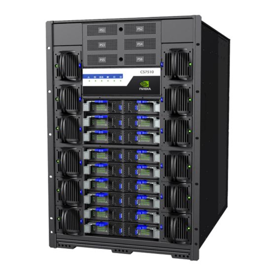
Built with Mellanox’s 6th and 7th generation of Switch-IB™ and Switch-IB™ 2 switch devices, CS7510 systems provide up to 100Gb/s full bidirectional bandwidth per port. With up to 324 ports in a 16U rack space, this system is among the densest switching systems available. -
Page 14: Management Module Mac
The switch itself is 16U tall but requires an extra 1U to install the shelf. The switch ships in a minimum base configuration plus additional modules depending on the chosen customer configuration. Optional modules included: • Management modules • Spine modules • Leaf modules Mellanox Technologies... -
Page 15: Figure 4: Cs7510
Each leaf has 36 ports and up to 9 leafs can fit in the chassis Power supplies Chassis fan modules Spines AC inlets: 6 Power supply units: 6 Management modules: 2 Spine modules: 9 Leaf modules: 9 Chassis fan modules: 12 Mellanox Technologies... -
Page 16: Features List
The minimum complement of PSUs which allows the chassis to run at full capacity is 3. The fol- lowing two redundancy options are available: • No redundancy (combined mode) • N+N configuration (grid-redundant mode) N+N redundancy only works with a supply voltage of 220V. Mellanox Technologies... -
Page 17: Fan Redundancy
When a fan unit fails, it must remain in the chassis until a replacement is available. At that point, the failed fan unit must be promptly replaced so that the chassis remains with an empty slot for as little time as possible. Mellanox Technologies... -
Page 18: Chapter 2 Installation
Read all installation instructions before connecting the equipment to the power source. 2. Bodily Injury Due to Weight Use enough people to safely lift this product. 3. Heavy Equipment This equipment is very heavy and should be moved using a mechanical lift to avoid injuries. Mellanox Technologies... - Page 19 Disconnect all power supplies to ensure a powered down state inside of the switch platform. 11. During Lightning – Electrical Hazard During periods of lightning activity, do not work on the equipment or connect or dis- connect cables. Mellanox Technologies...
- Page 20 Warning: Replace only with UL Recognized battery, certified for maximum abnormal charging current not less than 4mA There is a risk of explosion should the battery be replaced with a battery of an incorrect type. Dispose of used batteries according to the instructions. Mellanox Technologies...
- Page 21 20 A must be incorporated in the building wiring. 24. Hazardous Radiation Exposure Caution – Use of controls or adjustment or performance of procedures other than those specified herein may result in hazardous radiation exposure. Mellanox Technologies...
-
Page 22: Environmental And Safety Recommendations
Recommended ambient temperature in the System room is 20±5 Recommended humidity range is 40%±15% without condensing. It is highly recommended that the installation sites be as isolated as possible from all sources of radio transmissions and electrical interference. Mellanox Technologies... -
Page 23: Switch Components
5. 1 box containing 104 power cords (250V 16A 2m, C19 to C20, USA UL Standard) The management, spine, and leaf modules are shipped separately. To completely populate the CS7500 chassis, one requires 2 management module boxes, 18 spine module boxes, and 18 leaf module boxes. Mellanox Technologies... -
Page 24: Unpacking The Switch System
The shock stickers turn red if the crate has been mishandled or handled roughly. If one of the shock stickers is red, notify the shipper and Mellanox. Mellanox Technologies... -
Page 25: Opening The Chassis Crate
Step 1. Unscrew and remove the top cover of the crate. Step 2. Unscrew and remove the sides of the crate. Step 3. It is highly recommended to have a screw gun or electric screwdriver for this step. Mellanox Technologies... -
Page 26: Figure 6: Crate Screws
Check the parts for visible damage that may have occurred during shipping. If anything is damaged or missing, contact your customer representative immediately. Do not remove any of the blocks or the lock-down bars at this time. Mellanox Technologies... -
Page 27: Physical Installation
The vertical supports may have to be moved so that the vertical support closest to the door is a minimum of 6cm from the inside of the door. This is required so that the shelf does not hit the door. If you move the vertical supports make sure that you reinstall them vertically plumb. Mellanox Technologies... -
Page 28: Installation Kit Parts
Riveted left chassis slide Weld bracket Support bracket 10-32 hex-head screw M5 spring washer Spring washer #10 M5 pan-head screw M6X25 pan-head screw M6X16 pan-head screw Shelf arm bracket M6 cage nut Support bracket Perforated fixing bracket Flat washer #10 Mellanox Technologies... -
Page 29: Table 5: Chassis Installation Kit Items
Item No. Quantity Description Item No. M6X16 hex-head screw –––––––––––– –– –– a. Use the item number to identify the corresponding item in Figure 8. Each item number appears in a call-out bubble. Figure 8: Chassis Installation Kit Mellanox Technologies... -
Page 30: Table 6: Cable Management Installation Kit Parts
Left riveted cable holder Pan-head screw Right riveted cable holder M6 cage nut a. Use the item number to identify the corresponding item in Figure 9. Each item number appears in a call-out bubble. Figure 9: Cable Management Installation Mellanox Technologies... -
Page 31: Required Installation Tools
The shelf installation kit includes 18 shelves only. Figure 10: Shelf Installation Kit 2.5.2 Required Installation Tools Figure 11 includes the tools which are required for the installation of the director switch chassis. Figure 11: Tools for Installation Mellanox Technologies... -
Page 32: Installation Procedure
(Figure 12). It is recommended to set the shelf at U3 since the chassis would roll off more easily on it from the pallet. Figure 12: Cage Nut Placement for Shelf on BEAM-1 and BEAM-2 Mellanox Technologies... -
Page 33: Figure 13: Cage Nut Placement For Shelf On Beam-3 And Beam-4
Insert 6 M6 cage nuts from the inside each of BEAM-3 and BEAM-4 on the leaf side in Step 2. order to support the shelf (Figure 13). Figure 13: Cage Nut Placement for Shelf on BEAM-3 and BEAM-4 Mellanox Technologies... -
Page 34: Figure 14: Cage Nut Placement For Support Bracket
Place the top end of the support bracket at the top of U4 using 2 M6x25 screws and 2 M6 Step 3. flat washers on BEAM-3 and BEAM-4 (Figure 14). Do not tighten the screws completely at this point. Figure 14: Cage Nut Placement for Support Bracket Mellanox Technologies... -
Page 35: Figure 15: Cage Nut Placement For Switch System Chassis On Spine Side
Figure The indexes in Figure 15 count from the first rack hole above the shelf. Figure 15: Cage Nut Placement for Switch System Chassis on Spine Side Mellanox Technologies... -
Page 36: Figure 16: Cage Nut Placement For Cable Holders On Leaf Side
Figure The indexes in Figure 16 count from the first rack hole above the shelf. Figure 16: Cage Nut Placement for Cable Holders on Leaf Side Mellanox Technologies... -
Page 37: Figure 17: Loosening The Leaf-Side Shelf Arms
Installation Using a ratchet wrench, loosen the shelf arms’ M6 hex screws enough to allow for slight Step 6. movement (Figure 17). Figure 17: Loosening the Leaf-Side Shelf Arms Mellanox Technologies... -
Page 38: Figure 18: Adjusting The Leaf-Side Shelf Arms
Adjust the shelf’s leaf-side arms so that the distance between the leaf-side and spine-side Step 7. arms is at least 5mm longer than the distance between the rack beams (Figure 18). Figure 18: Adjusting the Leaf-Side Shelf Arms Mellanox Technologies... -
Page 39: Figure 19: Placing Shelf
Installation Place the shelf in U3 of the rack by inserting it at a tilt (Figure 19). Step 8. At least 2 people are necessary for installing the shelf. Figure 19: Placing Shelf Mellanox Technologies... -
Page 40: Figure 20: Tightening Shelf Cage Nut Screws On Spine Side
20). Figure 20: Tightening Shelf Cage Nut Screws on Spine Side Assemble the leaf-side M6X25 pan-head screws and the arm brackets at 3Nm torque Step 10. (Figure 21). Figure 21: Tightening Shelf Cage Nut Screws on Leaf Side Mellanox Technologies... -
Page 41: Figure 22: Tightening Spine-Side Shelf Arm Screws
(Figure 22). Figure 22: Tightening Spine-side Shelf Arm Screws Screw in 4 more M6X25 pan-head screws in the support brackets as fasteners from the leaf Step 12. side at 3Nm torque (Figure 23). Figure 23: Screwing Leaf-side Fasteners Mellanox Technologies... -
Page 42: Figure 24: Tightening Spine-Side Shelf Arm Screws
Installation Tighten the 10 hex head screws of the shelf’s leaf-side arms at 9Nm torque on both sides Step 13. (Figure 24). Figure 24: Tightening Spine-side Shelf Arm Screws Mellanox Technologies... -
Page 43: Figure 25: Tightening Leaf-Side Shelf Screws
Installation Tighten the 12 M6X25 pan-head screws of the shelf’s leaf-side arms at 9Nm torque now Step 14. that the shelf has been placed (Figure 25). Figure 25: Tightening Leaf-side Shelf Screws Mellanox Technologies... -
Page 44: Figure 26: Weld Bracket Assembly
Installation Assemble the bracket weld to the shelf on the spine side and tighten at 5Nm with 2 hex Step 15. screws, 2 spring washers and 2 flat washers. Figure 26: Weld Bracket Assembly Mellanox Technologies... -
Page 45: Figure 27: Placement Of Chassis In Rack - Top View
Figure 27: Placement of Chassis in Rack – Top View Put the crate on the fork lift or a mechanical lift. Step 17. From Step 16-Step 24, 3 people should participate in the installation process. Figure 28: Fork Lift Wooden Hinged exten- Mellanox Technologies... -
Page 46: Figure 29: Mechanical Lift
Using a fork or mechanical lift, position the middle of the leaf-side of the chassis in front of Step 20. the spine-side of the rack (Figure 30). Figure 30: Rack and Chassis Alignment Mellanox Technologies... -
Page 47: Figure 31: Rotated Strip And Bracket Weld
31). Step 21. Figure 31: Rotated Strip and Bracket Weld Unscrew the lock-down bar facing the rack. Step 22. Note that the chassis is on ball bearings, and with the lock-down bars removed, the chassis can roll off! Mellanox Technologies... -
Page 48: Figure 32: Sliding Chassis In Rack
Installation Slide the switch system chassis halfway into the rack (Figure 32). Step 23. Push only from the spine side so as to not injure your fingers during insertion. Figure 32: Sliding Chassis in Rack Mellanox Technologies... -
Page 49: Figure 33: Sliding In Chassis Slides
Slide the switch system chassis all the way into the rack until it stops. Step 24. Beware not to injure your fingers during insertion. Slide in the left and right chassis slides from the leaf side (Figure 33). Step 25. Figure 33: Sliding in Chassis Slides Mellanox Technologies... -
Page 50: Figure 34: Sliding Chassis Into Rack
Installation Slide the switch system chassis all the way into the rack (Figure 32). Step 26. Figure 34: Sliding Chassis into Rack Mellanox Technologies... -
Page 51: Figure 35: Screwing The Chassis To The Rack
Installation Screw the chassis to the rack on the spine side using 12 M6X16 screws where the cage nuts Step 27. have been placed at 9Nm torque. Figure 35: Screwing the Chassis to the Rack Mellanox Technologies... -
Page 52: Figure 36: Screwing The 4-Oval Washer Plates
Assemble the 2 4-oval washer plates to the left and right chassis slides on the leaf side Step 28. (Figure 36) at 3.23-3.58Nm torque using 4 M5 pan-head screws on each side (Figure 36). Figure 36: Screwing the 4-Oval Washer Plates Mellanox Technologies... -
Page 53: Figure 37: Removing The Weld Bracket
Installation Remove the M6X16 screws holding the weld bracket on the spine side using a ratchet Step 29. wrench (Figure 37). Figure 37: Removing the Weld Bracket Mellanox Technologies... -
Page 54: Figure 38: Leaf Side Fixing Bracket With Chassis
Place the perforated fixing bracket on the shelf from the leaf side and assemble it using a Step 30. ratchet wrench (with 8mm socket) and 6 10-32 hex screws, 6 #10 flat washers, and 6 #10 spring washers to the chassis at 3.23-3.58Nm torque (Figure 38). Figure 38: Leaf Side Fixing Bracket With Chassis Mellanox Technologies... -
Page 55: Figure 39: Spine Side Fixing Bracket With Chassis
Place the perforated fixing bracket on the shelf from the spine side and assemble it using 6 Step 31. 10-32 hex screws, 6 #10 spring washers, and 6 #10 flat washers to the chassis at 3.23- 3.58Nm torque (Figure 39). Figure 39: Spine Side Fixing Bracket With Chassis Mellanox Technologies... -
Page 56: Figure 40: Leaf Side Fixing Bracket With Shelf
Installation Screw the perforated fixing bracket on the leaf side to the shelf at 9Nm torque (Figure 40). Step 32. Figure 40: Leaf Side Fixing Bracket With Shelf Mellanox Technologies... -
Page 57: Figure 41: Spine Side Fixing Bracket With Shelf
Screw the fixing bracket on the spine side to the shelf using 3 M6X16 hex screws, 3 M6 Step 33. spring washers, and 3 M6 flat washers at 9Nm torque (Figure 41). Figure 41: Spine Side Fixing Bracket With Shelf Mellanox Technologies... -
Page 58: Ground Connections
Make sure to connect the ground post to a valid electrical ground. Use a grounding lug and a ground wire of sufficient capacity to safely convey a potential discharge. The grounding post is M-8 with 1.25mm pitch threads. A ground wire of AWG 6 or 4mm diameter is recommended for Mellanox Technologies... -
Page 59: Fru Insertion And Extraction (Hot-Swappable)
• Leaf modules • Spine modules • Leaf fan modules • Spine fan modules • Management modules For information on the ordering part numbers for these field replaceable units (FRUs), see Appendix G, “Replacement Parts Ordering Numbers,” on page 107. Mellanox Technologies... -
Page 60: Power Supply Units
Grasping the handle with one hand, push the black latch release while pulling the handle Step 4. outward. As the PSU unseats, the PSU status indicators will turn off. Remove the PSU. Step 5. To insert a power supply unit: Mellanox Technologies... -
Page 61: Leaf Modules
FW versions. Use only Switch-IB™ and Switch-IB™ 2 based ASICs, Do NOT use replacement parts based on different generations of chipsets. All replacement modules must be consistent with the chassis family and switch chip generation. -
Page 62: Figure 47: Intact Leaf Signal Connectors
Start with the ejector handles fully open; that is, at 45 degrees to the front panel of the leaf. Step 5. Holding the leaf by its sides, carefully set the leaf module halfway into the chassis. Step 6. Mellanox Technologies... -
Page 63: Spine Modules
Lock the ejector handles onto the module. Step 9. 2.7.3 Spine Modules Use only Switch-IB™ and Switch-IB™ 2 based ASICs, Do NOT use replacement parts based on different generations of chipsets. All replacement modules must be consistent with the chassis family and switch chip generation. -
Page 64: Figure 50: Management Module Numbering
If you need to hot swap spine #1 or spine #2: Make sure that two management modules are connected to the switch system. See Step 1. Figure Mellanox Technologies... -
Page 65: Figure 51: Releasing Spine Ejector Handles
Check for foreign objects in or mechanical damage to the chassis spine slots. Step 1. Check back signal connectors’ integrity. Look for any broken signal dividers or any devia- Step 2. tions from the pass criteria shown in Figure Mellanox Technologies... -
Page 66: Figure 52: Intact Spine Signal Connectors
Do not apply excessive force to slide in the spine module. If you feel resistance, remove the spine and double check both the chassis and spine for any damage. Catch the ejector handle hooks onto the vertical bar of the chassis and push the ejector han- Step 7. dles shut (Figure 54). Mellanox Technologies... -
Page 67: Fan Modules
6 on the right of the spines, and 6 on the left. When a fan module is not functioning the status LED on the fan will light up in amber. Airflow through the spines is independent of the airflow through the leafs. Mellanox Technologies... -
Page 68: Figure 55: Leaf Fan Locations On The Chassis
Figure 55: Leaf Fan Locations on the Chassis Extracting the Leaf Fan Module Push and hold the blue latch release. See Figure Step 1. Slowly pull out the fan module using the handle. Step 2. Figure 56: Leaf Fan Module Extraction Latch Releas Han- Mellanox Technologies... -
Page 69: Figure 57: Spine Fan Modules
Figure 57: Spine Fan Modules Han- Latc When a fan module is removed the indicator light will reset. Figure 58: Fan Status LED on the Spine Module Fan LED #1 Fan LED #2 Mellanox Technologies... -
Page 70: Management Module
If only one management module is used, the other management slot should be covered using a management blank unit. Each management module has a pair of ejectors that lock the module in place and serve as a lever for seating or extracting (see Figure 59). Mellanox Technologies... -
Page 71: Figure 59: Releasing Management Ejector Handles
Figure Figure 60: Intact Signal Connectors Check power connector’s integrity. Look for any damage on the power connector casing or Step 4. blades damage, or any deviations from the pass criterion shown in Figure Mellanox Technologies... -
Page 72: Figure 61: Intact Management Power Pins
By default the master is the top management module. For further information on the master and slave roles, MLNX-OS® see section “Subnet Manager (SM) High Availability (HA)” of the User Manual. Mellanox Technologies... -
Page 73: Infiniband Qsfp Cable Installation
Careful to not impede the airflow through the ventilation holes next to the InfiniBand ports. Use cable lengths which allow routing horizontally around to the side of the chassis before bending upward or downward in the rack. Mellanox Technologies... -
Page 74: Cable Holder Placement
After connecting the power cords, you may place the 18 cable supporters onto the cable holders (Figure 63). Figure 63: Cable Supporter Placement 2.9.1 Supported Approved Cables For a list of approved cables for this switch see the Mellanox approved cable list. http://www.mellanox.com/page/cables?mtag=cable_overview Mellanox Technologies... -
Page 75: Cable Power Classes
Make sure that the power cords are compatible with your outlets. Power cords for dif- ferent countries can be ordered from Mellanox. Make sure that the outlets and circuits are not overloaded. Spread out the load over at least two or three circuits or use a 3 phase circuit. Mellanox Technologies... -
Page 76: Chapter 3 Interfaces
• Off – when input voltage is 85V > V or V > 270V • DC OK – LED indicator • Green – when output voltage above 90%+/- 5% of 48V • Red – when output voltage fallen below 90%+/- 5% of 48V Mellanox Technologies... -
Page 77: System Ac Power Interface
The leaf Status indicator LED has the following LED assignment: Table 7 - Leaf Status LED LED Condition Description No power to the leaf Green: Solid Leaf is up and running Green: Flashing Leaf is booting or being restored to factory default Mellanox Technologies... -
Page 78: Table 8: Bad Port Led Configurations
3.1.3.3 UID LED Switch Identifier The UID LED is a debug feature that will become available to customers in the near future. For details please contact Mellanox Technologies support. 3.1.3.4 Leaf Module Port Connector LED Assignment Above the ports are two LEDs one for the upper port and one for the lower port . -
Page 79: Spine Module Led Indicators
Leaf connection status 3.1.4.1 Status LED Table 10 shows the spine status according to the LED condition. Table 10 - Spine Status LED LED Condition Description No power to the spine Green: Solid Spine is up and running Mellanox Technologies... -
Page 80: Table 11: Spine Fan Status Led
OK: No ports have received symbol errors recently Amber: Flashing Error: One or possibly more ports has just received a symbol error This LED shows symbol errors. Possible causes for this are: • bad cable • bad connection Mellanox Technologies... -
Page 81: Spine Side Panel Display Led Indicators
3.1.4.5 UID LED Switch Identifier The UID LED is a debug feature that will become available to customers in the near future. For details please contact Mellanox Technologies support. 3.1.5 Spine Side Panel Display LED Indicators The spine side panel display has LEDs that show the chassis condition. -
Page 82: Management Module Led Indicators
Management module is up and operating as master 3.1.6 Management Module LED Indicators Figure 70: Management Module Indications Master Sta- Leaf Fan PSU Sta- Status Spine Fan Status The management module LEDs display the switch system operating conditions. Mellanox Technologies... -
Page 83: Port Connector Interfaces
The ports on each leaf module are placed in two rows, 18 ports to a row. The ports are labeled as shown in Figure 71. The bottom row ports are flipped from the top row. See Figure Figure 71: Port Numbering Mellanox Technologies... -
Page 84: Air Flow
QSFP Cable Power Budget Classification All Switch-IB™ and Switch-IB™ 2 based switch systems are designed for active cables with a max power per module of 3.5W. This is power level 4 according to the QSFP Public Specifica- tion. -
Page 85: Management
If there is only one management module in the chassis all of the leafs and ports are reset by bringing them down and powering them up when the reset button is pushed. When the button is held down for Mellanox Technologies... - Page 86 Interfaces 15 seconds the management module is reset and the password is deleted. You will then be able to enter without a password and make a new password for the user “admin”. Mellanox Technologies...
-
Page 87: Chapter 4 Chassis Power Up
Spine module indicators display the status of internal links to the installed leaf modules. All Step 3. PHY links to existing leafs should be ON. Check the spine LEDs and make sure they coincide with Figure Step 4. Mellanox Technologies... -
Page 88: Switch Shut-Down Procedure
The chassis cannot be shut down using remotely. To shut it down, the power plugs need to be physically pulled from the power grid. To reboot any of the modules accessible through CLI, the command “reload” must be run on them in configuration mode “Config” as shown in the following: switch (config)# reload Mellanox Technologies... -
Page 89: Chapter 5 Switch Management Tools
Ethernet switches which must be configured to 10/100M auto-negotiation. The CS7510 switch system is pre-installed with MLNX-OS® management software. MLNX-OS is installed on all Switch-IB™ and Switch-IB™ 2 based managed switch systems. MLNX-OS includes a CLI, WebUI, SNMP, and XML interfaces which facilitate configuring chassis man- agement features, and InfiniBand management software (OpenSM). -
Page 90: Infiniband Subnet Manager
Switch Management Tools • Switch-IB™ and Switch-IB™ 2 FW version • switch temperatures The manager also has the ability to burn new firmware and upgrade software on the switch. InfiniBand Subnet Manager The InfiniBand Subnet Manager (SM) is a centralized entity running in the switch. It discovers and configures all the InfiniBand fabric devices to enable traffic flow between those devices. -
Page 91: Chapter 6 Troubleshooting
3. Make sure that the latest FW version is installed on both the HCA card and the switch. 4. If media adapters are used check that the all connections are good, tight, and secure. 5. Replace the cable. Issue 3. The activity indication does not come on Mellanox Technologies... -
Page 92: Management Module
Should any of the modules shut down due to over temperature, follow the procedure starting in Step 2 Amber LED for the spine fan on the management module is lit Issue 3. 1. Check the MLNX-OS management for confirmation and possible explanation of the alert. Mellanox Technologies... -
Page 93: Spine Module
U-Boot 2009.01-mlnx1.4 (May 12 2010 - 14:08:15) CPU: AMCC PowerPC 460EX Rev. A at 1000 MHz (PLB=200, OPB=100, EBC=100 MHz) Security/Kasumi support Bootstrap Option H - Boot ROM Location I2C (Addr 0x52) Internal PCI arbiter disabled 32 kB I-Cache 32 kB D-Cache Mellanox Technologies... -
Page 94: Troubleshooting
18 :00:03 ppc 3. U-Boot prompt Choice: 5. Select the image to boot. For more detailed instructions concerning MLNX-OS® software see the Mellanox MLNX-OS® Switch-IB™ and Switch-IB™ 2 Software WebUI User’s Manual or the Mellanox MLNX-OS® Switch-IB™ Software User Manual. Mellanox Technologies... -
Page 95: Appendix A Specification Data
Passive: 5664W Maximum Optical: 7111W (includes QSFP at 3.5W) 24,264 BTUs/hr Max Heat Output Operating: 0° to 40°C Temperature Non-operating: -40° to 70°C Operating: 10%-85% non-condensing Humidity Protocol Support InfiniBand: Auto-negotiation of 100Gb/s, 56Gb/s,40Gb/s, 20Gb/s, and 10Gb/s Speed Protocol Mellanox Technologies... -
Page 96: Emi Certification
Spine fan modules: 18 EMI Certification EMI testing on a fully populated chassis has been performed with the chassis installed in a closed two-door rack with a floor plate using the chassis installation kit supplied by Mellanox Technol- ogies. Mellanox Technologies... -
Page 97: Approved Cables
For a list of all approved cables please refer to: http://www.mellanox.com/page/cables?mtag=cable_overview EMC Certifications The list of EMC certifications per chassis model type, for different markets in the world, is located on the Mellanox Website at: http://www.mellanox.com/page/environmental_compliance > Boards/Systems > Boards/Systems Certification Matrix Mellanox Technologies... -
Page 98: Appendix B Thermal Threshold Definitions
3. Emergency – 130ºC In case the firmware fails to shut down the Switch-IB™ or Switch-IB™ 2 device upon crossing the Critical threshold, the Switch-IB™ or Switch-IB™ 2 device will auto-shutdown upon crossing the Emergency (130ºC) threshold. -
Page 99: Appendix C Calculating The Weight Of A Customized Chassis
5.045 # of leaf blanks * 1.303 # of management modules * 4.877 # of management module 1.473 blanks * Total This total is in kilograms. Multiply the total by 2.2 to get the total weight in pounds. Mellanox Technologies... -
Page 100: Appendix D Calculating The Power Of A Chassis
4. Get the total switch system power consumption system power by summing up all multiplica- tion products. Table 20 - Calculating Total Switch System Power Consumption Part Quantity Power Quantity x Power IB EDR leaf with passive cables IB EDR leaf with optical cables Spine Chassis fans Management module Total power Mellanox Technologies... -
Page 101: Appendix E Qsfp Interface
Ground Rx1p Receiver Non-Inverted Data Output Receiver Inverted Data Output Rx1n Ground Ground Rx2n Receiver Inverted Data Output 3 Rx2p Receiver Non-Inverted Data Output 3 Ground Rx4n Receiver Inverted Data Output 3 Receiver Non-Inverted Data Output 3 Rx4p Mellanox Technologies... - Page 102 +3.3 V Power supply transmitter Vcc Tx Vcc 1 +3.3 V Power Supply LPMode Low Power Mode Ground Tx3p Transmitter Non-Inverted Data Input Transmitter Inverted Data Input Tx3n Ground Tx1p Transmitter Non-Inverted Data Input Transmitter Inverted Data Input Tx1n Ground Mellanox Technologies...
-
Page 103: Figure 77: Infiniband Qsfp Connector Symbol
Figure 77: InfiniBand QSFP Connector Symbol Mellanox Technologies... -
Page 104: Figure 78: Qsfp Connector Male And Female Views
Figure 78: QSFP Connector Male and Female Views Mellanox Technologies... -
Page 105: Appendix F Mng Console Interfaces
Color Not connected I²C_SCL Not connected Bl/W I²C_SDA Br/W Not connected RS232 harness cable (DB9 to RJ45) is supplied to connect a host PC to the switch’s RJ-45 Con- sole port. Figure 79: RJ45 to DB9 Harness Pinout Mellanox Technologies... -
Page 106: Appendix G Replacement Parts Ordering Numbers
Table 23 - Replacement Parts Ordering Numbers Part Description 2.5kW AC Power Supply w/ P2C air flow MTDF-PS-A Switch-IB™ EDR InfiniBand leaf blade, 36 QSFP28 ports, RoHS R6 MSB7510-E Switch-IB™ 2 EDR InfiniBand leaf blade, 36 QSFP28 ports, RoHS MSB7560-E MCS75x0 director system, Leaf – Blank MTDF-BLK-C Switch-IB™... -
Page 107: Appendix H Safety Warnings (Multiple Languages)
45°C (113°F). Moreover, to guarantee proper , allow at least 8cm (3 inches) of clearance around the ventilation openings. 6. Stacking the Chassis The chassis should not be stacked on any other equipment. If the chassis falls, it can cause bodily injury and equipment damage. Mellanox Technologies... - Page 108 13. Equipment Disposal Disposal of this equipment should be in accordance to all national laws and regula- tions. 14. Local and National Electrical Codes This equipment should be installed in compliance with local and national electrical codes. Mellanox Technologies...
- Page 109 According to the WEEE Directive 2002/96/EC, all waste electrical and electronic equipment (EEE) should be collected separately and not disposed of with regular household waste. Dispose of this product and all of its parts in a responsible and environmentally friendly way. Mellanox Technologies...
- Page 110 ת א י ש נ מ ה א צ ו ת כ ף ו ג ת ל ב ח ד ב כ ד ו י צ ת ו ל מ ש ח ת ה ת נ כ ס Mellanox Technologies...
- Page 111 ת ע ב ת ש ו ח נ מ ד נ א ב י נ י פ נ י א י ל ב כ ל ש ק ו ת י נ ו א ר ו ב י ח Mellanox Technologies...
- Page 112 ת ו י מ ו ק מ ל מ ש ח ת ו נ ק ת ל מ ש ח ת ק פ ס א ל ב כ ה נ ק ת ה ת ו נ ק ת Mellanox Technologies...
-
Page 113: Chinese)
מ ב ש מ ת ש ה ל ן י א 21. WEEE ת נ ק ת ה י ג ב ר ו נ ב ת ו י ל מ ש ח ת ו ל ב ג מ (Chinese) Mellanox Technologies... - Page 114 Mellanox Technologies...
- Page 115 10. InfiniBand 15. UL Mellanox Technologies...
- Page 116 20. WEEE Mellanox Technologies...
-
Page 117: Avertissements De Sécurité Pour L'installation (French)
8 cm (3") autour des orifices de ventilation. 6. Châssis empilé sur d'autres équipements Le châssis ne doit pas être empilé sur d'autres équipements. S'il tombe, il peut endom- mager l'équipement ou entraîner des blessures. Mellanox Technologies... - Page 118 13. Mise au rebut de l'équipement La mise au rebut de cet équipement doit se faire conformément à toutes les lois et réglementations nationales. 14. Codes électriques locaux et nationaux Cet équipement doit être installé conformément aux codes électriques locaux et nation- aux. Mellanox Technologies...
- Page 119 Selon la Directive 2002/96/CE (DEEE), tous les déchets d'équipements électriques et électroniques (EEE) doivent être collectés séparément et ne pas être mis au rebut avec les déchets ménagers habituels. Ce produit et toutes ses pièces doivent être mis au rebut d'une manière responsable, respectant l'environnement. Mellanox Technologies...
-
Page 120: Installation Sicherheitshinweise(German)
Temperatur von 45°C (113°F) betrieben werden. Es ist ein Luft- strom von 200 LFM bei maximaler Umgebungstemperatur erforderlich. Außerdem sollten mindestens 8 cm (3 in.) Freiraum um die Belüftungsöffnungen sein, um einen einwandfreien Luftstrom zu gewährleisten. Mellanox Technologies... - Page 121 12. Geräteentsorgung Die Entsorgung dieses Geräts sollte unter Beachtung aller nationalen Gesetze Bestim- mungen erfolgen. 13. Regionale und nationale elektrische Bestimmungen Dieses Gerät sollte unter Beachtung der regionalen und nationalen elektrischen Bes- timmungen installiert werden. Mellanox Technologies...
- Page 122 Achtung: Auf Schieber/Schienen montiertes Gerät ist nicht als Regal oder Arbeitsbere- ich zu nutzen. Die Schienen sind nicht dafür bestimmt, die Einheit aus dem Gestell weg zu ziehen. Sie sind nur für die permanente Installation an einem endgültigen Stan- dort gedacht, nicht für Instandhaltung und Wartung. Mellanox Technologies...
-
Page 123: Advertencias De Seguridad De Instalación (Spanish)
¡Riesgo de descarga eléctrica! Con el módulo del ventilador quitado, se obtiene acceso a las clavijas de alimentación desde dentro de la cavidad del módulo. NO introducir herramientas ni partes del cuerpo en la cavidad del módulo del ventila- dor. Mellanox Technologies... - Page 124 Al instalar o realizar el mantenimiento de este aparato en un bastidor, es preciso adoptar precauciones especiales para garantizar que el sistema se mantenga estable. En general, en un bastidor, los equipos se deben instalar comenzando desde abajo hacia arriba. Mellanox Technologies...
- Page 125 Este dispositivo se debe instalar conforme a la versión más reciente de los códigos eléctricos nacionales del país en cuestión. En América del Norte, el equipo se debe instalar de acuerdo con las disposiciones vigentes del Código Eléctrico Nacional de los EE.UU. y del Código Eléctrico de Canadá. Mellanox Technologies...
-
Page 126: Предупреждения По Технике Безопасности При Установке (Russian)
Предупреждения по технике безопасности при установке (Rus- sian) 1. Инструкция по установке Перед подключением оборудования к источнику питания следует ознакомиться с инструкцией по установке. 2. Травмы при переносе тяжелых предметов Для поднятия этого изделия следует задействовать достаточное количество людей. Mellanox Technologies... - Page 127 воздействия. Блоки питания независимы друг от друга. Чтобы обесточить все компоненты внутри платформы коммутации, следует отсоединить все блоки питания. 9. Опасность поражения электрическим током во время грозы Во время грозы запрещается использовать оборудование и подключать или отключать кабели. Mellanox Technologies...
- Page 128 Подключение к электропитанию в Европе выполняется с помощью гармонизированного шнура питания с маркировкой <HAR>, 3-жильного, с сечением жилы не менее 1,0 мм², рассчитанного на номинальное напряжение 300 В, с ПВХ оболочкой. Шнур должен иметь литую вилку, рассчитанную на 250 В, 10 А. Mellanox Technologies...
-
Page 129: Avertismente Privind Siguranţa La Instalare (Romanian)
электронного оборудования должны собираться и утилизироваться отдельно от обычных бытовых отходов. Следует утилизировать это изделие и все его части ответственным и экологически безопасным способом. Avertismente privind siguranţa la instalare (Romanian) 1. Instrucţiuni de instalare Citiţi toate instrucţiunile de instalare înainte de a conecta Mellanox Technologies... - Page 130 îndepărtat sau nu este fixat în mod sigur. 8. Multiple mufe electrice Risc de şoc electric şi pericol electric. Toate aparatele cu alimentare de la reţea sunt independente. Deconectaţi toate sursele de alimentare cu energie pentru a asigura decuplarea în inter- iorul platformei de comutare. Mellanox Technologies...
- Page 131 Acest dispozitiv trebuie să fie instalat în conformitate cu ultima versiune a codurilor electrice naţionale ale ţării în cauză. Pentru America de Nord, echipamentul trebuie să fie instalat conform cerințelor aplicabile din Codul electric naţional al SUA şi Codul electric canadian. Mellanox Technologies...
- Page 132 În conformitate cu Directiva DEEE 2002/96/CE, toate deşeurile de echipamente elec- trice şi electronice (EEE) trebuie colectate separat şi nu trebuie eliminate împreună cu deşeurile menajere obişnuite. Eliminaţi acest produs şi toate componentele sale în mod responsabil şi ecologic. Mellanox Technologies...
-
Page 133: Sigurnosna Upozorenja Za Instaliranje (Croatian)
45°C (113°F). Osim toga, kako bi se osigu- rao odgovarajući protok zraka, omogućite najmanje 8 cm (3 inča) razmaka oko otvora ventilatora. 6. Slaganje kućišta Kućište se ne bi trebalo slagati na drugu opremu. Ako kućište padne, može izazvati tje- lesne ozljede i oštećenje opreme. Mellanox Technologies... - Page 134 Ovu bi opremu trebalo instalirati, zamjenjivati i/ili servisirati samo obučeno i kvalifici- rano osoblje. 13. Odlaganje opreme Odlaganje opreme trebalo bi se vršiti sukladno nacionalnim zakonima i propisima. 14. Lokalni i nacionalni električni kodovi Ova oprema trebala bi se instalirati u skladu s lokalnim i nacionalnim električnim kodovima. Mellanox Technologies...
- Page 135 19. Nemojte koristiti preklopnik kao policu ili radnu površinu Pozor: Oprema montirana na klizače/vodilice ne bi se trebala koristiti kao polica ili radna površina. Vodilice nisu namijenjene za povlačenje uređaja iz ormarića. Služe samo za trajnu instalaciju na konačnom položaju, a ne za servisiranje i održavanje. Mellanox Technologies...
-
Page 136: Avvertenze Di Sicurezza Per L'installazione (Italiano)
Leggere tutte le istruzioni di installazione prima di collegare l’apparecchiatura all’alimentazione. 2. Lesioni a causa del peso Usare un numero di persone sufficiente per sollevare in sicurezza questo prodotto. Apparecchiatura pesante Questa apparecchiatura è molto pesante e va spostata mediante un sollevatore meccanico, per evitare lesioni. Mellanox Technologies... - Page 137 10. Collegamento/scollegamento del cavo di rame InfiniBand I cavi di rame InfiniBand sono pesanti e non flessibili. Di conseguenza, vanno collegati o scollegati con cura dai connettori. Per avvertenze/istruzioni speciali, rivolgersi al produttore di cavi. Mellanox Technologies...
- Page 138 PVC. Il cavo deve disporre di una spina stampata di potenza nominale pari a 250 V, 10 A. 17. Corrente di dispersione elevata Avvertenza: corrente di dispersione elevata; il collegamento a terra è essenziale prima di collegare l’alimentazione. Mellanox Technologies...
- Page 139 Smaltire questo prodotto e tutte le sue parti in modo responsabile e rispettoso dell’ambiente 21. Limitazioni relative all’alimentazione per la Norvegia Questa apparecchiatura è progettata esclusivamente per il collegamento a un sistema di alimentazione TN e a un sistema di alimentazione IT. Mellanox Technologies...
-
Page 140: Montaj Güvenlik Uyarıları (Türkçe)
45 °C (113 °F). Ayrıca, düzgün hava akışı sağlamak için havalandırma deliklerinin etrafında en az 8 cm (3 inç) açıklık bırakılmalıdır. 6. Şasi İstif Şasinin diğer herhangi bir ekipmanın üzerine istiflenmemesi gerekir. Şasi düşerse, fiziksel yaralanmalara ve ekipmanda hasara neden olabilir. Mellanox Technologies... - Page 141 Ekipmanın yalnızca eğitimli ve nitelikli personel tarafından monte edilmesi, değiştirilmesi ve/veya bakımının yapılması gerekir. 13. Ekipmanın Atılması Bu ekipmanın imhasında tüm ulusal yasalara ve düzenlemelere uyulması gerekir. 14. Yerel ve Ulusal Elektrik Kodları Bu ekipmanın montajında yerel ve ulusal elektrik kodlarına uyulması gerekir. Mellanox Technologies...
- Page 142 20. WEEE Yönergesi WEEE Yönergesi 2002/96/EC uyarınca, tüm elektrikli ve elektronik ekipman atıkları (EEE) ayrı olarak toplanmalı ve evsel atıklarla birlikte çöpe atılmamalıdır. Bu ürün ve tüm parçaları çevreye dost ve sorumlu bir şekilde imha edilmelidir. Mellanox Technologies...
-
Page 143: Japan Vcci Class A Statement
21. Norveç Güç Kısıtlamaları Bu ünite, bir TN güç sistemine ve sadece Norveç'in IT güç sistemine bağlanmak içindir. H.13 Japan VCCI Class A Statement H.14 Mellanox Technologies... - Page 144 Mellanox Technologies...
- Page 145 Mellanox Technologies...
- Page 146 Mellanox Technologies...
Need help?
Do you have a question about the Switch-IB and is the answer not in the manual?
Questions and answers