Mellanox Technologies SN2100 Hardware User Manual
1u switch systems
Hide thumbs
Also See for SN2100:
- Quick installation manual (8 pages) ,
- Hardware user manual (145 pages) ,
- User manual (76 pages)

Related Manuals for Mellanox Technologies SN2100


Summary of Contents for Mellanox Technologies SN2100
- Page 1 Mellanox 1U Switch Systems Hardware User Manual Models: SN2700, SN2410 and SN2100 Rev 1.6 www.mellanox.com...
- Page 2 KIND AND SOLELY FOR THE PURPOSE OF AIDING THE CUSTOMER IN TESTING APPLICATIONS THAT USE THE PRODUCTS IN DESIGNATED SOLUTIONS. THE CUSTOMER'S MANUFACTURING TEST ENVIRONMENT HAS NOT MET THE STANDARDS SET BY MELLANOX TECHNOLOGIES TO FULLY QUALIFY THE PRODUCT(S) AND/OR THE SYSTEM USING IT. THEREFORE, MELLANOX TECHNOLOGIES CANNOT AND DOES NOT GUARANTEE OR WARRANT THAT THE PRODUCTS WILL OPERATE WITH THE HIGHEST QUALITY.
-
Page 3: Table Of Contents
2.5.3 Static Rail Kit for SN2410 ......... . 27 2.5.4 Side by Side Mounting for SN2100 Rail Kit ......31 2.6 Cable Installation . - Page 4 6.3 SN2100 Series ........
- Page 5 Fan Status Rear LED Assignments (One LED per Fan) 56 Table 18: Power Supply Unit Status Front LED Assignments for SN2700 and SN2410 57 Table 19: Power Supply Unit Status Front LED Assignments for SN2100 58 Table 20: Power Supply Unit Status Rear LED Assignments 58 Table 21:...
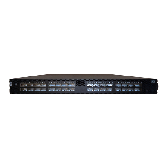
- Page 6 SN2100 Front Side View ........
- Page 7 Figure 40: SN2700 and SN2100 Cable Orientation ........
- Page 8 Updated: • “Introduction to Mellanox SN2000 Spectrum™ Ethernet Switch Systems” • “Ordering Information” • “Side by Side Mounting for SN2100 Rail Kit” May 2016 Added SX1012 to the following sections: • “Introduction to Mellanox SN2000 Spectrum™ Ethernet Switch Systems” •...
-
Page 9: About This Manual
(ONIE) Quick Start Guide Conventions The following icons are used throughout this document to indicate information that is important to the user. This icon makes recommendations to the user. This icon indicates information that is helpful to the user. Mellanox Technologies... - Page 10 Rev 1.6 This icon indicates a situation that can potentially cause damage to hardware or software. This icon indicates a situation that can potentially cause personal injury. Mellanox Technologies...
-
Page 11: Chapter 1 Introduction To Mellanox Sn2000 Spectrum™ Ethernet Switch Systems
(ONIE) for zero touch installations of network operating systems. While all Ethernet systems can be purchased preloaded with MLNX-OS, the SN2700, SN2410 and SN2100 switches (in both the 100GbE and the 40GbE versions) are offered, in addition, with Cumulus Linux support, as an alternative operating system. -
Page 12: Speed And Switching
Introduction to Mellanox SN2000 Spectrum™ Ethernet Switch Systems Figure 1: SN2700 Front Side View Figure 2: SN2410 Front Side View Figure 3: SN2100 Front Side View Figure 4: SN2700 and SN2410 Rear Side View Figure 5: SN2100 Rear Side View... -
Page 13: Management Interfaces, Psus And Fans
Introduction to Mellanox SN2000 Spectrum™ Ethernet Switch Systems Rev 1.6 Table 3 - Speed and Switching Capabilities 40/50/56/100GbE System Model 10/25GbE SFP28 Interfaces* Max Throughput QSFP28 Interfaces* SN2100 64 (using QSFP to SFP breakout 16 (or 32 50GbE 3.2Tb/s cables) interfaces when using QSFP to 2xQSFP breakout cables). -
Page 14: Ordering Information
Linux, 32 QSFP28 ports, 2 Power Supplies (AC), Standard depth, x86 CPU, P2C airflow, Rail Kit, RoHS6 MSN2700-CS2FE Spectrum™ based 100GbE 1U Development System with SDK, 32 QSFP28 ports, 2 Power Supplies (AC), Standard depth, x86 CPU, P2C airflow, Rail Kit, RoHS6 Mellanox Technologies... - Page 15 (AC), x86 dual core, Short depth, P2C airflow, Rail Kit, RoHS6 MSN2410-CB2FE Spectrum™ based 25GbE/100GbE 1U Development System with SDK, 48 SFP28 ports, 8 QSFP28 ports, 2 power supplies (AC), x86 dual core, Short depth, P2C airflow, Rail Kit, RoHS6 Mellanox Technologies...
- Page 16 Table 5 - Ordering Part Numbers (OPNs) System Description Model SN2100 MSN2100-CB2FO Spectrum™ based 100GbE 1U Open Switch with ONIE, 16 QSFP28 ports, 2 Power Supplies (AC), Short depth, Rangeley CPU, P2C air- flow, Rail Kit must be purchased separately, RoHS6 MSN2100-BB2FO Spectrum™...
-
Page 17: Safety Warnings
2. Pay attention to the air flow consideration within the system and rack - refer to “Air Flow” on page 3. Make sure that none of the package contents is missing or damaged - see “Package Contents” on page Mellanox Technologies... -
Page 18: Air Flow
7. [Optional]: FRU replacements are described in Section 2.9 on page Air Flow The following information does not apply to SN2100. In the SN2100 systems, the fan units are non-replaceable. Mellanox systems are offered with two air flow patterns: • Power (rear) side inlet to connector side outlet - marked with blue power supplies/fans- FRUs’... -
Page 19: Package Contents
• 1 – Cable retainer for each power supply unit • 1 – DB9 to RJ-45 2m harness The SN2100 package content is as follows: • 1 – System • 1 – Power cable for each power supply unit – Type C13-C14... -
Page 20: 19" Systems Mounting Options
2.5.3. For the telescopic rail kit installation instructions (can be used with SN2700 only), see Section 2.5.2. The SN2100 system is sold without a rail kit. A designated rail kit can be purchased separately. For installation instructions, see Section 2.5.4. -
Page 21: Figure 8: Rack Rail Kit Parts
2) will determine the system’s adjustable side. The system’s part to which the brackets are attached will be adjacent to the cabinet. • The FRU side is extractable. Mounting the rack brackets inverted to the FRU side (Option 2) will allow you to slide the FRUs, in and out. Mellanox Technologies... -
Page 22: Figure 9: Installation Options
Secure the system in the brack- ets by screwing the remaining 2 flat head Phillips screws (E) in the designated points with a torque of 1.5±0.2 Nm. See Figure Mellanox Technologies... -
Page 23: Figure 11: Attaching The Brackets To The Chassis
Mount the system into the rack enclosure, and attach the brackets installed on the system to the Step 5. rack’s posts. Secure the brackets to the rack’s posts by inserting four M6 screws in the desig- nated cage nuts, as described in Figure 13. Do not tighten the screws yet. Mellanox Technologies... -
Page 24: Figure 13: Attaching The Brackets To The Rack
Loosen the screws attaching the blades to the rack, and pull the blades towards you, while your Step 3. partner is holding the system. Extract the loosened screws from Step 2 and dismount the system from the rack. Step 4. Remove the rails and brackets from the chassis by unscrewing 8 screws. Step 5. Mellanox Technologies... -
Page 25: Telescopic Rail Kit For Sn2700
• 2x Phillips100 DEG F.H TYPE-I ST.ST 6-32 X 1/4 screw with around patch (F) ¹ Other threads are available by special order: M5, 10-32, 12-24 ² G-type cage-nut is available by special order. The rails must be separated prior to the installation procedure. See Figure Mellanox Technologies... -
Page 26: Figure 15: Rack Rail Kit Parts
1. Extend the rail assembly by pulling the extension outwards (D). 2. Extract rail A from rail C by pushing it outside from the rear part of the assembly. To allow com- plete separation of rail A from rail C, press the quick-release latch. Mellanox Technologies... -
Page 27: Figure 17: Installing The Cage Nuts
If cable accommodation is required, route the power cable and/or Eth cable through either of Step 3. the outer rails. Attach the switch to the left and right inner rails (A+B), by gently pushing the switch chassis’ Step 4. pins through the slider key holes, until locking occurs. Mellanox Technologies... -
Page 28: Figure 19: Attaching The Inner Rails To The Chassis
1.5±0.2 Nm. Figure 20: Securing the Chassis in the Inner Rails Slide the switch into the rack by carefully pushing the inner rails into the outer rails installed on Step 6. the rack. Mellanox Technologies... -
Page 29: Figure 21: Sliding The Switch Into The Rack
Step 2. the rack. Pull the unit out until braking is felt. For safety purposes, the locking mechanism will not allow Step 3. a complete removal of the unit at this stage. Figure 22: Pulling the Unit Outwards Mellanox Technologies... -
Page 30: Static Rail Kit For Sn2410
The following parts are included in the static rail kit (see Figure • 2x Rack mount rails (A) • 2x Rack mount blades (B) • 8x M6 Standard cage nuts¹ ² and 8x M6 Standard pan-head Phillips screws¹ (C) Mellanox Technologies... -
Page 31: Figure 24: Rack Rail Kit Parts
3.5" (8.9 cm), by optional placement of the system’s rails. • The FRU side is extractable. Mounting the rack blades inverted to the FRU side (Option 2) will allow you to slide the FRUs, in and out. Mellanox Technologies... -
Page 32: Figure 25: Installation Options
4 cage nuts in the extractable side. Note that while each rack U (unit) consists of three holes, the cage nut should be installed vertically with its ears engaging the top and bottom holes only. See Figure Mellanox Technologies... -
Page 33: Figure 27: Installing The Cage Nuts
M6 screws (D) to fix the blades into the rack. Do not tighten the screws yet. See Figure Figure 29: Sliding the Blades in the Rails Secure the system in the rack by tightening the 8 screws inserted in Step 3 and Step 4 with a Step 5. torque of 4.5±0.5 Nm. Mellanox Technologies... -
Page 34: Side By Side Mounting For Sn2100 Rail Kit
Rev 1.6 2.5.4 Side by Side Mounting for SN2100 Rail Kit A designated rail kit for the SN2100 systems can be purchased separately. This section is relevant to short-depth systems that allow such form of installation only. At least two people are required to safely mount the system in the rack. -
Page 35: Figure 30: Rack Rail Kit Parts
The following instructions apply to installation in the right part. For installation in the frame’s left part, follow the same instructions, while replacing “right” with “left”, and vice versa. Insert the SE (single ended) plugs to the dedicated inlets in the system’s rear panel. Step 1. Mellanox Technologies... -
Page 36: Figure 31: Coupling The Cables With Cable-Ties
Figure 32: Coupled Cables - Rear View Place the coupled cables in the designated area within the right flat blade (the blade with 7 Step 3. screw holes) as shown in Figure Figure 33: Cables within the Rail Mellanox Technologies... -
Page 37: Figure 34: Attach The Blades To The System
4-40 flathead screws. The recommended torque is 0.49-0.54 Nm. Figure 34: Attach the Blades to the System Figure 35: Attached Rail with Threaded Cables - Top View Slide the two frame slides into the dedicated rails in the metal frame. See Figure Step 5. Mellanox Technologies... -
Page 38: Figure 36: Sliding The Frame Sliders Into The Rails
Attach the frame to the rack by using ten spacer cage nut to adapt the square openings in the Step 7. vertical support, and screwing ten M6 pan head screws - four in the front part of the rack, and 6 in its rear part. The recommended torque is 6.55-7.35 Nm. See Figure 37. Mellanox Technologies... -
Page 39: Figure 38: Attaching The Frame To The Rack
Tighten the capture nuts to secure the system in the frame. The recommended torque on the Step 9. right screw is 3.0-3.36 Nm while on the left screw recommended torque is 0.89-0.98 Nm. Figure 39: Sliding the System’s Blades in the Rails Mellanox Technologies... -
Page 40: Cable Installation
Greater insertion force may cause damage to the cable or to the cage. The SN2410 system includes ports of different types. Figure 43 does not apply to the SFP28 ports. See Figure Figure 40: SN2700 and SN2100 Cable Orientation Mellanox Technologies... -
Page 41: Breakout Cables And Adapters
If you are using 4x10G direct attach copper cables or active optical cables, edit the /etc/cumu- to enable support for these cables, then restart the switchd service using the lus/ports.conf command. For more details, see Layer 1 and Switch sudo systemctl restart switchd Port Attributes in the Cumulus Linux User Guide. Mellanox Technologies... -
Page 42: Figure 42: Breakout Or Fanout Cables
The top QSFP28 ports marked in green are splittable to 4 SFP28 ports, each. The bottom QSFP28 ports (gray) are blocked when the upper ports are in split mode. All QSFP28 ports marked in yellow can be split to 2 SFP28 ports. Mellanox Technologies... -
Page 43: Initial Power On
The bottom QSFP28 ports - 50,52,54,56 (gray) are blocked when the upper ports are in split mode. 2.6.1.5 SN2100 Splitting Options Figure 45: SN2100 Splitting Options All QSFP28 ports are splittable. Each port can be split to 4xSFP28 (10/25G) or 2xQSFP28 (50G) ports each. There are no blocking requirements. -
Page 44: Figure 46: System Status Leds 5 Minutes After Power On In Sn2700
Figure 46: System Status LEDs 5 Minutes After Power On in SN2700 Figure 47: System Status LEDs 5 Minutes After Power On in SN 2410 Figure 48: System Status LEDs 5 Minutes After Power On in SN 2100 Mellanox Technologies... -
Page 45: System Bring-Up
Connect a host PC to the Console RJ45 ( ) port of the system, using the supplied harness Step 1. cable (DB9 to RJ45). Make sure to connect to the Console RJ45 port and not to the (Ethernet) MGT ( ) port. Mellanox Technologies... -
Page 46: Table 11: Serial Terminal Program Configuration
Step 4: Enable IPv6 auto-config This turns on auto-configuration of the IPv6 addresses. This is (SLAAC) on mgmt0 interface? unsuitable for DHCPv6. [no] Step 5: Enable DHCPv6 on To enable DHCPv6 on the MGMT0 interface. mgmt0 interface? [no] Mellanox Technologies... -
Page 47: Table 13: Configuration Wizard Session - Static Ip Configuration
To change an answer, enter the step number to return to. Otherwise hit <enter> to save changes and exit. Choice: Configuration changes saved. To return to the wizard from the CLI, enter the “configuration jump-start” command from configure mode. Launching CLI... > Mellanox Technologies... - Page 48 Check the software version embedded in your system, using the command ‘show version’. Step 6. Compare this version to the latest version that can be retrieved from Mellanox support site. To upgrade software, please refer to the MLNX-OS User Manual. Mellanox Technologies...
-
Page 49: Configuring Network Attributes Using Cumulus Linux
2.8.2.1 Remote Connection with Cumulus Linux Cumulus Linux uses the OpenSSH package to provide SSH functionality. To securely access a Cumulus Linux switch remotely, please follow the instructions on the SSH for Remote Access page in the Cumulus Linux User Guide. Mellanox Technologies... -
Page 50: Fru Replacements
Installation Rev 1.6 FRU Replacements The following information does not apply to the SN2100 series. The SN2100 systems include two non-replaceable power supply units and four non-replaceable fan units. 2.9.1 Power Supply Mellanox systems that are equipped with two replaceable power supply units work in a redun- dant configuration. -
Page 51: Fans
Make sure that the fans have the air flow that matches the model number. An air flow opposite to the system design will cause the system to operate at a higher (less than optimal) temperature. For power supply unit air flow direction, refer to Section 2.3 on page To remove a fan unit: Mellanox Technologies... -
Page 52: Figure 51: Fan Module Latches
The green Fan Status LED should light. If not, extract the fan unit and reinsert it. After system two unsuccessful attempts to install the fan unit, power off the before attempt- ing any system debug. Figure 51: Fan Module Latches Mellanox Technologies... -
Page 53: Chapter 3 Interfaces
Supported Interfaces The systems support the following interfaces: • Data interfaces - Ethernet • 10/100/1000 MbE speed rates • USB port (mini USB in SN2100) • RS232 Console port • RJ45 management interface(s) • Reset button • Status and Port LEDs In order to review the full configuration options matrix, refer to Table 4, “Management Inter-... -
Page 54: Usb
The reset button is located on the rear side of the system next to the fan status LEDs in SN2700 and SN2410, and on the front side in SN2100. This reset button requires a tool to be pressed. Do not use a sharp pointed object such as a needle or a push pin for pressing the reset button. -
Page 55: Status And Port Leds
Lights up when a symbol error is detected on one of the ports. Unit Identifier LED Lights up on command through the CLI. Off or blue when identifying a port a. There are two PSU LEDs in SN2100. Mellanox Technologies... -
Page 56: Figure 52: System Status Leds - Front And Rear Sides In Sn2700
Figure 54: System Status LED in SN2100 The LED in the read oval is located on the front panel of SN2100. There are no LEDs in the rear panel of SN2100. Both of the System Status LEDs (front and back, if exist) supply identical information. -
Page 57: Figure 55: Fan Status Led In Sn2700 - Front And Rear Sides
Figure 55: Fan Status LED in SN2700 - Front and Rear Sides Both of these LEDs in the red ovals show the fans’ status. Figure 56: Fan Status LED in SN2410 - Front and Rear Sides Both of these LEDs in the red ovals show the fans’ status. Mellanox Technologies... -
Page 58: Figure 57: Fan Status Led In Sn2100
Rev 1.6 Interfaces Figure 57: Fan Status LED in SN2100 The SN2100 systems have a front fan LED only. Table 16 - Fan Status Front LED Assignments Description Action Required Behavior Solid Green All fans are up and running. Solid Red Error, one or more fans are not operating prop- The faulty FRUs should be replaced. -
Page 59: Figure 58: Power Status Led
Rev 1.6 3.2.1.3 Power Supply Status LEDs The following information does not apply to the SN2100 systems. In these systems, the power supply units are non-replaceable, and there is a designated LED for each unit in the system’s front panel. See... -
Page 60: Bad Port Led
Rev 1.6 Interfaces Table 19 - Power Supply Unit Status Front LED Assignments for SN2100 LED Behavior Description Action Required Solid Green Power supply is running normally. Solid Red PSU is faulty or disconnected Make sure the AC cable is plugged in and active. - Page 61 Error, one or more ports have received symbol Check symbol error counters on the sys- errors. tem UI to identify the ports. Possible causes are: Replace the cable on these ports. • Bad cable • Bad connection • Bad connector Mellanox Technologies...
-
Page 62: Figure 60: Sn2700 Port Leds
Figure 61: SN2410 SFP28 Port LEDs Figure 62: SN2410 QSFP28 Port LEDs Figure 63: SN2100 Port LEDs In the SN2410 systems, the status of each pair of adjacent QSFP28 ports is indicated by four LEDs, as shown in the picture above: •... -
Page 63: Inventory Information
In some systems, there is no pull-out tab, and the information is provided on labels in sev- eral locations. Figure 64: SN2700 Pull-out Tab Mellanox Technologies... -
Page 64: Figure 65: Sn2410 Inventory Information Illustration
Rev 1.6 Interfaces Figure 65: SN2410 Inventory Information Illustration Figure 66: SN2100 Pull-out Tab Mellanox Technologies... -
Page 65: Chapter 4 Software Management
The systems do not require firmware updating. Firmware updating is done through the MLNX- OS management software. . 4.1.3 Cumulus Linux Software Upgrade For Cumulus Linux software upgrade instructions, see Upgrading Cumulus Linux in the Cumu- lus Linux User Guide. Mellanox Technologies... -
Page 66: Chapter 5 Troubleshooting
Replace the FAN FRU if needed (possible in SN2700 and SN2410 only) PSU Status LED is red Cause: Possible PSU issue Solution:. • Check/replace the power cable • Replace the PSU if needed (possible in SN2700 and SN2410 only) Mellanox Technologies... - Page 67 • Select previous image to boot by pressing an arrow key and choosing the appropriate image. System boot failure Software upgrade failed Monitoring and Troubleshooting Cumulus Linux while using Cumu- on x86 based systems User Guide. lus Linux Mellanox Technologies...
-
Page 68: Chapter 6 Specifications
Typical power with passive cables (ATIS): 150W Max power with optical cables (assuming 3.5W per port): 398W Main Devices CPU: Intel x86 1.40GHZ Dual Core PCIe: 4x Gen2.0 Switch: Mellanox Spectrum™ Memory: 8GB DDR3 RAM, 32GB SSD Switching Capacity: 3.2Tb/s Mellanox Technologies... -
Page 69: Sn2410 Series
Max power with optical cables (assuming 3.5W per each QSFP28 port, and 1.5W per each SFP28 port): 362W Main Devices CPU: Intel x86 1.40GHZ Dual Core PCIe: 4x Gen2.0 Switch: Mellanox Spectrum™ Memory: 8GB DDR3 RAM 32GB SSD Switching Capacity: 2Tb/s Mellanox Technologies... -
Page 70: Sn2100 Series
Specifications Rev 1.6 SN2100 Series Table 26 - SN2100 Specifications Feature Value Mechanical Size: 43.8mm (H) x 200mm (W) x 508mm (D) 1.72" (H) x 7.87" (W) x 20" (D) Mounting: 19" Rack mount Weight: 4.540kg Speed: 10/25/40/50/56/100GbE per port... - Page 71 Rack installation kit for 1U wide systems to be mounted into standard depth racks MTEF-KIT-D Rack installation kit for SN2100 series short depth 1U switches, allows instal- lation of one or two switches side-by-side into standard depth racks MTEF-PSF-AC-A 460W AC Power Supply w/ rear to front air flow...
- Page 72 • Emergency – 130°C: In case the firmware fails to shut down the device upon crossing the Critical threshold, the device will auto-shutdown upon crossing the Emergency (130°C) threshold. For thermal threshold definitions in Cumulus Linux, see Configuring Net-SNMP Event Notification Traps in the Cumulus Networks Help Center. Mellanox Technologies...
- Page 73 Vcc Tx +3.3 V Power supply transmitter Vcc 1 +3.3 V Power Supply LPMode Low Power Mode Ground Tx3p Transmitter Non-Inverted Data Input Tx3n Transmitter Inverted Data Input Ground Tx1p Transmitter Non-Inverted Data Input Tx1n Transmitter Inverted Data Input Mellanox Technologies...
-
Page 74: Figure 67: Qsfp28 Connector Male And Female Views
Rev 1.6 Figure 67: QSFP28 Connector Male and Female Views 18.35 View into Rear of Connector 8.50 18.35 View into Front of Cage 8.50 Mellanox Technologies... -
Page 75: Figure 68: Rear View Of Module With Pin Placement
Rev 1.6 SFP28 Interface 56.50 13.90 Mellanox Technologies 11.85 13.60 14.80 13.70 MTSFPP-SR Module 1.55 0.50 8.50 0.60 2.55 1.80 44.95 Figure 68: Rear View of Module With Pin Placement 13.70 8.50 Mellanox Technologies... - Page 76 MOD_ABS pulls line low to indicate module is plugged in. e. LOS is open collector output. Should be pulled up with 4.7kΩ – 10kΩ on host board to a volt- age between 2.0V and 3.6V. Logic 0 indicates normal operation; logic 1 indicates loss of sig- nal. Mellanox Technologies...
-
Page 77: Figure 69: Rj45 To Db9 Harness Pinout
Rev 1.6 RJ45 to DB9 Harness Pinout In order to connect a host PC to the Console RJ45 port of the system, a RS232 harness cable (DB9 to RJ45) is supplied. Figure 69: RJ45 to DB9 Harness Pinout Mellanox Technologies... - Page 78 (EEE) should be collected separately and not disposed of with regular household waste. Dispose of this product and all of its parts in a responsible and environmentally friendly way. Follow the instructions found at http://www.mellanox.com/page/dismantling_procedures proper disassembly and disposal of the switch, according to the WEEE directive. Mellanox Technologies...
- Page 79 5. Over-temperature This equipment should not be operated in an area with an ambient temperature exceed- ing the maximum recommended: 45°C (113°F). Moreover, to guarantee proper , allow at least 8cm (3 inches) of clearance around the ventilation openings. Mellanox Technologies...
- Page 80 When this product is mounted or serviced in a rack, special precautions must be taken to ensure that the system remains stable. In general you should fill the rack with equip- ment starting from the bottom to the top. Mellanox Technologies...
- Page 81 This device must be installed according to the latest version of the country national electrical codes. For North America, equipment must be installed in accordance to the applicable requirements in the US National Electrical Code and the Canadian Electri- cal Code. Mellanox Technologies...
- Page 82 24. Country of Norway Power Restrictions This unit is intended for connection to a TN power system and an IT power system of Norway only. Hebrew ) אזהרות בטיחות בהתקנה הוראות התקנה .קרא היטב את כל הוראות ההתקנה לפני חיבור המוצר לחשמל Mellanox Technologies...
- Page 83 (. בנוסף, כדי להבטיח כניסת אוויר תקינה, יש לוודא כי קיים שטח 45°C (113°F :המומלצת .אינץ’( לפחות סביב פתחי האוורור ) ס”מ פנוי של ערימת המערכת .אין לערום את המערכת על גבי ציוד אחר. במקרה של נפילה, עשויים להגרם נזקי גוף ורכוש Mellanox Technologies...
- Page 84 להבטיח שיוותר יציב. ככלל, יש להתחיל למלא את הארון מהמדף התחתון, ולהתקדם .כלפי מעלה התקנת המוצר כל התקנה, החלפה או טיפול במוצר זה חייבות להתבצע על ידי איש צוות מיומן .ומוסמך בלבד השלכה לאשפה בתום השימוש השלכת המוצר בתום השימוש חייבת להיעשות בהתאם לכל התקנות והחוקים .המקומיים Mellanox Technologies...
- Page 85 יש להקפיד על המצאותם בבניין ועל זמינותם של אמצעים להגנה מפני מתח גבוה בתקן אין להשתמש במערכת כמדף או כשטח עבודה זהירות: אין להשתמש בציוד כמדף או כשטח עבודה. המסילות לא נועדו לשליפת המערכת .מהארון, אלא להתקנת המערכת במיקומה הקבוע והסופי בארון Mellanox Technologies...
- Page 86 אספקת חשמל מסוג 安裝安全性警告 (Chinese) 1. 安裝指示 本設備附有備援電源供應器或在適當位置配有空白蓋板。 2. 因重量導致的人身受傷 為了安全起見,請安排足夠的人員以合力抬起本產品。 <40 lbs 70 - 121 lbs >121 lbs 40 - 70 lbs <18 kgs 32 - 55 kgs >55 kgs 18 - 32 kgs 3. 重設備 本設備極重,應使用機械式起重機來搬移,以避免人員受傷。 Mellanox Technologies...
- Page 87 請勿將工具或機身零件插入到風扇模組空腔內。 5. 溫度過高 本設備不應在超過所建議的最高環境溫度的區域中運作:45°C (113°F)。此外, 為了保證氣流的流通正常,請在通風口旁保留至少 8 公分 (3 英吋 ) 的間距。 6. 堆疊機箱 機箱不應堆疊在任何其他設備上。如果機箱掉落,可能造成人員受傷與設備損 壞。 7. 複式電源連接時的電擊危險 本設備附有備援電源供應器或在適當位置配有空白蓋板。如果是電源供應器空 白蓋板,在空白蓋板已取下或未牢牢固訂的情況下,請勿操作本產品。 8. 雙極 / 中性保險絲 本系統具有雙極 / 中性保險絲。請拔掉所有電源線後,再打開本產品的蓋板或 碰觸任何內部零件。 9. 多電源輸入座 電擊與能源危害的危險。 所有 PSU 均各自獨立。 將所有電源供應器斷電,確保交換器平台內部在電源關閉狀態。 10. 閃電時的電擊危險 在閃電期間,不要使用本設備或連接或拔下纜線。 Mellanox Technologies...
- Page 88 17. UL 列名和 CSA 認證電源線 北美地區在接上電源時,請選用獲得 UL 列名和 CSA 認證、三個導體、[16 AWG] 附成型插頭,額定值為 125 V、[13 A],長度至少 1.5 公尺 [ 六英尺 ],但 不超過 4.5 公尺的電源線。 歐洲地區在接上電源時,請選用國際協調式且標示有 <HAR> 字樣、三個導體、 標稱截面至少 1.0 平方公厘,額定值為 300 V,採用 PVC 絕緣的電源線。電源 線需有成型插頭,額定值為 250 V, 10 A。 Mellanox Technologies...
- Page 89 連接至 RS232 設備和乙太網路介面的纜線必須是 UL 認證類型 DP-1 或 DP-2。 ( 請注意位於非 LPS 電路時 ) 過電流保護:準備好使用的列名分支電路過電流保護裝置最大額定值 20 A 必須 整合在配線中。 21. 切換開關不可用作機架或工作空間 小心:滑軌 / 導軌安裝設備不可用作機架或工作空間。導軌不適用於將設備滑 出機架使用。僅限永久安裝在最後安置區域時使用,不可用於維修和保養。 22. WEEE 指令 根據 WEEE 指令 2002/96/EC,所有廢棄的電氣與電子設備 (EEE),應分開集 中,而且不應與一般家庭廢棄物一起棄置。 請以負責和環保的方式棄置本產品及其所有零件。 23. 挪威國家電源限制 本設備僅限連接至挪威的 TN 電源系統和 IT 電源系統。 Mellanox Technologies...
- Page 90 24. China CCC Warning Statement 25. Taiwan BSMI Class A Statement - Warning to the User! Mellanox Technologies...
- Page 91 8 cm (3") autour des orifices de ventilation. 6. Châssis empilé sur d'autres équipements Le châssis ne doit pas être empilé sur d'autres équipements. S'il tombe, il peut endom- mager l'équipement ou entraîner des blessures. Mellanox Technologies...
- Page 92 En règle générale, le rack doit être rempli en commençant par le bas. 13. Installation de l'équipement Cet équipement ne doit être installé, remplacé et maintenu que par un personnel formé et qualifié. Mellanox Technologies...
- Page 93 Cet appareil doit être installé conformément à la version la plus récente des codes élec- trique nationaux. En Amérique du Nord, l'équipement doit être installé en respectant les exigences de l'US National Electrical Code et du Code canadien de l'électricité. Mellanox Technologies...
- Page 94 24. Restrictions concernant l'alimentation pour la Norvège Cet appareil est prévu pour être relié à un système d'alimentation TN et un système d'alimentation informatique de Norvège uniquement. Installation Sicherheitshinweise(German) 1. Installationsanleitungen Lesen Sie alle Installationsanleitungen, bevor Sie das Gerät an die Stromversorgung anschließen. Mellanox Technologies...
- Page 95 Verletzungen und Beschädigungen an Geräten führen. 7. Zweipolig/Neutrale Sicherung Achtung: Zweipolige bzw. Neutralleiter-Sicherung im Netzteil. Netzstecker ziehen, um sicher- zustellen, daß keine Spannung am Gerät anliegt. Entfernen Sie alle Netzkabel vor dem Öffnen der Abdeckung dieses Produkts oder dem Berühren der Innenteile. Mellanox Technologies...
- Page 96 13. Geräteentsorgung Die Entsorgung dieses Geräts sollte unter Beachtung aller nationalen Gesetze Bestim- mungen erfolgen. 14. Regionale und nationale elektrische Bestimmungen Dieses Gerät sollte unter Beachtung der regionalen und nationalen elektrischen Bes- timmungen installiert werden. Mellanox Technologies...
- Page 97 Kabel für den Anschluss an das Gerät RS232-und Ethernet-Schnittstellen müssen UL zertifiziert Typ DP-1 oder DP-2. (Hinweis-, wenn nicht mit Wohnsitz in LPS-Schal- tung) Überstromschutz: Eine leicht zugängliche Auflistung Abzweigleitung Überstrom- Schutzeinrichtung 20 A bewertet werden müssen in dem Gebäude Verkabelung. Mellanox Technologies...
- Page 98 >121 lbs 40 - 70 lbs <18 kgs 32 - 55 kgs >55 kgs 18 - 32 kgs 3. Equipos pesados Dado que el equipo es pesado, se debe mover únicamente mediante un elevador mecánico, para evitar lesiones. Mellanox Technologies...
- Page 99 Desconecte todas las fuentes de alimentación, para asegurar que no haya corriente alguna dentro de la plataforma de conmutación. 10. Al haber rayos: peligro de descarga No utilizar el equipo ni conectar o desconectar cables durante períodos de actividad de rayos. Mellanox Technologies...
- Page 100 II y a danger d’explosion s’il y a remplacement incorrect de la batterie. Remplacer uniquement avec une batterie du même type ou d’un type équivalent recommandé par le constructeur. Mettre au rebut les batteries usagées conformément aux instructions du fabricant. Mellanox Technologies...
- Page 101 (EEE) se deben recolectar por separado y no se deben eliminar junto con residuos domésticos. Al deshacerse de este producto y de todas sus partes, hágalo de una manera respons- able y respetuosa con el medio ambiente. Mellanox Technologies...
- Page 102 Более того, для надлежащей вентиляции следует обеспечить зазор вокруг вентиляционных отверстий не менее 8 см (3 дюйма). 6. Установка шасси поверх другого оборудования Не устанавливать шасси поверх другого оборудования. Падение шасси может привести к травмам и повреждению оборудования. Mellanox Technologies...
- Page 103 12. Установка или обслуживание в стойке При установке или обслуживании этого изделия в стойке следует обеспечить устойчивость системы. Как правило, стойка заполняется оборудованием снизу вверх. 13. Установка оборудования Устанавливать, заменять и/или обслуживать это оборудование должен только подготовленный и квалифицированный персонал. Mellanox Technologies...
- Page 104 сечением жилы не менее 1,0 мм², рассчитанного на номинальное напряжение 300 В, с ПВХ оболочкой. Шнур должен иметь литую вилку, рассчитанную на 250 В, 10 А. 19. Высокий ток утечки Осторожно! Высокий ток утечки. Заземлить перед подключением к электропитанию. Mellanox Technologies...
- Page 105 электронного оборудования должны собираться и утилизироваться отдельно от обычных бытовых отходов. Следует утилизировать это изделие и все его части ответственным и экологически безопасным способом. Avertismente privind siguranţa la instalare (Romanian) 1. Instrucţiuni de instalare Citiţi toate instrucţiunile de instalare înainte de a conecta. Mellanox Technologies...
- Page 106 Acest produs include o sursă de alimentare suplimentară sau un spaţiu gol în locul acesteia. În cazul în care spaţiul pentru sursa de alimentare este gol, nu operaţi produ- sul când capacul orb este îndepărtat sau nu este fixat în mod sigur. Mellanox Technologies...
- Page 107 începând de jos în sus. 13. Instalarea echipamentului Acest echipament trebuie să fie instalat, înlocuit şi/sau depanat numai de către personal instruit şi calificat. 14. Eliminarea echipamentului Eliminarea acestui echipament trebuie să se realizeze în conformitate cu toate legile şi regulamentele naţionale. Mellanox Technologies...
- Page 108 Acest dispozitiv trebuie să fie instalat în conformitate cu ultima versiune a codurilor electrice naţionale ale ţării în cauză. Pentru America de Nord, echipamentul trebuie să fie instalat conform cerințelor aplicabile din Codul electric naţional al SUA şi Codul electric canadian. Mellanox Technologies...
- Page 109 This unit is intended for connection to a TN power system and an IT power system of Norway only. E.10 Sigurnosna upozorenja za instaliranje (Croatian) 1. Upute za instaliranje Pažljivo pročitajte upute za instaliranje prije spajanja opreme na izvor električne energije. Mellanox Technologies...
- Page 110 7. Redundantno napajanje - Opasnost od električne energije Ovaj proizvod uključuje redundantno napajanje ili prazan prostor na njegovu mjestu. U slučaju praznog prostora za napajanje, nemojte rukovati proizvodom ako je pok- lopac uklonjen ili ako nije dobro pričvršćen. Mellanox Technologies...
- Page 111 13. Instaliranje opreme Ovu bi opremu trebalo instalirati, zamjenjivati i/ili servisirati samo obučeno i kvalifici- rano osoblje. 14. Odlaganje opreme Odlaganje opreme trebalo bi se vršiti sukladno nacionalnim zakonima i propisima. Mellanox Technologies...
- Page 112 DP-1 ili DP-2. (Napomena - kad se nalazi u krugu bez LPS vodiča) Zaštita od strujnog preopterećenja: Uvijek dostupni odobreni zaštitni uređaji od stru- jnog preopterećenja nazivne struje od 20 A moraju se ugraditi u ožičenje zgrade. Mellanox Technologies...
- Page 113 2. Lesioni a causa del peso Usare un numero di persone sufficiente per sollevare in sicurezza questo prodotto. <40 lbs 70 - 121 lbs >121 lbs 40 - 70 lbs <18 kgs 32 - 55 kgs >55 kgs 18 - 32 kgs Mellanox Technologies...
- Page 114 9. Prese di alimentazione multiple Rischio e pericolo di scosse elettriche. Gli alimentatori sono tutti indipendenti. Scollegare tutti gli alimentatori per assicurarsi che il commutatore non sia sotto tensione Mellanox Technologies...
- Page 115 Questo dispositivo va installato in conformità con l’ultima versione dei codici elettrici nazionali del Paese. Per il Nord America, l’apparecchiatura va installata in conformità con i requisiti applicabili del “codice elettrico nazionale USA” e del “codice elettrico canadese”. Mellanox Technologies...
- Page 116 Attenzione: un’apparecchiatura scorrevole o montata su binari non va utilizzata come scaffale o piano di lavoro. I binari non sono progettati per far scorrere e allontanare l’unità dal rack. Essi sono destinati all’installazione permanente solo nel luogo di lavoro e non vengono utilizzati per assistenza e manutenzione Mellanox Technologies...
- Page 117 Bu ekipman çok ağırdır ve yaralanmaları önlemek için ekipmanın mekanik asansör kullanılarak taşınması gerekir. 4. Elektrik Çarpması Riski! Bu ekipman, önerilen maksimum ortam sıcaklığını aşan alanlarda çalıştırılmamalıdır: 45 °C (113 °F). Ayrıca, düzgün hava akışı sağlamak için havalandırma deliklerinin etrafında en az 8 cm (3 inç) açıklık bırakılmalıdır. Mellanox Technologies...
- Page 118 Gökyüzünde şimşek çaktığı zamanlarda, ekipman üzerinde çalışmayın veya kablo bağlamayın ya da kablo bağlantısı kesmeyin. 11. İskele Montajı ve Bakım Bu ürün bir iskelede monte edildiyse veya bir iskele ile sunulduysa, sistemin sabit kalması için özel önlemler alınmalıdır. Genelde, ekipmanları iskeleye aşağıdan yukarı doğru doldurmanız gerekir. Mellanox Technologies...
- Page 119 300 V değerinde ve PVC yalıtımlı bir güç kaynağı kablosu seçin. Kablonun 250 V, 10 A değerinde bir kalıplanmış fişi olması gerekmektedir. 18. Yüksek Kaçak Akım Yüksek kaçak akım varsa; güç kaynağına bağlanmadan önce mutlaka topraklama bağlantısı yapılmalıdır. Mellanox Technologies...
- Page 120 (EEE) ayrı olarak toplanmalı ve evsel atıklarla birlikte çöpe atılmamalıdır. Bu ürün ve tüm parçaları çevreye dost ve sorumlu bir şekilde imha edilmelidir. 23. Norveç Güç Kısıtlamaları Bu ünite, bir TN güç sistemine ve sadece Norveç'in IT güç sistemine bağlanmak içindir. E.13 Japan VCCI Statement Mellanox Technologies...
Need help?
Do you have a question about the SN2100 and is the answer not in the manual?
Questions and answers