Mellanox Technologies Spectrum SN2700 Hardware User Manual
1u switch systems
Hide thumbs
Also See for Spectrum SN2700:
- Hardware user manual (109 pages) ,
- User manual (76 pages) ,
- Quick installation manual (8 pages)

Related Manuals for Mellanox Technologies Spectrum SN2700


Summary of Contents for Mellanox Technologies Spectrum SN2700
- Page 1 Mellanox Spectrum™ 1U Switch Systems Hardware User Manual Models: SN2700, SN2740, SN2410 and SN2100 Rev 1.9 www.mellanox.com Mellanox Technologies...
- Page 2 NOTE: THIS HARDWARE, SOFTWARE OR TEST SUITE PRODUCT (“PRODUCT (S)”) AND ITS RELATED DOCUMENTATION ARE PROVIDED BY MELLANOX TECHNOLOGIES “AS -IS” WITH ALL FAULTS OF ANY KIND AND SOLELY FOR THE PURPOSE OF AIDING THE CUSTOMER IN TESTING APPLICATIONS THAT USE THE PRODUCTS IN DESIGNATED SOLUTIONS.
-
Page 3: Table Of Contents
3.2 LEDs ............62 Rev 1.9 Mellanox Technologies... - Page 4 6.4 SN2100 Series ..........80 Mellanox Technologies...
- Page 5 Table 31: QSFP Interface Pins 24-38 ..........84 Rev 1.9 Mellanox Technologies...
- Page 6 Figure 35: Cables within the Rail ............42 Mellanox Technologies...
- Page 7 Figure 71: SN2410 QSFP28 Port LEDs ..........70 Rev 1.9 Mellanox Technologies...
- Page 8 Figure 78: RJ45 to DB9 Harness Pinout ..........87 Mellanox Technologies...
-
Page 9: Table 1: Revision History Table
“Introduction to Mellanox SN2000 Spectrum™ Ethernet Switch Sys- tems” • “Software Management” • “Troubleshooting Instructions” • “Specifications” • “Accessory and Replacement Parts” Added: • Taiwan BSMI Class A Statement in Safety Warnings December 2015 Added SN2410 August 2015 Initial revision Rev 1.9 Mellanox Technologies... -
Page 10: Table 2: References
Quick Start Guide Conventions The following icons are used throughout this document to indicate information that is important to the user. This icon makes recommendations to the user. This icon indicates information that is helpful to the user. Mellanox Technologies Rev 1.9... - Page 11 This icon indicates a situation that can potentially cause damage to hardware or software. This icon indicates a situation that can potentially cause personal injury. This icon indicates a situation that can potentially cause personal injury. Rev 1.9 Mellanox Technologies...
-
Page 12: Chapter 1 Introduction To Mellanox Sn2000 Spectrum™ Ethernet Switch Systems
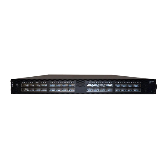
MLNX-OS, the SN2000 switches (in both the 100GbE and the 40GbE versions) are offered, in addition, with Cumulus Linux support, as an alternative operat- ing system. For a full list of all available ordering options, see “Ordering Information”. Figure 1: SN2700 Front Side View Mellanox Technologies Rev 1.9... -
Page 13: Figure 2: Sn2740 Front Side View
Figure 2: SN2740 Front Side View Figure 3: SN2410 Front Side View Figure 4: SN2100 Front Side View Figure 5: SN2700 and SN2410 Rear Side View Figure 6: SN2740 Rear Side View Figure 7: SN2100 Rear Side View Rev 1.9 Mellanox Technologies... -
Page 14: Speed And Switching
In the main menu, click on Products--> Ethernet Switch Systems, and select the desired product page. Certifications The list of certifications (such as EMC, Safety and others) per system for different regions of the world is located on the Mellanox website at: http://www.mellanox.com/page/environmental_compliance Mellanox Technologies Rev 1.9... -
Page 15: Ordering Information
Spectrum(TM) 100GbE 1U switch w/Cumulus Linux, 32 QSFP28 ports, 2 AC PSUs, x86 2core, standard depth, C2P airflow, Rail Kit, RoHS6, (Cumulus License Key is required, provided at no cost with purchase of support SKU SUP-SN2000-XX) Rev 1.9 Mellanox Technologies... - Page 16 QSFP28 ports, 2 Power Supplies (AC), Short depth, x86 CPU, P2C airflow, Rail Kit, RoHS6 MSN2740- Spectrum(TM) based 100GbE 1U Open Switch with ONIE/SONIC, CB2F1OS 32 QSFP28 ports, 2 Power Supplies (AC), Short depth, x86 CPU, P2C airflow, Rail Kit, RoHS6 Mellanox Technologies Rev 1.9...
- Page 17 Rail Kit, (Cumulus License Key is required) MSN2410-CB2RO Spectrum(TM) based 25GbE/100GbE 1U Open Ethernet switch with ONIE, 48 SFP28 ports, 8 QSFP28 ports, 2 power supplies (AC), x86 dual core, Short depth, C2P airflow, Rail Kit, RoHS6 Rev 1.9 Mellanox Technologies...
- Page 18 C2P airflow, Rail Kit must be purchased separately, RoHS6 MSN2100-CB2RC Spectrum(TM) 100GbE 1U switch w/Cumulus Linux, 16 QSFP28 ports,2 AC PSUs,x86 2core, short depth, C2P airflow, Rails 2 be pur- chased separately, (Cumulus License Key is required) Mellanox Technologies Rev 1.9...
-
Page 19: Chapter 2 Installation
119. • For Safety Warnings in Italian, see Section E.11, “Avvertenze di sicurezza per l’installazione (Italian),” on page 123. • For Safety Warnings in Turkish see Section E.12, “Montaj Güvenlik Uyarıları (Turk- ish),” on page 127. Rev 1.9 Mellanox Technologies... -
Page 20: System Installation And Initialization
All servers and systems in the same rack should be planned with the same airflow direction. All FRU components need to have the same air flow direction. A mismatch in the air flow will affect the heat dissipation. Mellanox Technologies Rev 1.9... -
Page 21: Package Contents
Before installing your new system, unpack it and check against the parts list below that all the parts have been sent. Check the parts for visible damage that may have occurred during shipping. The SN2700, SN2740 and SN2410 package content is as follows: • 1 – System • 1 – Rail kit Rev 1.9 Mellanox Technologies... -
Page 22: 19" Systems Mounting Options
Short (17”-24”) or Standard (24”-34”) The following parts are included in the static rail kit (see Figure 10): • 2x Rack mount rails (A) • 2x Rack mount brackets (B) • 2x Rack mount blades (C) Mellanox Technologies Rev 1.9... -
Page 23: Figure 10: Rack Rail Kit Parts
2) will determine the system’s adjustable side. The system’s part to which the brackets are attached will be adjacent to the cabinet. • The FRU side is extractable. Mounting the rack brackets inverted to the FRU side (Option 2) will allow you to slide the FRUs, in and out. Rev 1.9 Mellanox Technologies... -
Page 24: Figure 11: Installation Options
Secure the chassis in the rails by screwing 2 flat head Phillips screws (E) in the designated Step 2. points with a torque of 1.5±0.2 Nm. See Figure Mellanox Technologies Rev 1.9... -
Page 25: Figure 12: Attaching The Rails To The Chassis
Install 8 cage nuts in the desired 1U slots of the rack: 4 cage nuts in the non-extractable side Step 4. (in the top and bottom holes only) and 4 cage nuts in the extractable side. Rev 1.9 Mellanox Technologies... -
Page 26: Figure 14: Installing The Cage Nuts
Slide the two blades into the left and right rails, and adjust them to fit your rack's depth. Use Step 6. four M6 screws (D) to fix the blades into the rack. Do not tighten the screws yet. Mellanox Technologies Rev 1.9... -
Page 27: Telescopic Rail Kit For Sn2700
2.5.2 Telescopic Rail Kit for SN2700 The Telescopic rail kit is not included in the system’s package, and can be purchased separately. There are two installation kit options: • Standard depth systems should be mounted using the standard rail kit. Rev 1.9 Mellanox Technologies... -
Page 28: Table 8: Installation Kit
• 2x Phillips100 DEG F.H TYPE-I ST.ST 6-32 X 1/4 screw with around patch (F) ¹ Other threads are available by special order: M5, 10-32, 12-24 ² G-type cage-nut is available by special order. The rails must be separated prior to the installation procedure. See Figure Mellanox Technologies Rev 1.9... -
Page 29: Figure 17: Rack Rail Kit Parts
Installation Figure 17: Rack Rail Kit Parts Rev 1.9 Mellanox Technologies... -
Page 30: Figure 18: Rails Separation
Mount both of the outer rails (C+D) into the rack (as illustrated in Figure 20), and use 8 Step 2. standard pan-head screws (E) to fix them to the rack. Do not tighten the screws yet. Mellanox Technologies Rev 1.9... -
Page 31: Figure 20: Mounting The Outer Rails Into The Rack
1.5±0.2 Nm. Figure 22: Securing the Chassis in the Inner Rails Slide the switch into the rack by carefully pushing the inner rails into the outer rails installed Step 6. on the rack. Rev 1.9 Mellanox Technologies... -
Page 32: Figure 23: Sliding The Switch Into The Rack
Unscrew the two M6 screws securing the front of the inner rails’ ears to the outer rails and Step 2. to the rack. Pull the unit out until braking is felt. For safety purposes, the locking mechanism will not Step 3. allow a complete removal of the unit at this stage. Mellanox Technologies Rev 1.9... -
Page 33: Figure 24: Pulling The Unit Outwards
Figure 24: Pulling the Unit Outwards Press on the locking spring (appears in red in Figure 25) on both sides simultaneously, and Step 4. continue pulling the unit towards you until it is fully removed. Figure 25: Locking Mechanism Rev 1.9 Mellanox Technologies... -
Page 34: Static Rail Kit For Sn2740 And Sn2410
• 8x M6 Standard cage nuts¹ ² and 8x M6 Standard pan-head Phillips screws¹ (C) • 4x Phillips100 DEG F.H TYPE-I ST.ST 6-32 X 1/4 screw with around patch (D). ¹ Other threads are available by special order: M5, 10-32, 12-24 ² G-type cage-nut is available by special order. Mellanox Technologies Rev 1.9... -
Page 35: Figure 26: Rack Rail Kit Parts
3.5" (8.9 cm), by optional placement of the system’s rails. • The FRU side is extractable. Mounting the rack blades inverted to the FRU side (Option 2) will allow you to slide the FRUs, in and out. Rev 1.9 Mellanox Technologies... -
Page 36: Figure 27: Installation Options
Install 8 cage nuts (C) in the desired 1U slots of the rack: 4 cage nuts in the non-extractable Step 2. side and 4 cage nuts in the extractable side. Note that while each rack U (unit) consists of Mellanox Technologies Rev 1.9... -
Page 37: Figure 29: Installing The Cage Nuts
Slide the two blades into the left and right rails, and adjust them to fit your rack's depth. Use Step 4. four M6 screws (D) to fix the blades into the rack. Do not tighten the screws yet. See Figure Rev 1.9 Mellanox Technologies... -
Page 38: Side By Side Mounting For Sn2100 Rail Kit
Rack installation kit for SN2100 series short depth 1U switches, allows instal- lation of one or two switches side-by-side into standard depth racks The following parts are included in the rail kit (see Figure 32): • 1 metal frame for two systems (A) Mellanox Technologies Rev 1.9... - Page 39 • 10 (+2 spare units) M6 pan head screws (G) • 10 (+2 spare units) M6 spring washers (H) • 10 (+2 spare units) M6 spring steel cage nuts (I) • 6 (+2 spare units) cable-ties (J) Rev 1.9 Mellanox Technologies...
-
Page 40: Figure 32: Rack Rail Kit Parts
• You may choose to install your system in the right or in the left part of the metal frame. The following instructions apply to installation in the right part. For installation in the frame’s left part, follow the same instructions, while replacing “right” with “left”, and vice versa. Mellanox Technologies Rev 1.9... -
Page 41: Figure 33: Coupling The Cables With Cable-Ties
Figure 33: Coupling the Cables with Cable-ties Figure 34: Coupled Cables - Rear View Place the coupled cables in the designated area within the right flat blade (the blade with 7 Step 3. screw holes) as shown in Figure Rev 1.9 Mellanox Technologies... -
Page 42: Figure 35: Cables Within The Rail
Screw the right blade with eight 4-40 flathead screws, and the left blade with seven 4-40 flathead screws. The recommended torque is 0.49-0.54 Nm. Figure 36: Attach the Blades to the System Mellanox Technologies Rev 1.9... -
Page 43: Figure 37: Attached Rail With Threaded Cables - Top View
Place the frame in the cabinet, and install ten cage nuts in the desired 1U slots of the rack: Step 6. three cage nuts in the front part of each cabinet post, and two cage nuts in the rear part of each cabinet post. Rev 1.9 Mellanox Technologies... -
Page 44: Figure 39: Installing The Cage Nuts
Tighten the capture nuts to secure the system in the frame. The recommended torque on the Step 9. right screw is 3.0-3.36 Nm while on the left screw recommended torque is 0.89-0.98 Nm. Mellanox Technologies Rev 1.9... -
Page 45: Figure 41: Sliding The System's Blades In The Rails
Installation Figure 41: Sliding the System’s Blades in the Rails Rev 1.9 Mellanox Technologies... -
Page 46: Cable Installation
Greater insertion force may cause damage to the cable or to the cage. The SN2410 system includes ports of different types. Figure 43 does not apply to the SFP28 ports. See Figure Figure 42: SN2700 and SN2100 Cable Orientation Mellanox Technologies Rev 1.9... -
Page 47: Breakout Cables And Adapters
/etc/cumu- to enable support for these cables, then restart the switchd service using the lus/ports.conf command. For more details, see Layer 1 and Switch sudo systemctl restart switchd Port Attributes in the Cumulus Linux User Guide. Rev 1.9 Mellanox Technologies... -
Page 48: Figure 45: Breakout Or Fanout Cables
The top QSFP28 ports marked in green are splittable to 4 SFP28 ports, each. The bottom QSFP28 ports (gray) are blocked when the upper ports are in split mode. All QSFP28 ports marked in yellow can be split to 2 SFP28 ports. Mellanox Technologies Rev 1.9... -
Page 49: Initial Power On
Check all boards, power supplies, and fan tray modules for proper insertion before plugging in a power cable. Plug in the first power cable. Step 1. Plug in the second power cable. Step 2. Wait for the System Status LED to turn green. Step 3. Rev 1.9 Mellanox Technologies... -
Page 50: Figure 49: System Status Leds 5 Minutes After Power On In Sn2700
Figure 49: System Status LEDs 5 Minutes After Power On in SN2700 Figure 50: System Status LEDs 5 Minutes After Power On in SN2740 Figure 51: System Status LEDs 5 Minutes After Power On in SN 2410 Mellanox Technologies Rev 1.9... -
Page 51: System Bring-Up
The system comes with a pre-config- ured DHCP. If you wish to disable it, refer to “Disable Dynamic Host Configuration Protocol (DHCP)”. In case a manual configuration is required, please refer to the instructions in Section 2.8.1.1. Rev 1.9 Mellanox Technologies... -
Page 52: Table 11: Serial Terminal Program Configuration
If you enter "no" (no IPv6), you will automatically be referred to Step 6. Step 4: Enable IPv6 auto-con- This turns on auto-configuration of the IPv6 addresses. This is fig (SLAAC) on mgmt0 inter- unsuitable for DHCPv6. face? [no] Mellanox Technologies Rev 1.9... - Page 53 To change an answer, enter the step number to return to or hit Note: <enter> to save changes and To re-run the configuration wizard, run the command “configura- exit. tion jump-start” in Config mode. Choice: <Enter> Configuration changes saved. Rev 1.9 Mellanox Technologies...
-
Page 54: Table 13: Configuration Wizard Session - Static Ip Configuration
To change an answer, enter the step number to return to. Otherwise hit <enter> to save changes and exit. Choice: Configuration changes saved. To return to the wizard from the CLI, enter the “configuration jump-start” command from configure mode. Launching CLI... > Mellanox Technologies Rev 1.9... - Page 55 Check the software version embedded in your system, using the command ‘show version’. Step 6. Compare this version to the latest version that can be retrieved from Mellanox support site. To upgrade software, please refer to the MLNX-OS User Manual. Rev 1.9 Mellanox Technologies...
-
Page 56: Configuring Network Attributes Using Cumulus Linux
2.8.2.1 Remote Connection with Cumulus Linux Cumulus Linux uses the OpenSSH package to provide SSH functionality. To securely access a Cumulus Linux switch remotely, please follow the instructions on the SSH for Remote Access page in the Cumulus Linux User Guide. Mellanox Technologies Rev 1.9... -
Page 57: Fru Replacements
Grasping the handle with your hand, push the latch release with your thumb while pulling Step 2. the handle outward. As the power supply unit unseats, the power supply unit status LEDs will turn off. Remove the power supply unit. Step 3. Rev 1.9 Mellanox Technologies... -
Page 58: Fans
(less than optimal) temperature. For power supply unit air flow direction, refer to Section 2.3 on page To remove a fan unit: Mellanox Technologies Rev 1.9... -
Page 59: Figure 55: Fan Module Latches
The green Fan Status LED should light. If not, extract the fan unit and reinsert it. After system two unsuccessful attempts to install the fan unit, power off the before attempt- ing any system debug. Figure 55: Fan Module Latches Rev 1.9 Mellanox Technologies... -
Page 60: Chapter 3 Interfaces
The SFP28 ports in SN2410 support Level II (up to 1.5W) transceivers. Figure 56: Using 4.5W Modules on Ports 49, 50, 55, 56 in SN2410 4.5W 4.5W Up to 1.5W Up to 1.5W 4.5W 4.5W Up to 1.5W Up to 1.5W Mellanox Technologies Rev 1.9... -
Page 61: Speed
MLNX-OS software to connect to an external disk for software upgrade or file management. The connector comes in a standard USB shape. To view the full matrix of the USB configuration options, refer to Table 4, “Management Inter- faces, PSUs and Fans”. Rev 1.9 Mellanox Technologies... -
Page 62: Reset Button
The system’s LEDs are an important tool for hardware event notification and troubleshooting. Table 15 - LEDs Symbols Normal Symbol Name Description Conditions System Status Shows the health of the system. Green/Flashing green when boot- Fan Status LED Shows the health of the fans. Green Mellanox Technologies Rev 1.9... -
Page 63: Figure 57: System Status Leds - Front And Rear Sides In Sn2700
Figure 57: System Status LEDs - Front and Rear Sides in SN2700 Both of these LEDs in the red ovals show the system’s status. Figure 58: System Status LEDs - Front Side in SN2740 The LED in the red oval shows the system’s status. Rev 1.9 Mellanox Technologies... -
Page 64: Table 16: System Status Led Assignments
Major error has occurred. For If the System Status LED shows red five example, corrupted firmware, sys- minutes after starting the system, unplug tem is overheated etc. the system and call your Mellanox repre- sentative for assistance. Mellanox Technologies Rev 1.9... -
Page 65: Figure 61: Fan Status Led In Sn2700 - Front And Rear Sides
Figure 62: System Status LEDs - Front Side in SN2740 The LED in the red oval shows the fans’ status. Figure 63: Fan Status LED in SN2410 - Front and Rear Sides Both of these LEDs in the red ovals show the fans’ status. Rev 1.9 Mellanox Technologies... -
Page 66: Table 17: Fan Status Front Led Assignments
The fan unit should be replaced. operating properly. System boot Risk of Electric Shock! With the fan module removed, power pins are accessible within the module cavity. Do not insert tools or body parts into the fan module cavity. Mellanox Technologies Rev 1.9... -
Page 67: Figure 65: Power Status Led
Each power supply unit has a single 2 color LED on the right side of the unit, that indicates the status of the unit. Figure 66: SN2700 and SN2410 Rear Side Panel Figure 67: SN2740 Side Panel Rev 1.9 Mellanox Technologies... -
Page 68: Table 20: Power Supply Unit Status Front Led Assignments For Sn2100
Check voltage. If OK, call your Mella- and power cord disconnected). nox representative for assistance. Flashing Amber Power supply warning events where the Call your Mellanox representative for power supply continues to operate; high assistance. temp, high power, high current, slow fan. Mellanox Technologies Rev 1.9... -
Page 69: Table 22: Bad Port Led Assignments
Check symbol error counters on the bol errors. system UI to identify the ports. Possible causes are: Replace the cable on these ports. • Bad cable • Bad connection • Bad connector 3.2.1.6 Port LEDs Figure 68: SN2700 Port LEDs Rev 1.9 Mellanox Technologies... -
Page 70: Figure 69: Sn2740 Port Leds
LEDs (3 and 4) will light green for the lower port. • If the ports run at a 25GbE/10GbE speed each, all LEDs may light green, according to the selected lane. Mellanox Technologies Rev 1.9... -
Page 71: Inventory Information
In some systems, there is no pull-out tab, and the information is provided on labels in sev- eral locations. Figure 73: SN2700 Pull-out Tab Rev 1.9 Mellanox Technologies... -
Page 72: Figure 74: Sn2740 Inventory Information Illustration
Figure 74: SN2740 Inventory Information Illustration Mellanox Technologies Rev 1.9... -
Page 73: Figure 75: Sn2410 Inventory Information Illustration
Interfaces Figure 75: SN2410 Inventory Information Illustration Figure 76: SN2100 Pull-out Tab Rev 1.9 Mellanox Technologies... -
Page 74: Chapter 4 Software Management
The systems do not require firmware updating. Firmware updating is done through the MLNX- OS management software. 4.1.3 Cumulus Linux Software Upgrade For Cumulus Linux software upgrade instructions, see Upgrading Cumulus Linux in the Cumu- lus Linux User Guide. Mellanox Technologies Rev 1.9... -
Page 75: Chapter 5 Troubleshooting
Replace the FAN FRU if needed (possible in SN2700, SN2740 and SN2410 only) PSU Status LED is red Cause: Possible PSU issue Solution:. • Check/replace the power cable • Replace the PSU if needed (possible in SN2700, SN2740 and SN2410 only) Rev 1.9 Mellanox Technologies... - Page 76 Select previous image to boot by pressing an arrow key and choosing the appropriate image. System boot failure Software upgrade failed Monitoring and Troubleshooting Cumulus Linux while using Cumu- on x86 based systems User Guide. lus Linux Mellanox Technologies Rev 1.9...
-
Page 77: Chapter 6 Specifications
Typical power with passive cables (ATIS): 150W Max power with optical cables (assuming 3.5W per port): 398W Main Devices CPU: Intel x86 1.40GHZ Dual Core PCIe: 4x Gen2.0 Switch: Mellanox Spectrum™ Memory: 8GB DDR3 RAM, 32GB SSD Throughput 6.4Tb/s Rev 1.9 Mellanox Technologies... -
Page 78: Sn2740 Series
Typical power with passive cables (ATIS): 140.4W Max power with optical cables (assuming 3.5W per port): 335W Main Devices CPU: Intel x86 2.40GHZ QUAD CORE PCIe: 4x Gen2.0 Switch: Mellanox Spectrum™ Memory: 8GB DDR3 RAM, 16GB SSD Throughput 6.4Tb/s Mellanox Technologies Rev 1.9... -
Page 79: Sn2410 Series
Max power with optical cables (assuming 3.5W per each QSFP28 port, and 1.5W per each SFP28 port): 362W Main Devices CPU: Intel x86 1.40GHZ Dual Core PCIe: 4x Gen2.0 Switch: Mellanox Spectrum™ Memory: 8GB DDR3 RAM 32GB SSD Throughput 4Tb/s Rev 1.9 Mellanox Technologies... -
Page 80: Sn2100 Series
Max power with optical cables (assuming 3.5W per each QSFP28 port): 248.6W Main Devices CPU: Intel x86 2.40GHZ QUAD CORE PCIe: 4x Gen2.0 Switch: Mellanox Spectrum™ Memory: SDRAM: 8GB DDR3L 1600 MT/s SO-DIMM Storage: 16GB Dual Channel MLC M.2-SATA SSD Throughput 3.2Tb/s Mellanox Technologies Rev 1.9... -
Page 81: Table 29: Opns For Replacement Parts
460W AC Power Supply w/ front to rear air flow HAR000028 Harness RS232 2M cable – DB9 to RJ-45 ACC000501 Power cord Type C13-C14 MTEF-FANF-A Fan module w/rear to front airflow MTEF-FANR-A Fan module w/front to rear airflow fan for SX67X0/SX1710 switch systems Rev 1.9 Mellanox Technologies... - Page 82 • Emergency – 130°C: In case the firmware fails to shut down the device upon crossing the Critical threshold, the device will auto-shutdown upon crossing the Emergency (130°C) threshold. For thermal threshold definitions in Cumulus Linux, see Configuring Net-SNMP Event Notification Traps in the Cumulus Networks Help Center. Mellanox Technologies Rev 1.9...
-
Page 83: Table 30: Qsfp Interface Pins 1-23
Rx3p Receiver Non-Inverted Data Output Receiver Inverted Data Output Rx3n Ground Rx1p Receiver Non-Inverted Data Output Receiver Inverted Data Output Rx1n Ground Ground Rx2n Receiver Inverted Data Output 3 Receiver Non-Inverted Data Output 3 Rx2p Ground Rev 1.9 Mellanox Technologies... -
Page 84: Table 31: Qsfp Interface Pins 24-38
+3.3 V Power supply transmitter +3.3 V Power Supply Vcc 1 LPMode Low Power Mode Ground Transmitter Non-Inverted Data Input Tx3p Transmitter Inverted Data Input Tx3n Ground Tx1p Transmitter Non-Inverted Data Input Transmitter Inverted Data Input Tx1n Ground Mellanox Technologies Rev 1.9... -
Page 85: Figure 77: Rear View Of Module With Pin Placement
SFP28 Interface 56.50 13.90 Mellanox Technologies 11.85 13.60 14.80 13.70 MTSFPP-SR Module 1.55 0.50 8.50 0.60 2.55 1.80 44.95 Figure 77: Rear View of Module With Pin Placement 13.70 8.50 Rev 1.9 Mellanox Technologies... - Page 86 LOS is open collector output. Should be pulled up with 4.7kΩ – 10kΩ on host board to a volt- age between 2.0V and 3.6V. Logic 0 indicates normal operation; logic 1 indicates loss of sig- nal. Mellanox Technologies Rev 1.9...
-
Page 87: Figure 78: Rj45 To Db9 Harness Pinout
RJ45 to DB9 Harness Pinout In order to connect a host PC to the Console RJ45 port of the system, a RS232 harness cable (DB9 to RJ45) is supplied. Figure 78: RJ45 to DB9 Harness Pinout Rev 1.9 Mellanox Technologies... - Page 88 Dispose of this product and all of its parts in a responsible and environmentally friendly way. Follow the instructions found at http://www.mellanox.com/page/dismantling_procedures proper disassembly and disposal of the switch, according to the WEEE directive. Mellanox Technologies Rev 1.9...
- Page 89 This equipment should not be operated in an area with an ambient temperature exceed- ing the maximum recommended: 45°C (113°F). Moreover, to guarantee proper , allow at least 8cm (3 inches) of clearance around the ventilation openings. Rev 1.9 Mellanox Technologies...
- Page 90 In general you should fill the rack with equip- ment starting from the bottom to the top. 13. Equipment Installation This equipment should be installed, replaced, and/or serviced only by trained and qual- ified personnel. Mellanox Technologies Rev 1.9...
- Page 91 US National Electrical Code and the Canadian Electri- cal Code. 20. Interconnection Of Units Cables for connecting to the unit RS232 and Ethernet Interfaces must be UL certified type DP-1 or DP-2. (Note- when residing in non LPS circuit) Rev 1.9 Mellanox Technologies...
- Page 92 הוראות בטיחות בהתקנה Hebrew הוראות התקנה .קרא היטב את כל הוראות ההתקנה לפני חיבור המוצר לחשמל תקן ישראלי יש להתקין את המוצר תוך הקפדה על תקנות החשמל הנהוגות בישראל, ולעשות שימוש (ביחידת חלוקת כוח העומדת בתקן ישראל )ת”י Mellanox Technologies Rev 1.9...
- Page 93 הרכבת ספק כזה. אין לעשות שימוש במערכת כשהמכסה החוסם את החלל הריק .אינו סגור כהלכה מספר שקעים חשמליים סכנת התחשמלות ואזהרת אנרגיה כל אחד מספקי הכוח פועל באופן עצמאי. יש לנתק את כל ספקי הכוח, כדי להבטיח ניתוק .מוחלט של המערכת מזרם חשמלי Rev 1.9 Mellanox Technologies...
- Page 94 אינץ'( ואורכו המקסימלי ) מטר המינימלי - <" מוליך >" לחיבור אירופאי, בחר כבל חשמלי בעל התאמה בינלאומית וסימון , עם עטיפת 300V ^מילימטר , גידים פנימיים באורך מינימלי של V250, A10 מבודדת. על הכבל לכלול תקע מובנה Mellanox Technologies Rev 1.9...
- Page 95 בנפרד מפסולת ביתית רגילה. בתןם השימוש, השלך לאשפה את המוצר הזה ואת כל חלקיו .באופן אחראי וידידותי לסביבה מגבלות חשמליות בנורבגיה , ולמערכת בנורבגיה בלבד, יחידה זו מיועדת לחיבור למערכת אספקת חשמל מסוג אספקת חשמל מסוג Rev 1.9 Mellanox Technologies...
- Page 96 40 - 70 lbs <18 kgs 32 - 55 kgs >55 kgs 18 - 32 kgs 3. 重設備 本設備極重,應使用機械式起重機來搬移,以避免人員受傷。 4. 有觸電的危險 有觸電的危險! 拆除風扇模組後,即可接觸到模組空腔內的電源針腳。 請勿將工具或機身零件插入到風扇模組空腔內。 5. 溫度過高 本設備不應在超過所建議的最高環境溫度的區域中運作:45°C (113°F)。此外, 為了保證氣流的流通正常,請在通風口旁保留至少 8 公分 (3 英吋 ) 的間距。 6. 堆疊機箱 機箱不應堆疊在任何其他設備上。如果機箱掉落,可能造成人員受傷與設備損 壞。 Mellanox Technologies Rev 1.9...
- Page 97 7. 複式電源連接時的電擊危險 本設備附有備援電源供應器或在適當位置配有空白蓋板。如果是電源供應器空 白蓋板,在空白蓋板已取下或未牢牢固訂的情況下,請勿操作本產品。 8. 雙極 / 中性保險絲 本系統具有雙極 / 中性保險絲。請拔掉所有電源線後,再打開本產品的蓋板或 碰觸任何內部零件。 9. 多電源輸入座 電擊與能源危害的危險。 所有 PSU 均各自獨立。 將所有電源供應器斷電,確保交換器平台內部在電源關閉狀態。 10. 閃電時的電擊危險 在閃電期間,不要使用本設備或連接或拔下纜線。 11. 機架安裝與維修 此產品已安裝在機架中或在機架中維修時,必須採取特定預防措施以確保系統 維持穩定。一般您應該將設備從底部到頂端放滿機架。 12. 設備安裝 本設備僅限由經過訓練與 / 或合格的人員安裝、更換或維修。 13. 設備棄置 棄置本設備應遵照所有國內法規。 14. 當地與國家電氣法規 請遵照當地與國家電氣法規安裝本設備。 Rev 1.9 Mellanox Technologies...
- Page 98 線需有成型插頭,額定值為 250 V, 10 A。 18. 高漏電流 警告: 高漏電流;必須執行地線連接,然後再連接電源供應器。 19. 安裝法規 請務必遵循最新版的國家電氣法規,安裝本設備。在北美地區,請務必遵循美 國國家電工法規和加拿大電工法規中的適用規定,安裝本設備。 20. 互連設備 連接至 RS232 設備和乙太網路介面的纜線必須是 UL 認證類型 DP-1 或 DP-2。 ( 請注意位於非 LPS 電路時 ) 過電流保護:準備好使用的列名分支電路過電流保護裝置最大額定值 20 A 必須 整合在配線中。 21. 切換開關不可用作機架或工作空間 小心:滑軌 / 導軌安裝設備不可用作機架或工作空間。導軌不適用於將設備滑 出機架使用。僅限永久安裝在最後安置區域時使用,不可用於維修和保養。 Mellanox Technologies Rev 1.9...
- Page 99 22. WEEE 指令 根據 WEEE 指令 2002/96/EC,所有廢棄的電氣與電子設備 (EEE),應分開集 中,而且不應與一般家庭廢棄物一起棄置。 請以負責和環保的方式棄置本產品及其所有零件。 23. 挪威國家電源限制 本設備僅限連接至挪威的 TN 電源系統和 IT 電源系統。 Rev 1.9 Mellanox Technologies...
- Page 100 24. China CCC Warning Statement 25. Taiwan BSMI Class A Statement - Warning to the User! Mellanox Technologies Rev 1.9...
- Page 101 2. Blessures à cause du poids Prévoyez assez de personnel pour soulever ce produit en toute sécurité. <40 lbs 70 - 121 lbs >121 lbs 40 - 70 lbs <18 kgs 32 - 55 kgs >55 kgs 18 - 32 kgs Rev 1.9 Mellanox Technologies...
- Page 102 Les alimentations sont toutes indépendantes. Pour s'assurer que le commutateur est bien hors tension, débranchez toutes les alimen- tations. 10. En cas d'orage, danger d'électrocution Pendant un orage, ne pas travailler sur l'équipement ni brancher ou débrancher des câbles. Mellanox Technologies Rev 1.9...
- Page 103 égal à 4 mA. Si la batterie n'est pas remplacée par un type correct, il y a un risque d'explosion. Les batteries usagées doivent être mises au rebut conformément aux instructions. Rev 1.9 Mellanox Technologies...
- Page 104 Selon la Directive 2002/96/CE (DEEE), tous les déchets d'équipements électriques et électroniques (EEE) doivent être collectés séparément et ne pas être mis au rebut avec les déchets ménagers habituels. Ce produit et toutes ses pièces doivent être mis au rebut d'une manière responsable, respectant l'environnement. Mellanox Technologies Rev 1.9...
- Page 105 Temperatur von 45°C (113°F) betrieben werden. Es ist ein Luft- strom von 200 LFM bei maximaler Umgebungstemperatur erforderlich. Außerdem sollten mindestens 8 cm (3 in.) Freiraum um die Belüftungsöffnungen sein, um einen einwandfreien Luftstrom zu gewährleisten. Rev 1.9 Mellanox Technologies...
- Page 106 Allgemeinen sollten Sie das Gestell von unten nach oben mit Geräten füllen. 12. Geräteinstallation Diese Gerät sollte nur von geschultem und qualifiziertem Personal installiert, aus- getauscht oder gewartet werden. 13. Geräteentsorgung Die Entsorgung dieses Geräts sollte unter Beachtung aller nationalen Gesetze Bestim- mungen erfolgen. Mellanox Technologies Rev 1.9...
- Page 107 Dieses Gerät muss installiert sein, entsprechend auf die neueste Version des Landes National Electrical Code. Für Nordamerika, müssen in Übereinstimmung mit den gel- tenden Vorschriften in der US-amerikanischen National Electrical Code und dem Canadian Electrical Code. Rev 1.9 Mellanox Technologies...
- Page 108 2. Lesión corporal a causa de peso Recurra a suficientes personas para levantar este producto sin <40 lbs 70 - 121 lbs >121 lbs 40 - 70 lbs <18 kgs 32 - 55 kgs >55 kgs 18 - 32 kgs Mellanox Technologies Rev 1.9...
- Page 109 9. Tomas de alimentación múltiples Riesgo de descarga eléctrica y peligro de corriente. Todas las fuentes de alimentación son independientes. Desconecte todas las fuentes de alimentación, para asegurar que no haya corriente alguna dentro de la plataforma de conmutación. Rev 1.9 Mellanox Technologies...
- Page 110 Este dispositivo se debe instalar conforme a la versión más reciente de los códigos eléctricos nacionales del país en cuestión. En América del Norte, el equipo se debe instalar de acuerdo con las disposiciones vigentes del Código Eléctrico Nacional de los EE.UU. y del Código Eléctrico de Canadá. Mellanox Technologies Rev 1.9...
- Page 111 La finalidad de los rieles no es deslizar la unidad hacia afuera del bastidor. Sirven solo para la instalación permanente en el lugar de destino final, no para fines de servicio o mantenimiento Rev 1.9 Mellanox Technologies...
- Page 112 механического подъемника во избежание травм. 4. Опасность поражения электрическим током Опасность поражения электрическим током! Когда снят вентиляторный модуль, существует возможность повреждения контактов питания в его углублении. НЕ вставлять инструменты или части тела в углубление вентиляторного модуля. Mellanox Technologies Rev 1.9...
- Page 113 Во время грозы запрещается использовать оборудование и подключать или отключать кабели. 11. Подсоединение и отсоединение медных кабелей Медные кабели тяжелые и негибкие, поэтому следует осторожно их подсоединять и отсоединять. За особыми предупреждениями и указаниями следует обратиться к производителю кабеля. Rev 1.9 Mellanox Technologies...
- Page 114 17. Замена аккумулятора Осторожно! Заменять только аккумулятором, одобренным организацией UL и рассчитанным на максимальный аномальный зарядный ток не менее 4 мА. Существует риск взрыва при замене аккумулятора другим аккумулятором неправильного типа. Отработавшие аккумуляторы утилизируются в соответствии с указаниями. Mellanox Technologies Rev 1.9...
- Page 115 Внимание! Оборудование, установленное на направляющих, не должно использоваться как полка или рабочая поверхность. Направляющие не предназначены для удерживания устройства, выдвинутого из стойки. Они предназначены для стационарной установки только в конечном положении и не используются для обслуживания устройства. Rev 1.9 Mellanox Technologies...
- Page 116 Risc de şoc electric Risc de şoc electric! Odată ce modulul ventilator este îndepărtat, pinii electrici sunt accesibili în cavitatea modulului. NU introduceţi instrumente sau părţi din corp în cavitatea modulului ventilator. Mellanox Technologies Rev 1.9...
- Page 117 Când acest produs este montat sau depanat într-un rack, trebuie să fie luate măsuri de precauţie speciale pentru a se asigura că sistemul rămâne stabil. În general, trebuie să umpleţi rack-ul cu echipamente începând de jos în sus. Rev 1.9 Mellanox Technologies...
- Page 118 PVC. Cordonul de alimentare trebuie să fie prevăzut cu o fişă turnată cu putere nominală egală cu 250 V, 10 A. 19. Curent de scurgere de înaltă frecvenţă Avertisment: Curent de scurgere de înaltă frecvenţă; Împământarea este esenţială înainte de a conecta sursa de alimentare. Mellanox Technologies Rev 1.9...
- Page 119 This unit is intended for connection to a TN power system and an IT power system of Norway only. E.10 Sigurnosna upozorenja za instaliranje (Croatian) 1. Upute za instaliranje Pažljivo pročitajte upute za instaliranje prije spajanja opreme na izvor električne energije. Rev 1.9 Mellanox Technologies...
- Page 120 U slučaju praznog prostora za napajanje, nemojte rukovati proizvodom ako je pok- lopac uklonjen ili ako nije dobro pričvršćen. 8. Dvopolni/neutralni osigurači Ovaj sustav raspolaže dvopolnim/neutralnim osiguračima. Uklonite sve kabele napa- janja prije otvaranja poklopca proizvoda ili dodirivanja unutarnjih dijelova. Mellanox Technologies Rev 1.9...
- Page 121 16. Instalacijski kodovi Ovaj se uređaj mora instalirati sukladno najnovijoj verziji nacionalnih električnih kodova države. U Sjevernoj Americi oprema se mora instalirati sukladno važećim zahtjevima navedenim u US National Electrical Code i Canadian Electrical Code. Rev 1.9 Mellanox Technologies...
- Page 122 Pozor: Oprema montirana na klizače/vodilice ne bi se trebala koristiti kao polica ili radna površina. Vodilice nisu namijenjene za povlačenje uređaja iz ormarića. Služe samo za trajnu instalaciju na konačnom položaju, a ne za servisiranje i održavanje. Mellanox Technologies Rev 1.9...
- Page 123 70 - 121 lbs >121 lbs 40 - 70 lbs <18 kgs 32 - 55 kgs >55 kgs 18 - 32 kgs Apparecchiatura pesante Questa apparecchiatura è molto pesante e va spostata mediante un sollevatore meccanico, per evitare lesioni. Rev 1.9 Mellanox Technologies...
- Page 124 Gli alimentatori sono tutti indipendenti. Scollegare tutti gli alimentatori per assicurarsi che il commutatore non sia sotto tensione 10. Durante i temporali, pericolo di scosse elettriche Durante i temporali, non effettuare interventi sull’apparecchiatura e non collegare o scollegare i cavi. Mellanox Technologies Rev 1.9...
- Page 125 4 mA. Se la batteria non viene sostituita con una batteria di tipo corretto, vi è il rischio di esplosione. Smaltire le batterie usate in conformità con le istruzioni. Rev 1.9 Mellanox Technologies...
- Page 126 Secondo la direttiva RAEE 2002/96/EC, tutti i rifiuti da apparecchiature elettriche ed elettroniche (RAEE) vanno raccolti separatamente e non smaltiti nei normali rifiuti domestici. Smaltire questo prodotto e tutte le sue parti in modo responsabile e rispettoso dell’ambiente Mellanox Technologies Rev 1.9...
- Page 127 8 cm (3 inç) açıklık bırakılmalıdır. 5. Aşırı ısınma Bu ekipman, önerilen maksimum ortam sıcaklığını aşan alanlarda çalıştırılmamalıdır: 45 °C (113 °F). Ayrıca, düzgün hava akışı sağlamak için havalandırma deliklerinin etrafında en az 8 cm (3 inç) açıklık bırakılmalıdır. Rev 1.9 Mellanox Technologies...
- Page 128 özel önlemler alınmalıdır. Genelde, ekipmanları iskeleye aşağıdan yukarı doğru doldurmanız gerekir. 12. Ekipman Montajı Ekipmanın yalnızca eğitimli ve nitelikli personel tarafından monte edilmesi, değiştirilmesi ve/veya bakımının yapılması gerekir. 13. Ekipmanın Atılması Bu ekipmanın imhasında tüm ulusal yasalara ve düzenlemelere uyulması gerekir. Mellanox Technologies Rev 1.9...
- Page 129 RS232 ünitesini ve Ethernet Arabirimlerini bağlayacak olan kabloların UL onaylı DP-1 veya DP-2 tipi olması gerekir. (Not- LPS olmayan devreye aitse) Aşırı Akım Koruması: Kolayca erişilebilecek 20 V Kayıtlı devre parçası aşırı akım koruma cihazının bina elektrik şebekesinde kurulu olması gerekir. Rev 1.9 Mellanox Technologies...
- Page 130 (EEE) ayrı olarak toplanmalı ve evsel atıklarla birlikte çöpe atılmamalıdır. Bu ürün ve tüm parçaları çevreye dost ve sorumlu bir şekilde imha edilmelidir. 23. Norveç Güç Kısıtlamaları Bu ünite, bir TN güç sistemine ve sadece Norveç'in IT güç sistemine bağlanmak içindir. E.13 Japan VCCI Statement Mellanox Technologies Rev 1.9...
Need help?
Do you have a question about the Spectrum SN2700 and is the answer not in the manual?
Questions and answers