
Related Manuals for OSS OSS-PCIe-HIB616-x16


Summary of Contents for OSS OSS-PCIe-HIB616-x16
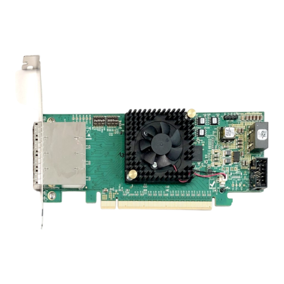
- Page 1 PCIe x16 Gen4 Cable Adapter Model: OSS-PCIe-HIB616-x16 PCIe x16 Gen4 Cable Adapter SKU: OSS-PCIe-HIB616-x16 www.onestopsystems.com...
-
Page 2: Table Of Contents
OSS-PCIe-HIB616-x16 card SFF-8644 Gen4x4 Cable Expansion Chassis / Gen4 Backplane Host Card Mode Configuration Target Card Mode Configuration 2.5.1 Target mode switch settings - OSS-Backplane 2.5.2 Target mode switch settings - Magma-Backplane Supported Use Cases Not Supported Setup 2.7.1 Host-to-Host 2.7.2... - Page 3 Windows 10 / Server Software Installation Troubleshooting Device is not detected or recognized. Broken OSS-518 Board Intermittent start up issue and PCIe cards are not getting recognized. Third Party Hardware and Software Support There is no LINK between Host and Target...
-
Page 4: Preface
One Stop Systems Preface Advisories Five types of advisories are used throughout this manual to provide helpful information, or to alert you to the potential for hardware damage or personal injury. NOTE Used to amplify or explain a comment related to procedural steps or text. IMPORTANT Used to indicate an important piece of information or special “tip”... -
Page 5: Safety Instructions
One Stop Systems Disclaimer: We have attempted to identify most situations that may pose a danger, warning, or caution condition in this manual. However, the company does not claim to have covered all situations that might require the use of a Caution, Warning, or Danger indicator. Safety Instructions Always use caution when servicing any electrical component. - Page 6 One Stop Systems Protecting Against Electrostatic Discharge Electrostatic Discharge (ESD) Warning Electrostatic Discharge (ESD) is the enemy of semiconductor devices. You should always take precautions to eliminate any electrostatic charge from your body and clothing before touching any semiconductor device or card by using an electrostatic wrist strap and/or rubber mat.
-
Page 7: Introduction
PCIe x16 Gen 4 HIB (Host Interface Board) with PCIe quad SFF-8644 cable connectors as used in the PCISIG PCI Express External Cable Specification can be configured as x16, two x8, one x8 and two x4 or four cable ports. The cable adapter operates in host and target mode with a DIP switch setting change. Part# OSS-PCIe-HIB616X16 Specifications Item... -
Page 8: Overview Of Hib616-X16
One Stop Systems When ordering the Gen4 x16 PCIe HIB card, use the following part numbers: Part Numbers Description OSS-PCIe-HIB616-x16(main part#) HIB616-x16 Host Configuration with Full-height bracket OSS-PCIe-HIB616-x16-Half HIB616-x16 Host Configuration with Half-height bracket OSS-PCIe-HIB616-x16-T HIB616-x16 Target configuration with Full-height bracket... -
Page 9: Hib Card Seated Flat (Horizontal Position)
One Stop Systems 1.2.2 HIB card seated flat (horizontal position) 1.2.3 HIB card seated in a vertical position HIB616x16 (Rev B) |9... -
Page 10: Hib Block Diagrams
One Stop Systems 1.2.4 HIB Block Diagrams Target Card Host card HIB616x16 (Rev B) |10... -
Page 11: 0Ss-518 Card Edge X16 Connector
One Stop Systems 1.2.5 0SS-518 Card Edge x16 Connector Diagram below shows the pin out assignments on the OSS-518 card edge x16 connector. HIB616x16 (Rev B) |11... -
Page 12: Pin Out Assignments Of The Sff-8644 Pcb Connectors
One Stop Systems 1.2.6 Pin out assignments of the SFF-8644 PCB Connectors Connector 0 and 1 Connector 2 and 3 HIB616x16 (Rev B) |12... -
Page 13: Signal Descriptions
One Stop Systems 1.2.7 Signal Descriptions PETpN/PETnN: PCI Express Transmitter pairs, labeled where N is the Lane number (starting with 0); “p” is the true signal while “n” is the complement signal. PERpN/PERnN: PCI Express Receiver pairs, labeled where N is the Lane number (starting with 0); “p” is the true signal while “n” is the complement signal. -
Page 14: Dimensions
One Stop Systems Dimensions HIB616x16 (Rev B) |14... -
Page 15: Hardware Requirements
A pair of HIB616-x16 card, one is configured as a host card and the other is configured as a target card. SFF-8644 Gen4x4 Cable This passive copper cable mates to the SFF-8644 connectors on the HIB6xx family of OSS host interface board. •... -
Page 16: Expansion Chassis / Gen4 Backplane
One Stop Systems Expansion Chassis / Gen4 Backplane The OSS HBA (Host Bus Adapter) card must be used in pair and will work properly with an OSS expansion backplane. Host Card Mode Configuration x16 Dip switch Settings: • SW1 #2 = ON; #5 =ON. -
Page 17: Target Card Mode Configuration
SW2 = All OFF 2.5.1 Target mode switch settings - OSS-Backplane Use the switch settings below when using the OSS backplane. 2.5.2 Target mode switch settings - Magma-Backplane When using the legacy or Magma backplane, use the switch settings below for Target mode. -
Page 18: Supported Use Cases
This is not supported. However, this configuration may work with appropriate switch confirmation. The OSS- 518 cards typically outputs REFCLK on pins A6 and A7 which is not PCI standard. This can be changed by using the OSS switch (SW1-4). The OSS-518 outputs POWER_ON signal on a Reserved PCI pin. -
Page 19: Installation Procedures
The following steps will guide you through the installation of your OSS HIB616-x16 card. Tools Required for Installation To complete the installation of the OSS product you will need a Phillips-head screwdriver and ESD wrist strap to prevent electrostatic discharge. Configure Cards (Host and Target modes) Set the switches on the card for the desired operating mode. -
Page 20: Install The Host Card
One Stop Systems Plugin the Target card in the x16 PCIe upstream slot / target slot on the expansion board. Note: Do not plug a Target-configured card in a downstream slot. The Target card will not function in a downstream slot and may cause damage. -
Page 21: Connecting The Link Cables
One Stop Systems The photos below are reference of a x16 PCIe 3.0 slot connector. The specification of the PCIe slot is printed on the board next to connector for easy identification. Connecting the Link Cables 3.5.1 x16 configuration: FOUR cables Note: Make sure the HIB616-x16 host card is set to x16 configuration, see the x16 switch setting section. -
Page 22: X8 Configuration: Two Cables
One Stop Systems 3.5.2 x8 configuration: TWO cables Note: Make sure the HIB616-x16 host card is set to x8 configuration, see x8 switch setting section. • Plug-in the 1 cable to Port#0 (Top port) on both Target and Host cards •... -
Page 23: X4 Configuration: One Cable
One Stop Systems Note: The two cables on the TARGET card must remain connected on PORT #0 and PORT #1. See diagrams below as an example. 3.5.3 x4 Configuration: ONE cable • Plug-in the single cable to Port#0 (Top port) on both Target and Host cards You can move the x4 cable on the HOST card to another port. -
Page 24: Disconnecting The Cable
One Stop Systems Photo C1: Cable on the Target card is connected PORT #0. The other end of the cable is connected to PORT #3 on the Host card. Diagrams below are different “x4” cable configurations. 3.5.4 Disconnecting the cable To disconnect the link cable, pull back the PLASTIC thumb tab to release metal pins while slowly pulling the cable out. -
Page 25: Connect Power To Expansion Board / Unit
One Stop Systems Connect Power to Expansion board / unit Plug in the power cable to the expansion unit power supplies. • All three fans will spin up at low speed (if you have an expansion unit equipped with cooling fans). •... -
Page 26: Power Up The Host Computer
One Stop Systems Power UP the Host Computer Upon “powering UP” the host computer. Three more LEDs on the Host card will illuminate. Host card CE: Solid green PWR: Blinking 7x + pause CHO -LINK LED: Solid green Both Target and Host cards will have the LINK LED illuminate as solid green. The LINK LED indicator will vary depending on the PCIe Slot Generation configured in the BIOS. -
Page 27: Led Definition
One Stop Systems 3.10 LED Definition 3.10.1 x16, x8 and x4 LED Indicators x16, x8 and x4 cable-configurations will have the same LED indicators. Status Description CH0 (D1) ON (Solid Green) Link LED. There is a link between Host and Target cards LED3, LED2, LED1 &... -
Page 28: Hardware & Technical Info
One Stop Systems Hardware & Technical Info LED Definitions Descriptions Status (Solid Green, OFF, Blinking) D1 (CHO) Cable Link LED Solid Gen4, Blink 2Hz is Gen3, 1Hz is Gen2, 0.5Hz is Gen1 D3 (CH1) Cable Link LED Solid Gen4, Blink 2Hz is Gen3, 1Hz is Gen2, 0.5Hz is Gen1 D5 (CH2) Cable Link LED Solid Gen4, Blink 2Hz is Gen3, 1Hz is Gen2, 0.5Hz is Gen1... -
Page 29: Standard & Bifurcated Configurations
One Stop Systems Standard & Bifurcated Configurations 4.3.1 Standard Configurations • x16: Using four Gen4 SFF-8644 cables. When using a x16 standard configuration, the host card dipswitches must be set to x16 host mode. Make sure the Target card is set to Target mode. •... -
Page 30: Hba Bifurcated Configurations
/ branch. Basically, dividing the HBA PCIe link width to smaller chunks/branches. Example, the OSS HBA x16 card could be bifurcated into four (4) x4 i.e., x4, x4, x4, x4 OR two (2) x8 i.e., x8, x8. -
Page 31: X8, X8 Bifurcation Configuration
One Stop Systems 4.3.3 x8, x8 Bifurcation Configuration: OSS-518 Bifurcated to x8, x8: One Host card ----->connected to two Target cards. • Requires no special FW image. • You need to set the dipswitches on the host card accordingly based on the bifurcation mode. Use the setting below for the host card. -
Page 32: X4, X4, X4, X4 Bifurcation Configuration
One Stop Systems 4.3.4 x4, x4, x4, x4 Bifurcation Configuration OSS-518 Bifurcated to x4, x4, x4, x4: One Host card------>connected to four Target cards. • Requires no special FW image. • You need to set the dipswitches on the host card accordingly based on the bifurcation mode. Use the setting below for the host card. - Page 33 One Stop Systems x8, x4, x4 Configuration: This is supported. The board firmware does not to support x8, x4, x4. HIB616x16 (Rev B) |33...
-
Page 34: Bifurcation Setup
One Stop Systems Bifurcation Setup It is important to use the same model of OSS HBA Gen4 cards. Set the Host card dipswitch to either x8, x8 or to x4, x4, x4, x4. See dipswitch setting above for different HBA bifurcation modes. -
Page 35: Identify Hib Device
#lspci –tv | grep c010 The c010 is the Device number of the card. The output below gives you tree-like structure of the OSS Host card + Target card and OSS-5slot backplane. In this setup the Target card is installed in a 5slot backplane (OSS-580) with a PCIe switch that has the same Device ID of c010. - Page 36 One Stop Systems To check on the PCIe Gen speed and Link Width • #lspci –nvvs b8:00.00 | grep ‘LnkCap\|LnkSta’ To display more details or information Use command lspci -nvvs 1e:00.0. You can change the 1e:00.0 to whatever the PCI Device number in your system. •...
- Page 37 One Stop Systems You can check the Host and Target devices by using the command below. • #lspci –vvv | grep c010 The output below shows only the Host card is detected. The Host card is not connected to the Target card / expansion unit. •...
-
Page 38: Windows 10 / Server
One Stop Systems Windows 10 / Server Verify hardware device in Windows Operating System. As your Windows computer starts up, you will see a small message box pop-up in the lower-right corner of the screen to alert you that Windows has found new hardware. To verify a successful installation on Windows, find the ‘My Computer’... - Page 39 One Stop Systems These are the screenshots of Windows Device Manager running Windows 10. • Photo below is showing multiple layers of PCI standard PCI-to-PCI bridges. • Displaying a link between Host and Target cards. Showing a PCIe device (i.e., NVIDIA card) is recognized. The PCIe device is the 3 party PCIe card installed into the downstream slot of an expansion backplane.
-
Page 40: Software Installation
One Stop Systems Software Installation No software or driver is required for the HIB68-x16 card. HIB616x16 (Rev B) |40... -
Page 41: Troubleshooting
Unplug all power from the host computer and expansion unit and reconnect it. Turn the expansion unit ON first before the host computer. If you have replaced the link cables, OSS target and host cards and still experiencing the problem, try a different known-good computer. -
Page 42: Third Party Hardware And Software Support
OSS reserves the right to request that the third-party hardware or software be removed. If OSS identify that the OSS product is fully functional and the root cause or the problem is related to third-party hardware or software, customer / end-user will reach out to third-party vendor for assistance or will be responsible to further troubleshoot the issue. -
Page 43: How To Get More Help
We test, certify, and support many third-party hardware and software products along with OSS hardware and are happy to integrate a fully supported system. Ask us about that service and we would be happy to help. If an OSS product is fully functional and a support issue is related to third-party hardware or software that did not ship from the OSS factory, the customer requesting support should reach out to the third-party vendor for assistance to fully troubleshoot the issue. -
Page 44: Online Support Resources
One Stop Systems Online Support Resources As a product user and customer, listed below are our Online Support Resources https://www.onestopsystems.com/support provides Knowledgebase Articles such as troubleshooting methods, compatibility, FAQ, documentation, and product technical information. If you need technical support, product assistance or have a technical inquiry we encourage you to submit it on-line using our Technical Support Form. - Page 45 One Stop Systems HIB616x16 (Rev B) |45...
Need help?
Do you have a question about the OSS-PCIe-HIB616-x16 and is the answer not in the manual?
Questions and answers