
Subscribe to Our Youtube Channel
Related Manuals for OSS OSS-KIT-EXP-61611-xM


Summary of Contents for OSS OSS-KIT-EXP-61611-xM
- Page 1 PCIe x16 Gen4 Host to Target Kit (61611) Model: OSS-KIT-EXP-61611-xM PCIe x16 Gen4 Host to Target Kit- Installation Manual SKU: OSS-KIT-EXP-61611-XM www.onestopsystems.com...
-
Page 2: Table Of Contents
OSS-PCIe-HIB616-x16 card SFF-8644 Gen4 x4 Cable Expansion Chassis / Gen4 Backplane Host Card Mode Configuration Target Card Mode Configuration 2.5.1 Target mode switch settings - OSS-Backplane 2.5.2 Target mode switch settings - Magma-Backplane Supported Setup Use Cases / Configurations 2.7.1 Host-to-Host 2.7.2... - Page 3 Intermittent start up issue and PCIe cards are not getting recognized Third Party Hardware and Software Support There is no LINK between Host and Target Does the OSS-518 board (Gen4 PCIe x16 Adapter card) support CMI Operation (Remote Power Power ON)? How to Get More Help Contacting Technical Support Returning Merchandise Third Party Hardware &...
-
Page 4: Preface
Disclaimer: We have attempted to identify most situations that may pose a danger, warning, or caution condition in this manual. However, the company does not claim to have covered all situations that might require the use of a Caution, Warning, or Danger indicator. OSS-KIT-EXP-61611-XM | 4... -
Page 5: Safety Instructions
Also, before connecting a cable, make sure both connectors are correctly oriented and aligned. CAUTION Do not attempt to service the system yourself except as explained in this manual. Follow installation instructions closely. OSS-KIT-EXP-61611-XM | 5... - Page 6 Handle all sensitive components at an ESD workstation. If possible, use anti-static floor pads and workbench pads. Handle components and boards with care. Do not touch the components or contacts on a board. Hold a board by its edges or by its metal mounting bracket. OSS-KIT-EXP-61611-XM | 6...
-
Page 7: Introduction
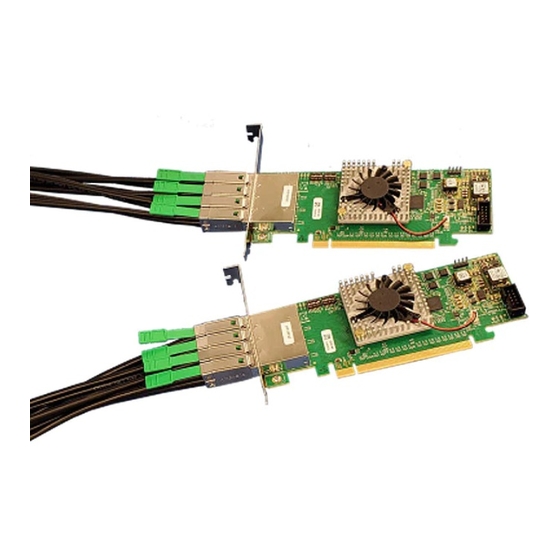
Introduction The PCIe x16 Gen 4 expansion kit connects a server to an OSS Expansion Backplane. It is composed of a “Gen4 Mini-HD SFF-8644 PCIe cable (SKU# OSS-mSAS-CBL-x4-C-XM)” and two “PCIe x16 Gen 4 Cable Adapter (SKU: OSS- PCIe-HIB616-x16)”. The PCIe x16 Gen 4 host cable adapter plugs into a server and cables to a PCIe x16 Gen 4 switch-based target cable adapter. The expansion kit connects with up to (4) x4, 1 meter SFF-8644 PCIe Gen 4 compliant cables. -
Page 8: Parts Of Hib616-X16
One Stop Systems When ordering the Gen4 x16 PCIe HIB card and Gen4 SFF-8644 PCIe cable, use the following part numbers: Part Numbers Description OSS-PCIe-HIB616-x16 ( main part#) HIB616-x16 Host Configuration with Full-height bracket OSS-PCIe-HIB616-x16-Half HIB616-x16 Host Configuration with Half-height bracket... -
Page 9: Hib Card Seated Flat (Horizontal Position)
One Stop Systems 1.2.2 HIB card seated flat (horizontal position) 1.2.3 HIB card seated in a vertical position OSS-KIT-EXP-61611-XM | 9... -
Page 10: 1.2.4 Hib Block Diagrams
One Stop Systems 1.2.4 HIB Block Diagrams Target Card Host card OSS-KIT-EXP-61611-XM | 10... -
Page 11: Pin Out Assignments Of The Sff-8644 Pcb Connectors
One Stop Systems 1.2.5 Pin out assignments of the SFF-8644 PCB Connectors Connector 0 and 1 Connector 2 and 3 OSS-KIT-EXP-61611-XM | 11... -
Page 12: Signal Descriptions
Operates at up to 256Gb/s at PCIe Gen4 speeds. No driver required. Uses mini-SAS HD or PCIe SFF-8644 cables. Simplified cabling with a point-to-point, serial architecture. Operates in Host and Target modes Support PCIe Bifurcation OSS-KIT-EXP-61611-XM | 12... -
Page 13: Sff-8644 Pcie Cable
SFF-8644 PCIe cable Gen4 High speed signaling cable up to 3m in length. This passive copper cable mates to the SFF-8644 connectors on the HIB6xx family of OSS host interface boards and includes the CMI (cable management interface) and serialized EEPROMs in the cable backshell. -
Page 14: Hardware Requirements
A pair of HIB616-x16 card, one is configured as a host card and the other is configured as a target card. SFF-8644 Gen4 x4 Cable This passive copper cable mates to the SFF-8644 connectors on the HIB6xx family of OSS host interface board. ... -
Page 15: Host Card Mode Configuration
SW1 #2 = ON; #5 = ON SW2 #1 = OFF; #2 = ON or #2 = OFF and #1 = ON x4 Dip switch Settings SW1 #2 = ON; #5 = ON SW2 = All OFF OSS-KIT-EXP-61611-XM | 15... -
Page 16: Target Card Mode Configuration
SW2 = All OFF 2.5.1 Target mode switch settings - OSS-Backplane Use the switch settings below when using the OSS backplane. 2.5.2 Target mode switch settings - Magma-Backplane When using the legacy or Magma backplane, use the switch settings below for Target mode If Target card is not linking up, you can set SW1-5 to ON position, see photo below. -
Page 17: Supported Setup
Using a set of OSS-PCIe-HIB616-x16 card (Target and Host cards), OSS Gen4 backplane and PCIe Gen4 cables. Use Cases / Configurations 2.8.1 Host-to-Host This configuration is supported. The OSS-518 board (HIB616-x16 card) is not programmed for this option nor will it work from hardware standpoint. OSS-KIT-EXP-61611-XM | 17... -
Page 18: Using 3 Rd Party Target Backplane
This configuration can be supported with appropriate switch confirmation. The OSS- 518 card typically outputs REFCLK on pins A6 and A7 which is not PCI standard. This can be changed by using the OSS switch (SW1-4). The OSS-518 outputs POWER_ON signal on a Reserved PCI pin. -
Page 19: Installation Procedures
The following steps will guide you through the installation of your OSS HIB616-x16 card. Tools Required for Installation To complete the installation of the OSS product you will need a Phillips-head screwdriver and ESD wrist strap to prevent electrostatic discharge. Configure Card to Host and Target modes Set the switches on the card for the desired operating mode. - Page 20 Install the Target card in the x16 PCIe upstream slot / target slot on the expansion board. Note: Do not plug a Target-configured card in a downstream slot. The Target card will not function in a downstream slot and may cause damage. Secure the card by screwing the card-bracket to the chassis. OSS-KIT-EXP-61611-XM | 20...
-
Page 21: Install The Host Card
The photos below are reference of a x16 PCIe slot connector. Below example is a photo of a PCI-E 3.0 x16 slot. The specification of the PCIe slot is printed on the board next to connector for easy identification. OSS-KIT-EXP-61611-XM | 21... -
Page 22: Connecting The Link Cables
Note: Make sure the HIB616-x16 host card is set to x8 configuration, see x8 switch setting section. Plug-in the 1 cable to Port#0 (Top port) on both Target and Host cards Plug-in the 2 cable to Port#1 on both Target and Host cards. OSS-KIT-EXP-61611-XM | 22... -
Page 23: X4 Configuration: One Cable
You can move the x4 cable on the HOST card to another port. However, the other end of the cable stays connected to PORT#0 on the Target card. Photo A1: Cable on the Target card isconnected to PORT #0. The other end of the cable is connected to PORT #1 on the Host card. OSS-KIT-EXP-61611-XM | 23... - Page 24 Photo B1: Cable on the Target card is connected to PORT #0. The other end of the cable is connected to PORT #2 on the Host card. Photo C1: Cable on the Target card is connected PORT #0. The other end of the cable is connected to PORT #3 on the Host card. Diagrams below are different x4 cable configurations. OSS-KIT-EXP-61611-XM | 24...
-
Page 25: Disconnecting The Cable
LED1, LED2, LED3, LED4, PWR and CE LEDS: AUX LED Stand-by Mode LED: During “Stand-by Mode” (awaiting to power ON) you will only see four LEDs on the Host and Target cards. These are the LED1, LED2, LED3 and LED4. OSS-KIT-EXP-61611-XM | 25... -
Page 26: Turn On The Host Computer
Blinking Green: The CARD EDGE connector is communicating to Gen3 PCIe switch on the expansion board / backplane. Solid Green: Gen 4 on the expansion chassis switch ON (Blinking Green) Power Good / FPGA Healthy ON (Solid Green) AUX Power Good OSS-KIT-EXP-61611-XM | 26... -
Page 27: X8 Configuration Leds (Two Cables)
Blinking Green: The CARD EDGE connector is communicating to Gen3 PCIe switch on the expansion board / backplane. Solid Green: Gen 4 on the expansion chassis switch ON (Blinking Green) Power Good / FPGA Healthy ON (Solid Green) AUX Power Good OSS-KIT-EXP-61611-XM | 27... - Page 28 Solid Green: Gen 4 on the expansion chassis switch Blinking Green: The CARD EDGE connector is communicating to Gen3 PCIe switch on the expansion board / backplane. ON (Blinking Green) Power Good / FPGA Healthy ON (Solid Green) AUX Power Good OSS-KIT-EXP-61611-XM | 28...
-
Page 29: X4 Configuration Leds (One Cable)
The Photo below is the link LED on the Host card, set to x4 and with single cable connected to top PORT #0. Photo below is the link LED on the Host card, set to x4 and with single cable connected to PORT #1. OSS-KIT-EXP-61611-XM | 29... - Page 30 Power Good / FPGA Healthy ON (Solid Green) AUX Power Good DANGER or STOP Do not remove or uninstall the Host and Target cards while the system is ON. Turn OFF the system first before uninstalling the cards. OSS-KIT-EXP-61611-XM | 30...
-
Page 31: Hardware & Technical Info
Debug LED – would be used for CMI Not defined, always on Dipswitch Settings SW1-5 must always be ON. Auto mode not supported SW2-3 to 6 is not used. Legacy backplane: Magma Gen3 backplane OSS-KIT-EXP-61611-XM | 31... -
Page 32: Standard & Bifurcated Configurations
One Stop Systems Standard & Bifurcated Configurations 4.3.1 Standard Configurations x16: Using four Gen4 SFF-8644 cables Using two Gen4 SFF-8644 cables Using a single SFF-8644 cable OSS-KIT-EXP-61611-XM | 32... -
Page 33: Bifurcated Configurations
One Stop Systems 4.3.2 Bifurcated configurations x8, x8 Configuration: This is supported x4, x4 Configuration: This is supported OSS-KIT-EXP-61611-XM | 33... - Page 34 One Stop Systems x4, x4, x4, x4 Configuration: This is supported x4, x4, x4 Configuration: This is supported OSS-KIT-EXP-61611-XM | 34...
- Page 35 One Stop Systems x8, x4, x4 Configuration: This is supported. The firmware is not programmed in the board to support x8,x4,x4 X8, x4 Configuration: This is supported but it will just down train to x4 OSS-KIT-EXP-61611-XM | 35...
-
Page 36: Identify Hib Device
To check on the revision of the card, use the command below. #lspci –vmms ac:00.0 See output below. To check on the PCIe Gen speed and Link Width #lspci –nvvs b8:00.00 | grep ‘LnkCap\|LnkSta’ OSS-KIT-EXP-61611-XM | 36... - Page 37 One Stop Systems To display more details or information lspci –nvvs ac:00.00 OSS-KIT-EXP-61611-XM | 37...
- Page 38 The output below shows only the Host is being detected. The Host card is not connected to the Target card. To check or to identify whether the bus XX:XX.0 is the Upstream port and Downstream port, on the terminal window type lspci –s ac:00.0 - vvv | grep ‘Capabilities\|Port\|LnkSta\|LnkCap’ or lspci –nvvs –ac:00.00 | grep ‘Capabilities\|Port\|LnkSta\|LnkCap’ OSS-KIT-EXP-61611-XM | 38...
-
Page 39: Windows 10 / Server
The photo below is showing multiple layers of PCI Express standard Upstream Switch Port and PCI Express standard Downstream Switch Port. Displaying a link between Host and Target cards. Photo below is only showing a single Host device is detected. These are the screenshots of Windows Device Manager running Windows 10. OSS-KIT-EXP-61611-XM | 39... - Page 40 Displaying a link between Host and Target cards. Showing a PCIe device (i.e NVIDIA card) is recognized. The PCIe device is the 3 party PCIe card installed into the downstream slot of an expansion backplane. The screenshot below depicts that only the Host card is detected. OSS-KIT-EXP-61611-XM | 40...
-
Page 41: Software Installation
One Stop Systems Software Installation No software or driver is required for the HIB616-x16 card. OSS-KIT-EXP-61611-XM | 41... -
Page 42: Troubleshooting
Broken OSS-518 Board If you received a brand new DOA (Dead on Arrival) board, please contact OSS to RMA board and request for a replacement. If you have an out of warranty board, please contact OSS Sales team and buy a new replacement board. -
Page 43: Third Party Hardware And Software Support
In order to isolate the issue, OSS reserves the right to request that the third-party hardware or software be removed. If OSS identify that the OSS product is fully functional and the root cause or the problem is related to third-party hardware or software, customer / end-user will reach out to third-party vendor for assistance or will be responsible to further troubleshoot the issue. -
Page 44: How To Get More Help
We test, certify and support many third party hardware and software products along with OSS hardware and are happy to integrate a fully supported system. Ask us about that service and we would be happy to help. If an OSS product is fully functional and a support issue is related to third-party hardware or software that did not ship from the OSS factory, the customer requesting support should reach out to the third- party vendor for assistance to fully troubleshoot the issue. -
Page 45: Online Support Resources
If you need technical support, product assistance or have a technical inquiry we encourage you to submit it on-line using our Technical Support Form. If you need to send a unit for repair or diagnostic evaluation, fill out our RMA (Return Material Authorization) online request form. https://www.onestopsystems.com/support OSS-KIT-EXP-61611-XM | 45... - Page 46 One Stop Systems OSS-KIT-EXP-61611-XM | 46...
Need help?
Do you have a question about the OSS-KIT-EXP-61611-xM and is the answer not in the manual?
Questions and answers