
Subscribe to Our Youtube Channel
Related Manuals for OSS OSS-PCIe-HIB38-x16


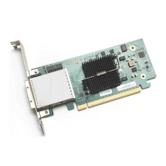
Summary of Contents for OSS OSS-PCIe-HIB38-x16
- Page 1 PCIe x16 Gen3 iPass Cable Adapter Model: OSS-PCIe-HIB38-x16 PCIe x16 Gen3 iPass Cable Adapter SKU: OSS-PCIe-HIB38-x16 www.onestopsystems.com...
-
Page 2: Table Of Contents
Install HIB Target card Connect the x16 iPass Cable 3.4.1 Disconnecting the cable Software Installation Verify Hardware Bracket LED Status indicators Troubleshooting How to Get More Help 7.1 Contacting Technical Support 7.2 Returning Merchandise 7.3 Online Support Resources OSS-PCIe-HIB38-x16| 2... -
Page 3: Preface
Disclaimer: We have attempted to identify most situations that may pose a danger, warning, or caution condition in this manual. However, the company does not claim to have covered all situations that might require the use of a Caution, Warning, or Danger indicator. OSS-PCIe-HIB38-x16| 3... -
Page 4: Safety Instructions
Also, before connecting a cable, make sure both connectors are correctly oriented and aligned. CAUTION Do not attempt to service the system yourself except as explained in this manual. Follow installation instructions closely. OSS-PCIe-HIB38-x16| 4... - Page 5 Handle all sensitive components at an ESD workstation. If possible, use anti-static floor pads and workbench pads. Handle components and boards with care. Do not touch the components or contacts on a board. Hold a board by its edges or by its metal mounting bracket. OSS-PCIe-HIB38-x16| 5...
-
Page 6: Introduction
PCIe bus at 120Gb/s with extremely low latency because there is no conversion software. Part numbers: OSS-PCIe-HIB38-x16-H (Host Adapter) OSS-PCIe-HIB38-x16-H-F (Host Adapter, Full Height bracket) OSS-PCIe-HIB38-x16-H-H (Host Adapter, Half Height bracket) OSS-PCIe-HIB38-x16-T (Target Adapter) OSS-PCIe-HIB38-x16-T-F (Target Adapter, Full Height) -
Page 7: Block Diagram
One Stop Systems Block Diagram Overview OSS-PCIe-HIB38-x16| 7... -
Page 8: Dimension
Power is provided by the PCI-e card slot. Power required by internal components of OSS-PCIe-HIB-38-x16 is estimated to be 15 watts when both ports are fully linked and operating in Gen3 mode. Cable power is to be provided per PCIe cable specification. When an active cable (powered transceiver) is used, additional power is required from the PCI-e card slot. -
Page 9: Pcie Cable Sideband Signals
Note that the PEX8733’s upstream port is set to 8 by the mode 1 eeprom. The upstream system provides a copy of its SSC, and the on-board buffer provides a copy to the downstream target as well as the PEX8733’s core logic. OSS-PCIe-HIB38-x16| 9... - Page 10 One Stop Systems Mode 2: Host Mode. In this mode, the PCI-e cable is connected to a downstream (target) or the cable port of a Mode 0 OSS-PCIe- HIB-38-x16, while the card edge interface is installed in an upstream host system. The host system’s SSC is used to provide the PEX8733 core logic clock as well as the cable’s reference clock.
-
Page 11: Pin Assignments
PoWer: Provides local power for in-cable redriver circuits. Only needed on long cables. Power does not go across the cable PWR_RTN PoWer ReTurn: Provides local power return path for PWR pins. CWAKE# Cable Wake CPERST# Cable PCi Express Reset OSS-PCIe-HIB38-x16| 11... -
Page 12: Hardware & Software Requirements
OSS Expansion chassis or OSS expansion board / backplane x16 Gen 3 You need an expansion chassis with Gen3 backplane . Photos below are example of Gen3 OSS backplanes and an expansion unit. The HIB card has custom pinout unique to OSS and only OSS Target adapters will work in the upstream slot of our expansion backplanes. -
Page 13: Software
OSS-370 boar card requires no driver or software on Windows based OS and Linux. Tools Required for Installation To complete the installation of the OSS product you will need a Phillips-head screwdriver and ESD wrist strap to prevent electrostatic discharge. OSS-PCIe-HIB38-x16| 13... -
Page 14: Installation Procedures
Target adapter (aka: Target Card, Expansion Interface Card) The target card(Part# OSS-PCIe-HIB38-x16-T) fits into an OSS custom slot backplane and extends the PCIe bus to a single add-in board via a PCIe x16 cable. The “Target Card” can only be installed in a designated “Upstream slot” on OSS expansion backplane. -
Page 15: Install Hib Host Card
Detach the standard bracket from the card, and place the low profile bracket and secure it. Use proper ESD procedures when completing this action. Install the host card in the computer. Plug in the host card in the x16 Gen3 PCIe slot. Secure the card. OSS-PCIe-HIB38-x16| 15... -
Page 16: Install Hib Target Card
Install HIB Target card Install the Target card in OSS expansion backplane. Plug-in the target card in the designated Upstream slot of the backplane. The HIB Target card will only work in the OSS backplane designated Upstream slot. Below photos are example of Gen3 OSS expansion backplanes showing where the location of the Upstream slot. -
Page 17: Connect The X16 Ipass Cable
Insert the cable connector into the connector shell on the board until the connector teeth snap securely into the holes in the cable shell. See photos below. Connect cable to Host adapter card, which is installed in the computer. OSS-PCIe-HIB38-x16| 17... -
Page 18: Disconnecting The Cable
One Stop Systems Connect the other end of the cable to the Target card, which is installed in the OSS expansion chassis, see photos below 3.4.1 Disconnecting the cable To remove the cable, pull down the green plastic tab or push the metal tab and slowly pull the cable out... -
Page 19: Software Installation
One Stop Systems Software Installation Install the appropriate software / driver for the M.2 device. OSS does not provide the driver / software for the M.2 device. This can be obtained or downloaded from the manufacturer’s website. When done installing the driver, reboot the host computer. -
Page 20: Verify Hardware
EDGE LED shows: HOST card – connection between host card and host system. TARGET card – connection between the switch on the target card and the switch in the expansion chassis PWRGD LED shows electrical power is present OSS-PCIe-HIB38-x16| 20... -
Page 21: Troubleshooting
If you are still having problem, do the following Try another expansion chassis or backplane Replace the cable Replace the Host card Replace the target card Contact OSS Customer / Technical Support. You may need to send the boards or expansion chassis for service. OSS-PCIe-HIB38-x16| 21... -
Page 22: How To Get More Help
If you need technical support, product assistance or have a technical inquiry we encourage you to submit it on-line using our Technical Support Form. If you need to send a unit for repair or diagnostic evaluation, fill out our RMA (Return Material Authorization) online request form. https://www.onestopsystems.com/support OSS-PCIe-HIB38-x16| 22... - Page 23 One Stop Systems OSS-PCIe-HIB38-x16| 23...
Need help?
Do you have a question about the OSS-PCIe-HIB38-x16 and is the answer not in the manual?
Questions and answers