
Related Manuals for OSS OSS-PCIE-4UV-5slot


Summary of Contents for OSS OSS-PCIE-4UV-5slot
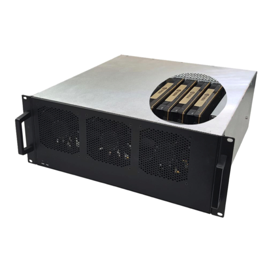
- Page 1 4U Value GPU Accelerator Gen3 5 PCIe (3.0 x16)Slot Expansion System User Manual SKU: OSS-PCIE-4UV-5slot www.onestopsystems.com...
-
Page 2: Table Of Contents
One Stop Systems Table of Contents Preface ....................................7 Advisories ..........................................7 Safety Instructions ....................................... 8 Protecting Against Electrostatic Discharge ................................9 Introduction ..................................10 General Specification ....................................10 Features ........................................11 Block Diagram ......................................11 1.3.1 Enclosure ...................................... 11 1.3.2 Backplane ..................................... - Page 3 How to verify system on Windows OS (i.e.Windows Server)......................27 5.2.2 PCIe slot and Device ID assignment .............................. 29 5.2.3 How to verify 457 OSS unit in Linux OS ............................32 5.2.4 PCIe slot and Port# assignment ..............................35 5.2.5 Linux Commands to check on expansion device...........................
- Page 4 OSS-457 Backplane....................................62 8.2.1 PCIe Slots and Ports Assignment ..............................62 8.2.2 Dimension ....................................62 8.2.3 Parts of OSS-457 backplane ................................63 8.2.4 Card Slot Link LEDs ..................................64 8.2.5 Slot Type ....................................... 64 8.2.6 Force Power ON ................................... 65 Using Fiber Optic Cables and HIB68-x16 card ............................
- Page 5 One Stop Systems Fan Controller ................................82 Specifications ......................................83 Troubleshooting ................................84 10.1 Locating the Problem ..................................84 10.1.1 Windows ...................................... 84 10.1.2 Linux ......................................84 10.1.3 Mac ......................................85 10.2 My Computer Cannot Find the PCIe Expansion System ........................85 10.3 My Computer Hangs During Power Up ..............................
- Page 6 One Stop Systems 4U Value 5slot G3 Expansion Unit...
-
Page 7: Preface
One Stop Systems Preface Advisories Five types of advisories are used throughout this manual to provide helpful information, or to alert you to the potential for hardware damage or personal injury. Disclaimer: We have attempted to identify most situations that may pose a danger, warning, or caution condition in this manual. However, One Stop Systems does not claim to have covered all situations that might require the use of a Caution, Warning, or Danger indicator. -
Page 8: Safety Instructions
One Stop Systems Safety Instructions Always use caution when servicing any electrical component. Before handling the One Stop Systems Expansion chassis, read the following instructions and safety guidelines to prevent damage to the product and to ensure your own personal safety. Refer to the “Advisories” section for advisory conventions used in this manual, including the distinction between Danger, Warning, Caution, Important, and Note. -
Page 9: Protecting Against Electrostatic Discharge
One Stop Systems Protecting Against Electrostatic Discharge Electrostatic Discharge (ESD) Warning Electrostatic Discharge (ESD) is the enemy of semiconductor devices. You should always take precautions to eliminate any electrostatic charge from your body and clothing before touching any semiconductor device or card by using an electrostatic wrist strap and/or rubber mat. -
Page 10: Introduction
Half Height, half length, single slot x16 PCIe add-in card form factor PCIe3 x16 physical card edge connector (128Gbps) Backplane: One OSS-PCIe3-BP-5Slot-5x16(457 board) - PCIe 3 5-slot expansion backplane Enclosure: -Supports up to 5 full-height, full-length PCIe slots plus 2 cable interfaces in 10-2 configuration. -
Page 11: Features
One Stop Systems Features 4U rackmount design 5 PCIe 3.0 x16 expansion slots Single PCIe 3.0 x16 host connections One Ipass or Four Mini SAS x4 Cables PWM fan options Two 2000W load-sharing power supplies or Single AUX power connectors for high power AICs Block Diagram 1.3.1 Enclosure... -
Page 12: Backplane
One Stop Systems Rear View 1.3.2 Backplane 1.3.3 Host and 5-slot backplane 4U Value 5slot G3 Expansion Unit... -
Page 13: Supported Configuration
One Stop Systems Supported Configuration Attached to one host server / computer. Two Cable adapter cards: One in the expansion unit and the other in the host system. Main Components The 4U Value 5-slot GPU Accelerator System is composed of following major components One 5-slot Backplanes One Target Card : PCIe 3.0 x16 One Host Card: PCIe 3.0 x16... -
Page 14: Parts
One Stop Systems Parts 4U Value 5slot G3 Expansion Unit... -
Page 15: Pre-Installation Information
One Stop Systems Pre-Installation Information Before using the One Stop Systems expansion unit, you should perform the following steps: Inventory the shipping carton contents for all of the required parts Gather all of the necessary tools required for installation ... -
Page 16: Hardware Set-Up / Installation
One Stop Systems Hardware Set-up / Installation The following steps will guide you through the installation of your One Stop Systems expansion system CAUTION Hardware installation shall be performed only by qualified service personnel per UL and IEC 60950-1. Electrostatic Discharge (ESD) Warning All PCI cards are susceptible to electrostatic discharge. -
Page 17: Before You Begin
One Stop Systems Before you Begin The system’s power supply is auto-switching, it will automatically switch to match whatever source power you are using. The product is shipped with a US/Canadian Standard, 125V or 250V power cord. Remove Top Cover Remove the five (5) mounting screws on top of the chassis. -
Page 18: Install Target Card
Install Target Card By default the “Target card (OSS-PCIe-HIB38-x16-T) ” or Expansion Interface card” is installed in the “Upstream slot” of the expansion backplane. If the Target card is missing, install the target card in the “Upstream slot” (designated slot for Target card only). - Page 19 One Stop Systems If Dipswitches are set correctly, insert the host card into a vacant x16 PCIe slot by gently pushing the card until it is firmly seated, then secure the card to the slot with a mounting screw. See photos below. Photo below shows the cable port on the back of the target card.
-
Page 20: Installation Of Host Card In A Server Using A "Riser Card
One Stop Systems 2.5.1 Installation of host card in a server using a “Riser Card” This section describes on how to install the Host Card via “riser card” in the host computer. Remove the riser card from the computer (see computer manufacturing instructions on how to dismount the riser card). ... -
Page 21: Connect Link Cables
One Stop Systems Connect Link Cables Note: Cables may vary depending on the adapter cards included in the unit. Connect the cable to the Target and Host Interface cards. For proper way of connecting the cable to the interface card, see pictures below. ... -
Page 22: Applying Power Correctly
One Stop Systems Applying Power Correctly Connect Power Cord / Cable Use the power cord supplied with the unit, connect the power cord to the back of the power supply. Ensure that the system’s power supply unit is fully secured before connecting the power cord. You should have either the 125v or the 250v power cord. If you only have the 125V power cord and you require the 250V please contact our Sales Team (sales@onestopsystems.com) to place an order. -
Page 23: Connecting To An Electrical Outlet
Canadian 125V or 250V power supply cord is provided with this product. If you are using a 250V power cord, you would need to connect that to a PDU (power distribution unit). You can buy the PDU on any online electronic stores. OSS does not sell the PDU. -
Page 24: Power On The Expansion Unit
One Stop Systems Power ON The Expansion Unit The expansion system is switched ON by the Host system. A “Power On / Sideband” signal is sent to the cable triggering the expansion system to power ON or OFF. The expansion unit will turn ON automatically upon powering up the Host computer. The two front LEDs (PWR and FAN) will illuminate as “solid-green”. -
Page 25: Hardware Check
One Stop Systems Hardware Check Once the host computer has booted up, check the expansion unit and verify that all LEDs are correctly illuminated. A fully operational expansion chassis will show the following LEDs. LinkUP LED: Target card and Host card, CBL and EDG LEDs both should be illuminated as solid green. ... -
Page 26: Reinstall Top Cover
One Stop Systems Reinstall Top Cover CAUTION Re-install top cover when done checking internal LEDs to allow proper airflow. Front LEDs Status Indicator There are two LED status indicators located on the front of the unit. These two LEDS should be ON as solid green upon powering UP the expansion unit. -
Page 27: Software Installation
One Stop Systems Software Installation Software Driver Installation The 4U Value 5-slot expansion unit requires no driver on Windows 7, Windows 8, Windows 10, Windows Server, Linux, Unix, Centos and Mac OS, which means no installation of software is needed. The only software / driver you would need to install is for the add-in card (your PCIe card). - Page 28 One Stop Systems The screenshots below represent the structure of one 457 OSS board attached to a specific host computer running Windows Server OS. It is either the 1 or 2 backplane attached to a specific host computer. NOTE: If you are not seeing five or ten PCI Express standard Downstream Switch Ports (as shown from the above photos) in Windows Device Manager, try the following troubleshooting steps: ...
-
Page 29: Pcie Slot And Device Id Assignment
One Stop Systems The six PCI Express Switch Ports correspond to the six PCIe slots on each 457 OSS board comprising of one upstream port and five downstream ports. The upstream port is the target slot or upstream slot. - Page 30 The following photos are screenshots of Windows Device Manager showing the slot number and device number for each PCI Express standard Downstream Switch Port. Use this as your reference point on finding which card is plugged into a specific slot on the 457 OSS expansion backplane.
- Page 31 One Stop Systems 4U Value 5slot G3 Expansion Unit...
-
Page 32: How To Verify 457 Oss Unit In Linux Os
There are six PCIe slots per 457 board comprising of five downstream ports and one upstream port. The five downstream ports are the actual PCIe slots on the 457 OSS board in which a PCIe card or GPU card is plugged in. ... - Page 33 One Stop Systems The photo below is the lspci | grep “8796”output of two 457 OSS boards attached to one host computer. It shows twelve instances of 8796 devices / PLXs. See photos below, the first six instances of 8796 devices (top level)are the slots from Board #1. The second six instances of 8796 devices (bottom level) are the slots from Board #2.
- Page 34 One Stop Systems The photo below shows six instances of 8796 devices from OSS-457 backplane. The following photos are example of 457 OSS board slots and their corresponding ports. The first “PCI Bridge” is the Upstream Port / Target slot.
-
Page 35: Pcie Slot And Port# Assignment
One Stop Systems 5.2.4 PCIe slot and Port# assignment On Linux-based OS each PCIe slot on the backplane has a designated Port number (i.e. Port 0), see photo below. On Windows OS, it is called Device ID On Linux OS, it is know as Port#. See following photos. The following photos are screenshots of Linux OS “lspci | grep 8796”... - Page 36 One Stop Systems Slot 2, assigned to PORT #8 Slot 3, assigned to PORT #16 Slot 4, assigned to PORT #20 Slot 5, assigned to PORT #12 Each line on the output above shows a PCI device. Each device is given a bus number (i.e. 17:00.0), a device number and a function number. Since the PCIE, specification permits a system to host up to 256 buses, nonzero domain numbers are only used to group PCI buses in very large systems.
-
Page 37: Linux Commands To Check On Expansion Device
One Stop Systems specified by a 16-bit domain number, an 8-bit bus number, a 5-bit device number and a 3-bit function number; the last three numbers are commonly referred to as the device's BDF or B/D/F (for bus/device/function). See table below, the Bus#/Device#/Function# will vary depending on the computer and Linux operating systems. The Slot# and Port# are hard- coded. - Page 38 One Stop Systems SLOT 2: PORT #8 SLOT 3: PORT #16 SLOT 4: PORT #20 SLOT 5: PORT #12 To check for speed only, type lspci –s XX:XX.X –vvv | grep ‘LnkSta’. In this example, we are checking 18:15.0. To check for port number only, type lspci –s XX:XX.X –vvv | grep ‘LnkCap’ 4U Value 5slot G3 Expansion Unit...
- Page 39 One Stop Systems To check the details of the BUS and downstream port, use command “lspci –s xx:xx.x” -vvv, just replace the X with the B/D/F (Bus#,Device#,Function#). For example, we will use bus 18:15.0, simply type the command lspci –s 18:15.0 –vvv, see output below. 18 is bus number, 15 is device number and 0 is function number In this example, to check the details of the Upstream Port on 17:00.0, type lspci –s 17:00.0 –vvv command on the terminal window.
- Page 40 One Stop Systems 4U Value 5slot G3 Expansion Unit...
- Page 41 One Stop Systems To check the hierarchy or tree-like structure of a single OSS 457 board PCIe slots and ports, type lspci –vtt OR lspci -vt, see output screenshots below. The picture below depicts the port number corresponding to physical slot on the backplane...
- Page 42 One Stop Systems SLOT 4: PORT #20 SLOT 5: PORT #12 4U Value 5slot G3 Expansion Unit...
-
Page 43: Pcie / Gpu Cards Installation
One Stop Systems PCIe / GPU cards Installation This chapter provides information on how to install GPU cards or PCIe cards into your One Stop Systems expansion chassis. More details on the installation of individual cards are provided by the card’s manufacturer. This chapter is provided as a simple guide to help you install your PCIe cards in the chassis. -
Page 44: Installation Of Gpu
One Stop Systems Installation of GPU 6.3.1 Before you begin A double-wide GPU cover two slots. When installing double-wide or dual-width GPUs you must begin placing the GPU in the far right end of the backplane (looking from the rear). This will allow you to see the slot location and align the GPU connector easily on top of the slot. There are tiny components that are mounted above the gold-finger connector of the K80 and some GPUs, see pictures below. -
Page 45: Plug In Gpu
One Stop Systems 6.3.2 Plug in GPU NOTE: Be sure to install the GPU cards following the card manufacturer’s recommendations. Some GPU card manufacturers recommend that you install their software driver(s) prior to installing the hardware. If this is the case, you should install their driver or software before you connect and power up the expansion chassis. -
Page 46: Auxiliary Cable Management
The photos below are few examples of different combinations of PCIe cards that you can install in the 4U value 5-slot expansion unit. Sample 1: Four dual-width or double-wide GPUs installed . 4 double-wide GPUs will fit per 457 OSS board. -
Page 47: Re-Install Top Cover
(Host and Target cards), then power up the Host computer. The Host interface card (OSS-PCIe-HIB38-x16-H) in the computer controls the power-up for the entire expansion system. The PCIe link cable must be attached between the host and target cards. When the Host PC is powered ON, a signal is sent over the PCIe link cable to turn ON the 4U Value 5-slot expansion system. -
Page 48: Pcie Hw & Sw Verification
One Stop Systems PCIe HW & SW Verification Verify PCIe Hardware After the system is powered up, check the slot LEDs inside the unit. All LEDs should be illuminated, see pictures below. This is an indication that a card in the slot is recognized and detected. Depending on the type of PCIe card that is present in the slot will dictate the LED behavior (see section 7.1.1). -
Page 49: Check Pcie Device On Windows Os (I.e. Server)
When everything is functioning correctly, your Windows Device Manager (Windows OS Server)should look something like the screenshot below. It represents one 457 OSS boards with five single-width video cards installed and is attached to one specific host computer. Windows Device Manager detects ten single-width video cards, see screenshot below. - Page 50 One Stop Systems The following photos represent a single 457 OSS board with 4 double-wide GPUs installed and attached to one specific host computer. Windows Device Manager detects 4 double-wide GPUs. Note: A single 457 OSS board can only accommodate four double-wide GPUs.
-
Page 51: Check Pcie Cards On Linux Os
In this example, four dual-width cards are enumerated / detected. These are the cards that are installed in the single 457 OSS board, see picture below. Five “single-width” GPU cards are detected, see photos below. - Page 52 One Stop Systems The picture below represents the tree-like structure or heirarchy of two OSS 457 boards with GPU cards installed; connected to a single host computer. 8 GPU configuration The screenshot below shows the”lspci –vtt” output of 8 double-width Nvidia GPU cards that are detected in the 4UValue expansion unit...
- Page 53 One Stop Systems 10 GPU Configuration The screenshot below shows the”lspci –vtt” output of 10 single-width Nvidia GPU cards that are detected in the 4UValue expansion unit. 4U Value 5slot G3 Expansion Unit...
- Page 54 One Stop Systems The following photos are examples of a single-widthGPU card enumerated / detected in each slot. GPU card detected in SLOT 1 GPU card detected in SLOT 2 GPU card detected in SLOT 3 GPU card detected in SLOT 4 GPU card detected in SLOT 5 4U Value 5slot G3 Expansion Unit...
- Page 55 One Stop Systems To display the details of the single GPU card or PCIe card, you would need the BDF numbers (Bus, Device, Function numbers). For example, looking at the screenshot below, 22 is the BUS number, 00 is the Device number and 0 is the function number. Using the above example, to show only the details for the PCIe device type “lspci -s 22:00.0”...
- Page 56 One Stop Systems To check just the PCIe card port number, slot number, bandwidth and speed, type the command on the terminal lspci -s 22:00.0 –vvv | grep ‘Slot\|Port’, see output below. To check for the PCIe card speed only, type lspci –s 22:00.0 –vvv | grep ‘LnkSta’ To check for the PCIe card port number, type lspci –s 22:00.0 –vvv | grep ‘LnkCap’...
-
Page 57: Check Pcie Cards On Mac Os
Check PCIe cards on Mac OS When using Mac OS X no additional software or drivers are needed for the 457 OSS board and adapter cards. As long as you are using Mac OS X Version 10.9 or newer, the operating system should automatically recognize the One Stop Systems expansion chassis. -
Page 58: General & Other Technical Information
Target adapter (aka: Target Card, Expansion Interface Card) The target card(Part# OSS-PCIe-HIB38-x16-T) fits into an OSS custom slot backplane and extends the PCIe bus to a single add-in board via a PCIe x16 cable. The “Target Card” can only be installed in a designated/ specific slot on the backplane. -
Page 59: Dimension
One Stop Systems 8.1.2 Dimension 8.1.3 Card LEDs Multiple LEDs and Dip switches make debugging and troubleshooting easy. Visible CBL and EGDE LEDs show PCIe link STATUS that each PCIe Interface card is operating properly. Other LED for “ Power Good -PWRGD" is useful visual indicator for troubleshooting and verifying the connections. -
Page 60: Card Mode Settings
One Stop Systems 8.1.4 Card Mode Settings The interface card is x16-capable and it can be used interchangeably as Host card or Target card as long as the Dip switches are set correctly. The Dip switch (SW1) allows you to change what mode the interface card can be running. When the card is used as host card, all the dipswitches should be set off position, see photo below. -
Page 61: Pin-Out For The Gen3 Pcie X16 Card Edge Connector
One Stop Systems 8.1.6 Pin-out for the Gen3 PCIe x16 Card Edge Connector PIN# SIDE B SIDE A Name Description Name Description Not Connected PRSNT1# Hot-Plug presence detect Not Connected Not Connected Not Connected Not Connected Ground Ground Not Connected Not Connected Not Connected JTAG3... -
Page 62: Oss-457 Backplane
OSS-457 Backplane The OSS target backplane supports a PCIe Gen3 target cable adapter installed in the OSS target slot and up to five PCIe x16 expansion cards. Slots are backward compatible and support Gen1 and Gen2 cards. OSS target backplanes only support OSS target adapter card. -
Page 63: Parts Of Oss-457 Backplane
One Stop Systems 8.2.3 Parts of OSS-457 backplane Item Name Description FORCE PWRON (engineering/debug use only) 12V input power for the 452 board when used in an ATX configuration. Fan & PCIe Switch PCIe Switch PEX8796 96 Lane Switch & Fan. -
Page 64: Card Slot Link Leds
One Stop Systems 8.2.4 Card Slot Link LEDs Each slot has its own corresponding LED indicators. It will signify the GEN speed of the card that is plugged in, see info below. SLOT# PORT Description When Lit (Solid Green or blinking) When Off Slot 1 PORT 0... -
Page 65: Force Power On
One Stop Systems 8.2.6 Force Power ON The 457 board has a connector for a shunt / jumper, which will force power on to the target. See photos below for the location of the J1 connector on the 457 backplane. When using a different Gen3 cards such as HIB68-x16 (SFF-8644 cable connectors) plus Fiber Optic cables or / and NON-CMI cables (Mini SAS Cables) the backplane needs to be jumpered. -
Page 66: Using Fiber Optic Cables And Hib68-X16 Card
One Stop Systems Using Fiber Optic Cables and HIB68-x16 card You can use fiber optic cables (15 meter and 100 meter) with the HIB68-x16 cards (both host and target ). The HIB68-16 card requires a different EEPROM when using the Fiber Optic cable. ... - Page 67 One Stop Systems Target card dipswitch setting:SW1: #1=ON; #2=ON | SW2: All OFF For more information on the HIB68-x16 card go to https://www.onestopsystems.com/product/pcie-x16-gen3-cable-adapter 4U Value 5slot G3 Expansion Unit...
-
Page 68: Power Cords
One Stop Systems Power Cords Two types of power cords can be used with this expansion unit, 125V and 250V. 8.4.1 Specifications OSS PART#: 290-001-012-RC (125V) OSS PART#: 290-001-032-RC (250V) Description: CORD NEMA5-15P C-13SJT Description: CORD PWR MALE-FEMALE SJT Part Status... -
Page 69: Link Cable
One Stop Systems Link Cable PCIe x16 Cable Available in 1m and 3m lengths with crossover cabling. The connectors on either end of the PCIe x16 cable are identical. Each connector is equipped with a retractor allowing the connector to be locked into place. 8.5.1 Specifications General... -
Page 70: Cable Installation
One Stop Systems 8.5.2 Cable Installation Align the cable into the cable port. Push and hold the "latch Metal Tab" while slowly inserting the cable. Release the tab so the connector teeth will snap securely into the holes of the cable shell, see photos below. 8.5.3 Cable Removal Push or press and hold the "latch Metal Tab", to disengage the connector teeth. -
Page 71: Power Supply
One Stop Systems Power Supply The 4U Value expansion chassis has an 80 Plus Titanium power supply capable of supplying 2000W output power at 91% efficiency. This power supply is designed not only to provide you with reliable power but also protects it from over voltage, over current and short circuiting via protective circuitry embedded into the unit. -
Page 72: Specifications
One Stop Systems 8.6.2 Specifications General Specifications Dimension 346 x 76 x 40 mm (D x W X H) Total Max Power / Power Output 1000 W @ 100-127Vac 1800 W @ 200-220Vac 1900 W @ 220-230Vac 2000 W @ 230-240Vac Hold-up Time 11ms @ 75% load Efficiency... -
Page 73: Led Indicator
One Stop Systems 8.6.3 LED Indicator A green/amber double color Light Emitting Diode (LED) shall be mounted as indicated in mechanical drawing and shall indicate the status of the DC GOOD signal with green color. The LED shall continue to glow under normal operation of the power supply. If this LED is blinking or not lit or in amber color, the power supply is not operating properly. -
Page 74: Fan
One Stop Systems The expansion unit has three fans installed enough to provide cooling to the extreme-high-heat- generating GPUs. These are high CFM / RPM and replaceable fans. The standard or default fans have a fixed fan speed (3x lead wires). There is an optional fan that would allow you to control the speed. -
Page 75: Auxiliary Power Cables
290-010-037-RC- Cable Assy, Aux Pwr, 8 Pin, NVIDIA 2.0, 12", Expansion System, 8-pin male to 8-pin male One 8-pin connector M176 (OSS) 290-010-037-RC- Cable Assy, Aux Pwr, 8 Pin, NVIDIA 2.0, 24" Expansion System, 8-pin male to 8-pin male One 8-pin connector... -
Page 76: Aux Power Cable Installation
There are eight available 8 ports / connections on the power supply backplane in which you can plug in the aux power cables. You can only use the OSS supplied 8-pin and 6+2 pin aux power cables ( 290-010-037-RC-01/02, 290-010-013-RC and 290-010-036-RC). -
Page 77: Pinouts
One Stop Systems 8.8.2 Pinouts PSU board aux port pinouts 8-pin aux power cable and pinouts 4U Value 5slot G3 Expansion Unit... - Page 78 One Stop Systems 6+2-pin aux power cable and pinouts 4U Value 5slot G3 Expansion Unit...
-
Page 79: Using The Auxiliary Power Cable
One Stop Systems 8.8.3 Using the Auxiliary Power Cable When using a PCIe card such an FPGA card or GPU car that requires additional power you would need the aux power cables . Depending on the power requirement of your PCIe card, it will have a different built-in aux power port in which you attach the aux power cable. A PCIe slot only provides 75 watts of power, there is not enough to meet the power requirement for a high-end with power consumption of over 125Watts or more for example. - Page 80 The photo below is an example of a PCIe card that has an 8pin power connector. You need one 8-pin aux cable to provide extra power. Each PCIe x16 slot on the 457 OSS board provides 75 Watts of power, which is adequate for most simple video cards. However, a high-end GPU cards usually need more power.
-
Page 81: Expansion System Power Consumption
One Stop Systems Example below, when using a GPU card that has a maximum power consumption of 300 Watt. It has an 8-pin and 6-pin power connectors. Number of Pins Watt 6 pin connector provides 75 Watts 8 pin connector provides 150 Watts To provide additional power, you need two 6+2pin cable connectors, see Figure A. -
Page 82: Fan Controller
There are three fans located at the front of the enclosure to provide cooling required for the hottest PCI Express cards. As safety measure, by default the OSS provides 4U 5-slot Value expansion chassis with the fans functioning at full speed to prevent high-heat generating PCIe cards from over-heating. -
Page 83: Specifications
One Stop Systems Adjustment knob: Primary function: Adjusting the speed of the fan. 100%= max speed; 0%= fan is stopped. Turn the knob counter-clockwise, reduces the fan speed. Turn the knob clockwise, increases the fan speed. Control Function Selector Switch: Correct settings to operate the PWM Controller: 1(VO)=OFF , 2(TH)=OFF, 3(IA)=ON, 4(EA)=OFF The PWM Controller in this setup can be operated in internal adjustment function (IA) only. -
Page 84: Troubleshooting
One Stop Systems Troubleshooting 10.1 Locating the Problem If you are having trouble with the One Stop Systems expansion system, first verify that all cards and cables are seated properly. Be sure you followed the instructions in earlier sections of this Service Manual. Always remember to power On and Off correctly when rechecking your installation. -
Page 85: 10.1.3 Mac
One Stop Systems 10.1.3 Mac On Mac, when connected and functioning correctly (with PCIe cards installed) it should look like the photo below. If this is not what you see when you verify your installation, the following troubleshooting steps may help you locate and resolve your installation issues without having to call Technical Support. -
Page 86: 10.3 My Computer Hangs During Power Up
One Stop Systems 10.3 My Computer Hangs During Power Up If your computer “hangs” while being turned on and you cannot even start, follow the following steps to try to fix this problem: Shut off the computer (first) and then the One Stop Systems expansion system and verify that all cards and cables are connected and seated correctly. -
Page 87: Party Pcie Cards
One Stop Systems 10.5 Support for 3 Party PCIe Cards One Stop Systems will provide reasonable technical support to with 3 Party PCIe cards. However, if you have verified a successful installation of the One Stop Systems expansion system, but experience difficulty installing your 3 Party PCIe cards, the card manufacturer should be able to provide the best support. -
Page 88: 10.6 System Board Fails To Power Up
10.6 System board fails to power UP A faulty 0SS 457 board can cause the expansion system not to power UP properly. For troubleshooting, you can force power ON the OSS 457 board. This will help you determine whether the board is functioning properly. You need the following items to perform this task. -
Page 89: 10.8 Expansion System Fails To Turn On
Disconnect the link cables. Remove the Target and Host cards. Check the target and host cards, make sure you have the correct model OSS-PCIe-HIB38-x16-F. Check the Dipswitch settings on the target card. The correct settings: 1=OFF, 2=ON, 3=OFF, 4=ON , 5=OFF, 6=OFF Check the Dipswitch settings on the host card. -
Page 90: Rackslide Installation
One Stop Systems Rackslide Installation Remove Inner from the middle-outer rail Install inner rail to both sides of the chassis 4U Value 5slot G3 Expansion Unit... - Page 91 One Stop Systems Install mid-outer rail onto rack post Insert chassis into middle-outer rail on the rack 4U Value 5slot G3 Expansion Unit...
-
Page 92: Enclosure Dimensions
One Stop Systems Enclosure Dimensions 4U Value 5slot G3 Expansion Unit... -
Page 93: Rackslide Mounting Position
One Stop Systems Rackslide Mounting Position BOTH SIDES IDENTICAL 4U Value 5slot G3 Expansion Unit... -
Page 94: Frequently Asked Questions (Faq)
One Stop Systems Frequently Asked Questions (FAQ) Is there a switch on the HIB38X-16 CARD? if there is, what the vendor model and number? Answer: The HIB38 x16 card uses a Broadcom PEX8733. Is the x16 Cable a 3.0 or 2.0 specification? Answer: Cable specification is 2.0 and it is 8GHz (Gen 3) times 16 bits for up to 128 Gbps. - Page 95 19. Can I update my unit to have a fan control or PWM capability: Answer: Yes, but you have to send the entire unit (as RMA) to OSS to perform the update (PWM capability ). 20. Can I buy aux power cables for my unit? Answer: Yes, contact OSS Sales for more information.
-
Page 96: Contacting Technical Support
Returning Merchandise to One Stop Systems If factory service is required, you must contact OSS Service Representative to obtain a Return Merchandise Authorization (RMA) number. Put this number and your return address on the shipping label when you return the item(s) for service. One Stop Systems will return any product that is not accompanied by an RMA number. -
Page 97: Shipping / Transporting The Unit
One Stop Systems Shipping / transporting the unit GPU cards should be removed from the slots when transporting or shipping the unit as this can break the slot and damage the card. IMPORTANT PCIe cards should be removed (or not to be installed) prior to shipping to avoid or prevent possible damage, failure to do so, will void the warranty of the unit.. - Page 98 One Stop Systems 4U Value 5slot G3 Expansion Unit...
Need help?
Do you have a question about the OSS-PCIE-4UV-5slot and is the answer not in the manual?
Questions and answers