
Subscribe to Our Youtube Channel
Related Manuals for OSS OSS-BP-419


Summary of Contents for OSS OSS-BP-419
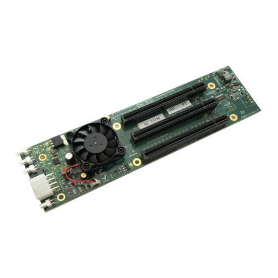
- Page 1 Expansion Backplane, 2 PCIe slots x8 3.0 (419) Model: OSS-BP-419 Installation Guide SKU: OSS-BP-419 www.onestopsystems.com...
-
Page 2: Table Of Contents
Connect Power Cord Power ON the system Verify Hardware Board Slot LEDs Target & Host Cards LEDs LED Definition Troubleshooting The OSS-419 board is not powering ON Both Target and Host cards are not linking up OSS- BP-419 | 2... - Page 3 One Stop Systems The Red LED on the board stays LIT all the time. My PCIe cards is not getting detected How to Get More Help 6.1 Contacting Technical Support 6.2 Returning Merchandise 6.3 Online Support Resources OSS- BP-419 | 3...
-
Page 4: Preface
Disclaimer: We have attempted to identify most situations that may pose a danger, warning, or caution condition in this manual. However, the company does not claim to have covered all situations that might require the use of a Caution, Warning, or Danger indicator. OSS- BP-419 | 4... -
Page 5: Safety Instructions
Also, before connecting a cable, make sure both connectors are correctly oriented and aligned. CAUTION Do not attempt to service the system yourself except as explained in this manual. Follow installation instructions closely. OSS- BP-419 | 5... - Page 6 Handle all sensitive components at an ESD workstation. If possible, use anti-static floor pads and workbench pads. Handle components and boards with care. Do not touch the components or contacts on a board. Hold a board by its edges or by its metal mounting bracket. OSS- BP-419 | 6...
-
Page 7: Introduction
Single 12V Input Option: Available Power 134W (11.16A) Slot (1) x16 PCIe Gen 3 Host Interface Slot One OSS PCIe x16 3.0 target slot for OSS target cable adapter (2) x8 PCIe Gen 3 Endpoint Slots Two PCIe x8 3.0 expansion slots (x16 mechanical) On-Board Regulated Voltages 0.9V, 1.8V, 3.3V/3.3VStandby... -
Page 8: Overview
PWR / Fault LED: Indicates error on the board, power not initialized. +12V AUX OUT : External AUX power for PCIe card requiring additional power. Fan Connectors: For connecting external fans 1.2.1 Connector Pinouts OSS- BP-419 | 8... -
Page 9: Block Diagram
One Stop Systems Block Diagram Dimensions OSS- BP-419 | 9... -
Page 10: X16 Target Slot Connector Pin Outs
PRSNT_X4# RSVD Connector PETp4 RSVD PETn4 PERp4 PERn4 PETp5 PETn5 PERp5 PERn5 PETp6 PETn6 PERp6 PERn6 PETp7 PETn7 PERp7 End of the PRSNT_X8# PERn7 Connector PETp8 RSVD PETn8 PERp8 PERn8 End of the PETp9 PETn9 Connector OSS- BP-419 | 10... -
Page 11: X16 End Point Slot Connector Pin Outs
End Point Slot Connector Pin Outs Pin # Name Pin # Name +12V +12V +12V +12V +12V SMCLK SMDAT REFCLK2+ REFCLK2- +3.3V +3.3V 3.3Vaux +3.3V Mechanical WAKE# PERST# RSVD REFCLK1+ PERp0 REFCLK1- PERn0 End of the PETp0 PRSNT_X1# PETn0 Connector OSS- BP-419 | 11... - Page 12 PETp4 PETn4 PERp5 PERn5 PETp5 PETn5 PERp6 PERn6 PETp6 PETn6 PERp7 PERn7 PETp7 End of the PRSNT_X8# PETn7 Connector PERp8 RSVD PERn8 PETp8 PETn8 PERp9 PERn9 PETp9 PETn9 PERp10 PERn10 End of the PETp10 PETn10 Connector OSS- BP-419 | 12...
- Page 13 One Stop Systems PERp11 PERn11 PETp11 PETn11 PERp12 PERn12 PETp12 PETn12 PERp13 PERn13 PETp13 PETn13 PERp14 PERn14 PETp14 PETn14 PERp15 PERn15 PETp15 PRSNT_X16# PETn15 RSVD NC = NOT CONNECTED OSS- BP-419 | 13...
-
Page 14: Hardware Requirements
This section describes the supported configuration and hardware requirements to use to ensure the product works properly Supported Configuration The block diagram below shows the supported / valid configuration. This illustrates the proper way to set up and how to use the OSS-BP-419 board correctly. -
Page 15: Unsupported / Invalid Configuration
One Stop Systems Unsupported / Invalid Configuration Connecting “Other Backplane” or similar to OSS-BP-419. Using an unknown target adapter card or other brand of adapter card (made by different vendor). Connecting to host computer via onboard / built-in Ipass cable port. - Page 16 One Stop Systems Connecting the OSS-419 board to an unknown adapter card and connecting to host computer via onboard Ipass cable port. Using an unknown host adapter card or another brand (made by different vendor). OSS- BP-419 | 16...
-
Page 17: Hardware To Use
One Stop Systems Hardware to Use This section provides the hardware parts needed for the OSS-419 to work. It is strictly recommended to follow and use the hardware requirements listed below in order for the OSS-BP-419 board to operate properly. -
Page 18: X8 Ipass Cable
Use x8 iPass cable for linking host card and target card together. Preferably use a 1 meter long cable. 2.3.4 Power Supply There are several options to power up your OSS-419 board. You can use an external power brick or standard ATX power supply. External Power Brick: Photo below is an example of an external power brick ... -
Page 19: Software Requirement
The 4 pin +12 volt cable is polarized so it can only be plugged into the 4 pin board connector correctly. The motherboard connectors and the OSS backplane have the same square and rounded arrangement so the power cable only fits in one way. -
Page 20: Installation Procedures
The following steps will guide you through the installation of your backplane. Connect Power Supply This section shows you how to connect an external power brick or a standard power supply to OSS-419 board. You can either use an external power brick or a standard ATX power supply. -
Page 21: Standard Atx Power Supply
Makes sure you have the correct target card. To help you identify the card, below is a photo of the OSS HIB25-x8 Target card. Once you have identified the correct card to use, plug the “Target card” into the Upstream slot on the OSS-419 board. See photo below for the right location of the Upstream slot. -
Page 22: Install Oss Host Card
One Stop Systems The photo below shows the “Target Card” installed in the Upstream slot. Install OSS Host card Power down the host computer first before installing the host card. Do not install the host card while the computer is ON. -
Page 23: Install Pcie Card
CAUTION: Please unplug the power cord from the power supply before installing your PCIe cards. Plug-in your 3rd party PCIe card in the expansion backplane. Use the two available downstream slots on OSS backplane. See photos below. Connect Ipass cable ... -
Page 24: Connect Power Cord
If you are using an external power brick, simply plug-in the power-cord to the brick. Upon connecting the power cord to the power supply, the OSS-419 board will be on a “stand-by power” mode and the RED LED on the board will illuminate as shown from the photo below. -
Page 25: Power On The System
Is the Host card is plugged into a Gen3 x8 or Gen3 x16 slot in the computer’s motherboard and is fully seated? Ensure that the two slots on the OSS-419 backplane are populated with your PCIe cards and are fully seated in the slot? Is the Power supply cable connected to the INPUT power connection on the OSS-419 board? ... -
Page 26: Verify Hardware
One Stop Systems Verify Hardware Verify all the LED indicators on the board and cards are properly illuminated. Board Slot LEDs On the OSS-419 backplane, the following LEDs are illuminated as solid green. SLT1: Slot 1 SLT2: Slot 2 ... -
Page 27: Troubleshooting
The Red LED on the board stays LIT all the time. This is likely a indication that your OSS-419 board is faulty or you may have a components failure on the board. Contact OSS Technical Support. You may need to send the board for repair, if it is under warranty Buy a replacement board If the board is not getting initialized, the RED FAULD LED will stay ON. - Page 28 If you need technical support, product assistance or have a technical inquiry we encourage you to submit it on-line using our Technical Support Form. If you need to send a unit for repair or diagnostic evaluation, fill out our RMA (Return Material Authorization) online request form. https://www.onestopsystems.com/support OSS- BP-419 | 28...
- Page 29 One Stop Systems OSS- BP-419 | 29...
Need help?
Do you have a question about the OSS-BP-419 and is the answer not in the manual?
Questions and answers