
Subscribe to Our Youtube Channel
Related Manuals for OSS OSS-521 Gen4


Summary of Contents for OSS OSS-521 Gen4
- Page 1 OSS-521 Gen4 Backplane INSTALLATION GUIDE OSS-521 Gen4 Backplane www.onestopsystems.com...
-
Page 2: Table Of Contents
Slot Type ..........................7 ARF6 Connectors ........................8 PS_ON ........................... 8 Block Diagram .......................... 9 Slot Configurations ........................10 3.10 OSS-521 Backplane with Kit vs. no Kit ..................... 12 3.11 Use Case Diagrams ........................13 3.12 Supported Setup ........................15 3.13 Not Supported Setup ......................... - Page 3 My PCIe devices are showing UP with a Yellow Exclamation mark ............. 36 13.3 No link between host and target cards .................... 36 13.4 Broken OSS-Backplane ....................... 36 13.5 My PCIe cards are not detected ....................36 How to Get More Help ..................... 37 14.1...
-
Page 4: Getting Started
Check and identify the standard supplied item. Inspect the backplane for physical defects and damages. To achieve good performance and reliability it is recommended to use a certified and compatible set of an OSS Gen4 adapter cards (aka: Host Interface Board) and a Gen4 Mini-SAS HD SFF-8644 cables. -
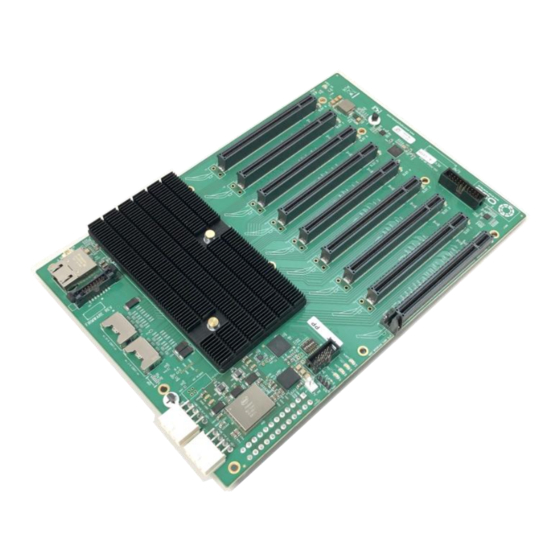
Page 5: Description Of Parts
For connecting ATX Power Supply PCIe Switch Port PCIe switch management port, optional ARF 6 Bottom Connectors For connecting ARC 6 cables between ”Option slot” and PEX switch Screw-Mounting Holes For securing the board on to an enclosure OSS-521 Gen4 BP... -
Page 6: Upstream And Downstream Slots
One Stop Systems Upstream and Downstream Slots Upstream Slot: Also known as target slot. Designated slot for the Target adapter card only. OSS Host card or any PCIe cards will not operate in the Upstream slot / Target slot. ... -
Page 7: Board Leds
Slot Type Slot Type: Closed-ended PCIe slot / connector, all the slots are x16 mechanical. Six x8 electrical slots (slots 1, 2, 3, 4, 5 and 6) Three x16 electrical slots(slots 0, 7 and 8) OSS-521 Gen4 BP... -
Page 8: Arf6 Connectors
The board has a two-pin connector for placing a shunt / jumper that allows the backplane to be ON all the time when an ATX power supply is switched ON. See photos below for the location of the JP5 connector on the backplane. OSS-521 Gen4 BP... -
Page 9: Block Diagram
One Stop Systems Block Diagram OSS-521 Gen4 BP... -
Page 10: Slot Configurations
Without those ARC6 cables nothing will work in SLOT 8. Configuration# 2: Two Upstream slots (Slot 0 and SLOT 8) with two partitions. Slot 0: Partition #1 with four Downstream slots Slot 8: Partition #2 with three Downstream slots OSS-521 Gen4 BP... - Page 11 One Stop Systems Configuration# 3: Two backplanes are daisy chained together. One Upstream slot and 15 Downstream slots. OSS-521 Gen4 BP...
-
Page 12: Oss-521 Backplane With Kit Vs. No Kit
3.10 OSS-521 Backplane with Kit vs. no Kit OSS-521 backplane with kit, which includes two ARC 6 cables installed to enable slot 8, see photos below. Part# OSS-BP-521-LSKIT OSS-521 backplane with no kit installed (no ARC 6 cables), see photos below. -
Page 13: Use Case Diagrams
One Stop Systems 3.11 Use Case Diagrams Configuration 1 OSS-521 backplane is linked to a single host computer. Four x4 link cables are connected between OSS Gen4 Host card and Target card. 8 Downstream slots 6 x8 slots (Slot 1, 2, 3, 4, 5 and 6) ... - Page 14 One Stop Systems Configuration 3 Two OSS-521 backplane are daisy chained together and it is linked to a single host computer. With a total of 15 Downstream slots 1st backplane: 7 downstream slots 6 x8 slots (slot 1, 2, 3, 4, 5 and 6) ...
-
Page 15: Supported Setup
One Stop Systems 3.12 Supported Setup This is a validated /supported setup for using the OSS-521 backplane with a host computer and an OSS HIB adapter cards. Requires a set of OSS-PCIe-HIB616-x16 card, configured as Target and Host cards. -
Page 16: Slot Number And Port Mapping
3.14 Slot Number and Port Mapping Each slot on the OSS backplane is mapped to a PCIe port on the 88096 PCIe switch. Port mapping is hard-coded, it is essentially fixed. No means of changing or modifying it. For example, a single GPU or PCIe card is seated in slot 2 on the backplane, PCIe port 56 will be automatically assigned to the card. -
Page 17: Hardware Requirements
Use Gen 4 PCI Express (PCIe) rated cables. This passive copper cable mates to the SFF-8644 connectors on the HIB6xx family of OSS host interface board. Tested and validate with 1m, 2m and 3m lengths. Single or multiple cables can form larger PCIe links. -
Page 18: Backplane Installation
Turn the backplane over to access the onboard 24-PIN ATX Power connector. Connect the ATX power cable to the onboard 24-PIN ATX power connector as shown from the photos below. Connect the 12v Aux power cables to the 12V input connectors. OSS-521 Gen4 BP... - Page 19 OSS-521backplane. 4UP enclosure: Applicable for “dual backplane” installation EB4400 enclosure: For “single backplane” installation Place the OSS-backplane on top of the stand-offs and align the screw-mounting holes. Secure the backplane with the screws. OSS-521 Gen4 BP...
-
Page 20: Cable Adapter Card Installation
One Stop Systems Cable Adapter Card Installation To operate the backplane you need two OSS compatible / certified “HIB adapter cards". Use an OSS Gen4 x16 PCIe Host *& Target cable adapter cards. Target card: HIB card configured to operate in target mode. This is an OSS certified and compatible HIB card installed directly on the OSS backplane’s target slot / upstream slot. -
Page 21: Host Card Installation
Host Card Switch Settings (x16 Configuration) SW1 #2 = ON; #5 =ON. SW2 #1 = ON; #2 = ON Note: For more information on different host card dipswitch settings / configurations please check the OSS-PCIe-HIB616-x16 installation guide. OSS-521 Gen4 BP... - Page 22 Align the host card PCIe connector on top of the PCIe slot. Carefully push the card down until it is firmly seated and secure it. The photos below are example of x16 PCIe slot. For easy identification on the PCIe slot specification check the label or silk-screen next to the connector. OSS-521 Gen4 BP...
-
Page 23: Cable Installation
Port#2 on both Target and Host cards Plug-in the 4 cable to Port#3 (Bottom port) on both Target and Host cards For more details on different cable configurations please refer to the OSS-PCIe-HIB616-x16 installation guide. https://www.onestopsystems.com/product/pcie-x16-gen-4-cable-adapter OSS-521 Gen4 BP... -
Page 24: Pcie Card Installation
OSS-521 backplane configured with two Upstream slots (SLOT 0 and SLOT 8). Use Slots# 1, 2, 3, 4, 5, 6 and 7 for your endpoint device. The slot 0 and 8 will operate in an Upstream mode and will only work with an OSS HIB card configured as target. -
Page 25: Hardware Check
After powering UP the host computer, the Target SLOT LED on the backplane will lit as solid green. A fully operational back plane will illuminate the following LEDs. D19- Blinking green (LED 1). D18-Solid green(LED 0). D16- AUX power, solid green. OSS-521 Gen4 BP... -
Page 26: Fault Leds (Red)
One Stop Systems 10.2 Fault LEDs (RED) A solid RED led on the backplane signifies a fault or an error. Below photos are list of RED LED locations and definitions. OSS-521 Gen4 BP... -
Page 27: Verify Adapter Card Leds
CHO LED will illuminate as solid green, indicates of a stable LINK between Target and Host cards. When there is no link between Target and Host cards, the CHO LED is OFF. The C9-Aux power LED will illuminate as solid green, an indication of power is present on the card. OSS-521 Gen4 BP... -
Page 28: Slot Leds
The SLOT LEDs will illuminate either solid green or blinking green depending on the Generation of the PCIe card that is occupying the slot. The Target SLOT LED will illuminate as solid green (Gen 4). Solid Gen4 Link Blink 2Hz Gen3 Link Blink 1Hz Gen2 Link Blink 0.5Hz Gen1 Link (Slow Blinking) No card installed OSS-521 Gen4 BP... -
Page 29: Verify Oss Devices
11.1 Linux OS To check if the OSS HIB cards and backplane are detected, use the following commands on the terminal window. You must logged-in as “super user (or as root)” when running the lspci command. #lspci –tv | grep c010. - Page 30 #lspci –vvv | grep c010. The output below shows that the operating system is recognizing the OSS Host card, Target card and backplane. The output below shows that the operating system is only detecting the Host card. No link between Target card and Host card.
-
Page 31: Windows 10 / Server
Photo below shows the backplane, target card and host card are detected. OSS backplane with PCIe cards installed—the downstream slots on the backplane are not populated. Showing multiple layers of PCI Express standard Upstream Switch Port and PCI Express standard Downstream Switch Port. OSS-521 Gen4 BP... - Page 32 One Stop Systems Viewing devices by type Both adapter cards (host and target cards) and backplane are recognized / detected. The devices are coming up with a Yellow Exclamation point, this is normal. No need to install any drivers. OSS-521 Gen4 BP...
-
Page 33: Verify Pcie Cards
lspci –vtt” command. Output below is a screenshot of the “lspci –vtt” showing the OSS backplane with seven cards that are detected. You can also grep the vendor name of the PCIe card. For example, if you have an NVIDIA GPUs, run the command on the terminal window “... -
Page 34: Windows
Switch Port and you will find all the PCIe devices that are detected. The screenshot below shows the OSS backplane is populated with five PCIe cards (but showing a yellow exclamation mark next to it, which means the driver is not loaded). You can obtain the driver from the card manufacturer or you can download it from the vendor’s website. - Page 35 One Stop Systems The screenshot below shows an Ethernet card is detected and it installed in slot#1. OSS-521 Gen4 BP...
-
Page 36: Troubleshooting
13.4 Broken OSS-Backplane If you received a brand new DOA (Dead on Arrival) board, please contact OSS to RMA board and request for a replacement. If you have an out of warranty board, please contact OSS Sales team and buy a new replacement board. -
Page 37: How To Get More Help
We test, certify and support many third party hardware and software products along with OSS hardware and are happy to integrate a fully supported system. Ask us about that service and we would be happy to help. If an OSS product is fully functional and a support issue is related to third-party hardware or software that did not ship from the OSS factory, the customer requesting support should reach out to the third-party vendor for assistance to fully troubleshoot the issue. - Page 38 One Stop Systems OSS-521 Gen4 BP...
Need help?
Do you have a question about the OSS-521 Gen4 and is the answer not in the manual?
Questions and answers