
Related Manuals for OSS OSS-KIT-EXP-3500-2M


Summary of Contents for OSS OSS-KIT-EXP-3500-2M
- Page 1 OSS-KIT-EXP-3500-2M PCIe x4 Gen 2 Expansion Kit User Manual SKU: OSS-KIT-EXP-3500-2M www.onestopsystems.com...
-
Page 2: Table Of Contents
Force Power ON ...................................... 10 Technical Information ..............................11 Signal Adjustment ....................................11 Pin Assignments ...................................... 11 PCI Express x4 Connector PIN Assignment .............................. 14 Contacting Technical Support ............................19 Technical Information Returning Merchandise to One Stop Systems ................19 OSS-KIT-EXP-3500-2M | 2... -
Page 3: Overview
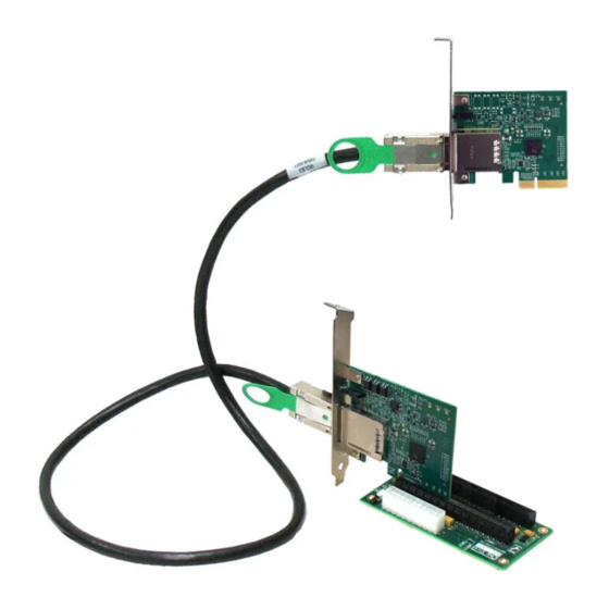
The PCIe x4 Gen 2 expansion kit is used to extend the PCI Express bus from a host server to an external PCIe I/O board. The host adapter card inserts into a PCIe slot of the server. It then cables to a downstream target adapter card. The target adapter card inserts in the OSS Gen 2, 2-slot backplane. -
Page 4: Features
The Host adapter card inserts into any PCI Express x4, x8, 16 slot on the host motherboard. The Target adapter card operates ONLY in the OSS backplane target slot. Both Host and Target adapter cards have PWR and CBL LED indicators. -
Page 5: Specifications
3.3@1.3A Agency Compliance FCC Class B, CE, ROHS Temperature Range 0° to 50°C (32° to 122°F) 1 PCIe x16 Gen 3 Target Slot backplane 412 (SKU : OSS-BP-412 ) Dimension (H x L) 2.25” x 4.5” Power ATX Power Supply 1 OSS target slot (Upstream Port) for target cable adapter only. -
Page 6: Component Identification
The PCIe x4 expansion kit contains two cable adapter boards, the host cable adapter and the target cable adapter. The host adapter inserts into the host computer’s PCIe x4, x8 or x16 slot. The host cable adapter (Part # OSS-PCIe-HIB25-x4-H) allows communication between a processor and an I/O point. -
Page 7: 2-Slot Backplane
Connector Pin-Outs Connector Definition Force Power ON Input Power (20 pin) Target Slot (Upstream Port) Endpoint Slot (Downstream Port Power Good LED Definition PWR_ON# P3: ATX 20 Pin Power Connector +3.3V +3.3V PWRON +5VSB +12V1 +3.3V -12V PS_ON# OSS-KIT-EXP-3500-2M | 7... -
Page 8: Dimensional Drawing
One Stop Systems 2.4.2 Dimensional Drawing OSS-KIT-EXP-3500-2M | 8... -
Page 9: Installation Instructions
Connect the x4 PCIe cable to both cables adapter cards. Press or pull the green TAB while slowly inserting the cable, then release it to lock the cable. See photos below. 3.3 Removing PCIe cable To remove the cable, press or pull the green tab and slowly pull the cable out. OSS-KIT-EXP-3500-2M | 9... -
Page 10: Operation
To remove the cable, press down the green tab and slowly pull the cable out. Or pull the green tab and slowly pull out the cable. 3.7 Force Power ON Install shunt or jumper on J2 connector to force power on the backplane. This is not required for normal operation. OSS-KIT-EXP-3500-2M | 10... -
Page 11: Technical Information
In the following tables, a 0 indicates that a zero Ohm resistor has been installed and a 1 indicates no resistor. In rare cases, mostly where non- OSS equipment is used with the HIB-25x4, these adjustments may need to be changed. The following tables are made available for this purpose. - Page 12 Ground Ground PERp2 Receiver differential pair, Lane 2 Ground PERn2 PETp3 Transmitter differential pair, Ground Lane 3 PETn3 Ground Ground PERp3 Receiver differential pair, Lane 3 RSVD Reserved PERn3 PRSNT2# Hot-Plug presence detect Ground Ground RSVD Reserved OSS-KIT-EXP-3500-2M | 12...
- Page 13 Although support of CWAKE# is optional from the board side connector perspective, an allocated wire is mandated for the cable assembly. Board side pin-outs on both sides of the Link are identical. The cable assembly incorporates a null modem for the PCIe transmit and receive pairs. OSS-KIT-EXP-3500-2M | 13...
-
Page 14: Pci Express X4 Connector Pin Assignment
PERn1 PETn1 PERp2 Differential Pair PETp2 PERn2 PETn2 PERp3 Differential Pair PETp3 PERn3 PETn3 PWR_RTN PWR_RTN PWR_RTN PWR_RTN CWAKE# Hook-up Wire CWAKE# CPERST# Hook-up Wire CPERST# Overall Cable Back shell Chassis Ground Chassis Ground Back shell Braid OSS-KIT-EXP-3500-2M | 14... - Page 15 End of the x1 Connector PETp1 RSVD PETn1 PERp1 PERn1 PETp2 PETn2 PERp2 PERn2 PETp3 PETn3 PERp3 RSVD PERn3 PRSNT_X4# End of the x4 RSVD Connector PETp4 RSVD PETn4 PERp4 PERn4 PETp5 End of the x8 PETn5 Connector OSS-KIT-EXP-3500-2M | 15...
- Page 16 PERp8 PERn8 PETp9 PETn9 PERp9 PERn9 PETp10 PETn10 PERp10 PERn10 PETp11 PETn11 PERp11 PERn11 PETp12 PETn12 PERp12 PERn12 PETp13 PETn13 PERp13 PERn13 PETp14 PETn14 PERp14 PERn14 PETp15 PETn15 PERp15 PRSNT_X16# PERn15 End of the x16 RSVD Connector OSS-KIT-EXP-3500-2M | 16...
- Page 17 PERp4 RSVD PERn4 PETp4 PETn4 PERp5 PERn5 PETp5 PETn5 PERp6 PERn6 PETp6 PETn6 PERp7 PERn7 PETp7 PRSNT_X8# PETn7 End of the x8 Connector PERp8 RSVD PERn8 PETp8 PETn8 PERp9 PERn9 PETp9 End of the x16 PETn9 Connector OSS-KIT-EXP-3500-2M | 17...
- Page 18 One Stop Systems PERp10 PERn10 PETp10 PETn10 PERp11 PERn11 PETp11 PETn11 PERp12 PERn12 PETp12 PETn12 PERp13 PERn13 PETp13 PETn13 PERp14 PERn14 PETp14 PETn14 PERp15 PERn15 PETp15 PRSNT_X16# PETn15 RSVD OSS-KIT-EXP-3500-2M | 18...
-
Page 19: Contacting Technical Support
6 Technical Information Returning Merchandise to One Stop Systems If factory service is required, you must contact OSS Service Representative to obtain a Return Merchandise Authorization (RMA) number. Put this number and your return address on the shipping label when you return the item(s) for service. One Stop Systems will return any product that is not accompanied by an RMA number. - Page 20 One Stop Systems OSS-KIT-EXP-3500-2M | 20...
Need help?
Do you have a question about the OSS-KIT-EXP-3500-2M and is the answer not in the manual?
Questions and answers