
Subscribe to Our Youtube Channel
Related Manuals for OSS OSS-PCIe-HIB38-x8-QUAD


Summary of Contents for OSS OSS-PCIe-HIB38-x8-QUAD
- Page 1 PCIe x8 Gen3 Host Cable Adapter with PCIe Switch Model: OSS-PCIe-HIB38-x8-QUAD Installation Guide SKU: OSS-PCIe-HIB38-X8-QUAD www.onestopsystems.com...
-
Page 2: Table Of Contents
One Stop Systems Table of Contents Preface Advisories Safety Instructions Introduction Specifications Features: Overview 1.3.1 OSS-386 Main board 1.3.2 OSS-390 Mezzanine Board PCIe Card Edge Power PCIe Cable Sideband signals PLX PEX8749 Link LEDS Board LEDs 1.9.1 OSS-386 board LEDs 1.9.1... - Page 3 Connect ATX Power Supply Power ON the system Verify Hardware Target card LEDs Host card LEDs 4.2.1 OSS-390 Board LEDs 4.2.2 OSS-386 Board LEDs Bracket Link LED Indicators Verify Device in Windows OS Software Installation How to Get More Help 7.1 Contacting Technical Support...
-
Page 4: Preface
Disclaimer: We have attempted to identify most situations that may pose a danger, warning, or caution condition in this manual. However, the company does not claim to have covered all situations that might require the use of a Caution, Warning, or Danger indicator. OSS-PCIe-HIB38x8-QUAD | 4... -
Page 5: Safety Instructions
Also, before connecting a cable, make sure both connectors are correctly oriented and aligned. CAUTION Do not attempt to service the system yourself except as explained in this manual. Follow installation instructions closely. OSS-PCIe-HIB38x8-QUAD | 5... - Page 6 Handle all sensitive components at an ESD workstation. If possible, use anti-static floor pads and workbench pads. Handle components and boards with care. Do not touch the components or contacts on a board. Hold a board by its edges or by its metal mounting bracket. OSS-PCIe-HIB38x8-QUAD | 6...
-
Page 7: Introduction
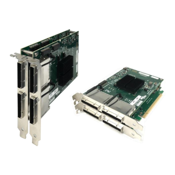
Introduction The PCIe x8 Gen 3 cable adapter with PCIe switch is a PCIe half-height add-in card with two boards (OSS-386 and OSS-390) attached together with four x8 cable external connectors on the slot cover. It operates in upstream mode with Dipswitch setting change. The host cable adapter installs in the PCIe slot of a computer’s motherboard only. -
Page 8: Features
iPass x8 external cable connector Overview This is an overview on HIB38-x8-QUAD card. The quad card is composed of two boards, the mezzanine / daughter card (OSS-390) and the HIB card (OSS-386). The OSS-390 is mounted on top of the OSS-386 board. -
Page 9: Oss-386 Main Board
One Stop Systems 1.3.1 OSS-386 Main board The OSS-386 board has the following: Card Edge Connector 6 Dipswitches (SW1) Male mezzanine connector on the front-side of the board Two x8 external cable connector PLX 8749... -
Page 10: Oss-390 Mezzanine Board
One Stop Systems 1.3.2 OSS-390 Mezzanine Board The OSS-390 mezzanine board has the following: 4 Dipswitches (SW1) Female mezzanine connector on the back-side of the board Two x8 external cable connector PLX 8733 OSS-390 does not have the card-edge connector... -
Page 11: Pcie Card Edge
Power is provided by the PCI-e card slot. Power required by internal components of OSS-PCIe-HIB-38-x8 -QUAD is estimated to be 20 watts when all ports are fully linked and operating in Gen3 mode. Cable power is to be provided per PCIe cable specification. When an active cable (powered transceiver) is used, additional power is required from the PCI-e card slot. -
Page 12: Board Leds
One Stop Systems Board LEDs There are two LEDs on the OSS-386 and OSS-390 boards. They are located in the upper right of the board. PWRGD--Power good, board has power CE LINK—Card edge, successful link with the card edge 1.9.1... -
Page 13: 1.10 Block Diagram
One Stop Systems 1.10 Block Diagram OSS-PCIe-HIB38x8-QUAD | 13... -
Page 14: Dimensions
One Stop Systems 1.11 Dimensions OSS-PCIe-HIB38x8-QUAD | 14... -
Page 15: Operating Mode
There are 4 dipswitches on the OSS-390 Mezzanine board. Host mode settings, #1=ON ; #2=OFF ; #3=OFF ; #4=OFF. OSS-386 Board There are 6 dipswitches on the OSS-386 main board. Host mode settings, #1=ON ; #2=OFF ; #3=OFF ; #4=OFF ; #5=OFF and #6 =ON. 1.12.2 Target Mode A separate HIB38-X8-Dual card (OSS-386 board) card is required to use as target. -
Page 16: Card Edge Connector Pin Outs
Transmitter differential pair, Lane 6 Ground Ground PERp6 Ground PERn6 Receiver differential pair, Lane 6 PETp7 Ground PETn7 Transmitter differential pair, Lane 7 Ground Ground PERp7 PRSNT2# Hot-Plug presence detect PERn7 Receiver differential pair, Lane 7 Ground Ground OSS-PCIe-HIB38x8-QUAD | 16... -
Page 17: X8 Cable Wire Connections / Pin Outs
CREFCLK- PWR (3.3V) PWR (3.3V) RSVD PWR RTN RSVD PWR RTN SB_RTN PWR RTN CPSRNT$# CWAKE# CPWRON CPERST# PETp4 PETp4 PETn4 PERp4 PETp5 PERp5 PETn5 PERn5 PETp6 PERp6 PETn6 PERn6 PETp7 PERp7 PETn7 PERn7 *NC: Not Connected OSS-PCIe-HIB38x8-QUAD | 17... -
Page 18: X8 Cable Signal Descriptions
Power: Provides local power for in-cable redriver circuits. Only needed on long cables (Power does not go across the cable.) PWR_RTN Po Provides local power return path for PWR pins. CWAKE# Cable WAKE CPERST# Cable PCI Express Reset OSS-PCIe-HIB38x8-QUAD | 18... -
Page 19: Mezzanine Connector Pin Outs
Receiver differential pair, Lane 14 PERp1 Receiver differential pair, Lane 1 PETp14 Receiver differential pair, Lane 14 PERn0 Receiver differential pair, Lane 0 PETn15 Receiver differential pair, Lane 15 PERp0 Receiver differential pair, Lane 0 PETp15 Receiver differential pair, Lane 15 OSS-PCIe-HIB38x8-QUAD | 19... -
Page 20: Hardware Requirements
One x8 iPass cable or four x8 iPass cables (depending if you are connecting 4 expansion units). A maximum of four expansion units can be connected to the HIB38-x8-QUAD host card. OSS Expansion chassis with Gen3 backplane, or OSS expansion backplane and power supply. 2.1.1 HIB38-x8-QUAD card (Host) HIB38-x8-QUAD card: OSS-386 and OSS-390 boards are attached together. -
Page 21: Pcie Slot & Motherboard Requirement
Expansion Chassis / backplanes You need an expansion chassis with Gen3 or Gen3 backplane . Photos below are example of an OSS backplanes and an expansion unit. OSS offers a multitude of expansion units and expansion backplanes, please visit our website to get further details on all products. Here is the web link: https://www.onestopsystems.com... -
Page 22: Atx Power Supply
One Stop Systems 2.1.5 ATX Power Supply If you are using an OSS backplane with the HIB38-x8-DUAL card, you need a power supply unit to provide power. A standard ATX power supply will work with the boards. Software Requirement Computer running Windows 7, 8, 10 and or Server... -
Page 23: Installation Procedures
OSS-386 card: set the dipswitches to #1=ON ; #2=OFF; #3=OFF; #4=OFF; #5=OFF; #6=ON OSS-390 card: set the dipswitches to #1=ON; #2=OFF; #3=OFF, #4=OFF Set the dipswitches on the target card, using a separate OSS-386 card (HIB38-x8-DUAL) , see photos below. OSS-PCIe-HIB38x8-QUAD | 23... -
Page 24: Install Host Card
Install Target card Install the Target card in the OSS expansion backplane. Plug-in the target card in the “Upstream” slot. Do not plug in the target card while expansion unit or the expansion backplane is ON as this can damage the board. Turn OFF the unit first before installing the card. -
Page 25: Install Pcie Card
Photos below are some of the different backplanes showing where the locations of the “Upstream” slot. Install PCIe card Plug-in your third party PCIe card in the expansion backplane. Use the downstream slot on the OSS backplane. See photos below for the location of the downstream slot / end-point slot. -
Page 26: Install X8 Ipass Cable
Plug in the cable to the Target card. Connect the cable to the “top external connector / port”. Do not use the bottom port of the card. Make sure the cable is firmly latched in to the cable connectors of the card. If you are connecting 4 expansion units, use one cable per expansion unit. See photos below. OSS-PCIe-HIB38x8-QUAD | 26... -
Page 27: Connect Cable To Host Card
Connect Cable to Host card Plug in the other end of the four cables to the Host card. If you are only connecting a single cable, you can either use the top or bottom port of the host card. OSS-PCIe-HIB38x8-QUAD | 27... -
Page 28: 3.5.3 Use Case Diagrams
One Stop Systems 3.5.3 Use Case Diagrams Four expansion units FIG: A1 Three expansion units FIG: B1 FIG: B2 OSS-PCIe-HIB38x8-QUAD | 28... -
Page 29: Connect Atx Power Supply
If you are using an expansion chassis, the power supply is already part of the unit. You can skip this step. If you are using an expansion backplane, plug-in the ATX power supply cable into the 24pin ATX power connector on the OSS board. -
Page 30: Power On The System
If the expansion unit or the HIB card are not powering ON, check the link cable make sure it is firmly connected. The target and host card must be fully seated in the PCIe slot in order to work correctly. OSS-PCIe-HIB38x8-QUAD | 30... -
Page 31: Verify Hardware
Bracket LED : Solid green – Gen 3 or Blinking green – Gen 2 (Blinking frequency: 2Hz ). Gen1 (Blinking frequency: 1Hz) Board LEDs : PWRGD – Solid green CE LINKED – Solid green or blinking green, depending on the blink rate. Gen3- solid green Gen2 - Blinking frequency: 2Hz Gen1 - Blinking frequency: 1Hz OSS-PCIe-HIB38x8-QUAD | 31... -
Page 32: Oss-390 Board Leds
One Stop Systems 4.2.1 OSS-390 Board LEDs D1 = green, power good indicator CR3 = green, port is good 4.2.2 OSS-386 Board LEDs D1 (PWRDG) = green, power good indicator CR3 (CE LINKED) = green, card edge link indicator... -
Page 33: Bracket Link Led Indicators
One Stop Systems Bracket Link LED Indicators Green – Successful link between host and target Red – Fatal error on PCIe switch. Faulty. No LED – No power. No link. Faulty port. OSS-PCIe-HIB38x8-QUAD | 33... -
Page 34: Verify Device In Windows Os
In Windows 7, Windows 10 or Windows Server Device Manager, you should see 8 instances of “Base System Device” coming up with a “Blue Question mark” or Yellow exclamation mark. It is normal for the OSS device to show up with the yellow bang, no need to install the driver, the device will operate properly. - Page 35 One Stop Systems On a standard workstation / desktop computer, if you go to Device Manager and view it “devices by connection”, the OSS-386 and 0SS-390 will be enumerated / recognized as “PCI standard PCI-to-PCI bridge”, see photos below. The first PCI standard PCI-to-PCI bridge is the OSS-386 board per PLX 8749.
- Page 36 One Stop Systems On a server platform running Server OS, the OSS boards will appear below the “PCI Express standard Root Port” and come up as “PCI Express standard Upstream Switch Port” and “PCI Express standard Downstream Switch Port”, see screenshot below.
-
Page 37: Software Installation
One Stop Systems Software Installation No software or driver is required for the Host Adapter card. OSS-PCIe-HIB38x8-QUAD | 37... -
Page 38: How To Get More Help
If you need technical support, product assistance or have a technical inquiry we encourage you to submit it on-line using our Technical Support Form. If you need to send a unit for repair or diagnostic evaluation, fill out our RMA (Return Material Authorization) online request form. https://www.onestopsystems.com/support OSS-PCIe-HIB38x8-QUAD | 38... - Page 39 One Stop Systems OSS-PCIe-HIB38x8-QUAD | 39...
Need help?
Do you have a question about the OSS-PCIe-HIB38-x8-QUAD and is the answer not in the manual?
Questions and answers