
Related Manuals for OSS OSS-PCIe4-BP-5X16


Summary of Contents for OSS OSS-PCIe4-BP-5X16
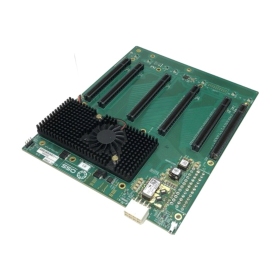
- Page 1 OSS-PCIe4-BP-5X16 Gen 4 Expansion Backplane, 5 PCIe x16 slots (522) INSTALLATION GUIDE SKU: OSS-BP-522 www.onestopsystems.com...
-
Page 2: Table Of Contents
Board LEDs ........................................ 6 Slot Type ........................................7 Force Power ON ......................................7 Block Diagram ......................................7 3.6. Host and OSS backplane ..................................8 Supported Setup ....................................... 8 Not Supported Setup ....................................8 Hardware Requirements ............................10 OSS-PCIe-HIB616-x16 card ..................................10 SFF-8644 Gen4 x4 Cable .................................. - Page 3 One Stop Systems 10.1 Returning Merchandise to One Stop Systems ........................... 29 OSS-PCIe4-BP-5X16...
-
Page 4: Getting Started
Link Cable Installation Powering Up the unit / system Board LED Indicator Verify Device Installation Unpacking Check and identify the standard supplied item. Inspect the backplane to make sure it is free from physical defects and damages. OSS-PCIe4-BP-5X16... -
Page 5: Description Of Parts
12V input power for the 522 board. Not to be used for external GPU aux. PCIe Switch & Fan PLX PCIe Switch and Heat sink / Fan 24-pin ATX Power Connector Use for ATX Power Supply to provide power to the board Screw-Mounting Holes For securing the board OSS-PCIe4-BP-5X16... -
Page 6: Board Leds
Aux Power LED Auxiliary Board power LED This is GREEN, denotes existence of auxiliary Board is at fault / error power +5VAUX LED Name Target LED SLOT 1 SLOT 2 SLOT 3 Reset Slot 4 Slot 5 LED Component PCIe Connector OSS-PCIe4-BP-5X16... -
Page 7: Slot Type
Force Power ON The board has a connector for a shunt / jumper, which allows the backplane to force the ATX supply to power on. See photos below for the location of the J1 connector on the backplane. Block Diagram OSS-PCIe4-BP-5X16... -
Page 8: Host And Oss Backplane
Host and OSS backplane Supported Setup This is a validated /supported setup for using the backplane with a host computer and HIB adapter cards. Using a set of OSS-PCIe-HIB616-x16 card (Target and Host cards), OSS Gen4 backplane ... - Page 9 Third Party HIB Cable Adapter cards Using a non OSS HIB cable adapter cards with the backplane is not supported. Customer is solely responsible for troubleshooting their non OSS HIB cable adapter cards when problem arises upon using it with the 2 backplane. ...
-
Page 10: Hardware Requirements
A pair of HIB616-x16 cards, one as host card and the other as target card SFF-8644 Gen4 x4 Cable Use Gen 4 PCI Express (PCIe) rated cables. This passive copper cable mates to the SFF-8644 connectors on the HIB6xx family of OSS host interface board. -
Page 11: Expansion Chassis / Gen4 Backplane
One Stop Systems Expansion Chassis / Gen4 Backplane OSS-PCIe4-BP-5X16... -
Page 12: Backplane Installation
Turn the backplane over to access the onboard 24-PIN ATX Power Connector. Connect the ATX power cable to the onboard 24-PIN ATX Power Connector as shown from the photos below. Install the board in the chassis / enclosure. The photos below are two available enclosures for the OSS-522 backplane. OSS-PCIe4-BP-5X16... - Page 13 One Stop Systems Place the OSS-522 backplane on top of the stand-offs and align the screw-mounting holes. Secure the backplane with the screws. OSS-PCIe4-BP-5X16...
-
Page 14: Cable Adapter Card Installation
Target card: Installed directly on the OSS backplane’s target slot Host Card: Installed in the host computer motherboard’s PCIe slot. For more details on OSS-PCIe-HIB616-x16 card (Host / Target card) please refer to the OSS-PCIe-HIB616-x16installation guide. https://www.onestopsystems.com/product/pcie-x16-gen-4-cable-adapter Target Card Installation Use the designated Target Slot / Upstream Slot when installing the card. -
Page 15: Host Card Installation
Host Card Dipswitch Settings (x16 Configuration) SW1 #2 = ON; #5 =ON. SW2 #1 = ON; #2 = ON Note: For more information on different host card dipswitch settings / configurations please check the OSS-PCIe-HIB616-x16 installation guide. OSS-PCIe4-BP-5X16... - Page 16 Align the host card PCIe connector on top of the PCIe slot. Carefully push the card down until it is firmly seated and secure it. The photos below are example of x16 PCIe slot. You can easily identify the specification of the PCIe slot by reading the silk-screen next to it. OSS-PCIe4-BP-5X16...
-
Page 17: Cable Installation
One Stop Systems Cable Installation Connecting the Link Cables x16 configuration: FOUR cables Note: Make sure the HIB616-x16 host card is set to x16 configuration, see x16 switch settings. Refer to the OSS-PCIe-HIB616-x16installation guide. Plug-in the 1 cable to Port#0 (Top port) on both Target and Host cards ... -
Page 18: Powering Up The Unit
After the host computer is powered UP, the Target LED on the backplane will come up as solid green. Target SLOT LINK LED Slot LINK LEDs and AUX LED The SLOT Link LED will come ON if a PCIe card is occupying the slot. The AUX LED will be lit as solid green OSS-PCIe4-BP-5X16... -
Page 19: Verify Device Installation
On Linux operating system, to verify or check if the board is detected or not, type the command below on the terminal window. $lspci –vvv | grep c012, see output below: $lspci –tvvv | grep LSI, see output below $lspci –m | grep 00b2, see output below. OSS-PCIe4-BP-5X16... - Page 20 One Stop Systems $lspci –vvvvt, this will give you the entire devices in a tree format. Output below is a cropped screenshot of the lspci –tvvv showing the OSS-522 backplane with no PCIe cards installed. OSS-PCIe4-BP-5X16...
- Page 21 Output below is a cropped screenshot of the “lspci –tvvv” showing the OSS-522 backplane with five cards installed. Output below is a cropped screenshot of the “lspci –tvvv” showing the OSS-522 backplane with a single card installed in SLOT# 5 Output below is a cropped screenshot of the “lspci –tvvv”...
- Page 22 One Stop Systems Output below is a cropped screenshot of the “lspci –tvvv” showing the OSS-522 backplane with a single card installed in SLOT# 2. Output below is a cropped screenshot of the “lspci –tvvv” showing the OSS-522 backplane with a single card installed in SLOT# 3.
-
Page 23: Windows
Collapse or click the ‘+’ or ‘>’ sign next to PCI standard PCI-to-PCI bridge and you will find all the PCIe devices that are detected. The screenshot below shows five PCIe devices that are detected but showing a yellow exclamation mark next to it, which means the driver is not loaded. OSS-PCIe4-BP-5X16... - Page 24 One Stop Systems The screenshot below shows NO PCIe cards are installed on the OSS-522 backplane. OSS-PCIe4-BP-5X16...
- Page 25 One Stop Systems The screenshot below shows the 5 PCIe slots on OSS-522 backplane. Below screenshot is showing the OSS-522 backplane with a single PCIe card installed in SLOT# 1 OSS-PCIe4-BP-5X16...
- Page 26 One Stop Systems Below screenshot is showing the OSS-522 backplane with a single PCIe card installed in SLOT# 2 Below screenshot is showing the OSS-522 backplane with a single PCIe card installed in SLOT# 3 OSS-PCIe4-BP-5X16...
- Page 27 One Stop Systems Below screenshot is showing the OSS-522 backplane with a single PCIe card installed in SLOT# 4 Below screenshot is showing the OSS-522 backplane with a single PCIe card installed in SLOT# 5 OSS-PCIe4-BP-5X16...
-
Page 28: Troubleshooting
Broken OSS-522 board If you received a brand new DOA (Dead on Arrival) board, please contact OSS to RMA board and request for a replacement. If you have an out of warranty board, please contact OSS Sales team and buy a new replacement board. -
Page 29: Contacting Technical Support
10.1 Returning Merchandise to One Stop Systems If factory service is required, you must contact OSS Service Representative to obtain a Return Merchandise Authorization (RMA) number. Put this number and your return address on the shipping label when you return the item(s) for service. One Stop Systems will return any product that is not accompanied by an RMA number. - Page 30 One Stop Systems OSS-PCIe4-BP-5X16...
Need help?
Do you have a question about the OSS-PCIe4-BP-5X16 and is the answer not in the manual?
Questions and answers